mit41301
SIM800L and SIM800H:
In the SIM800 family, SIM800L and SIM800H is having FM radio function. In addition SIM800H module also having Bluetooth function.


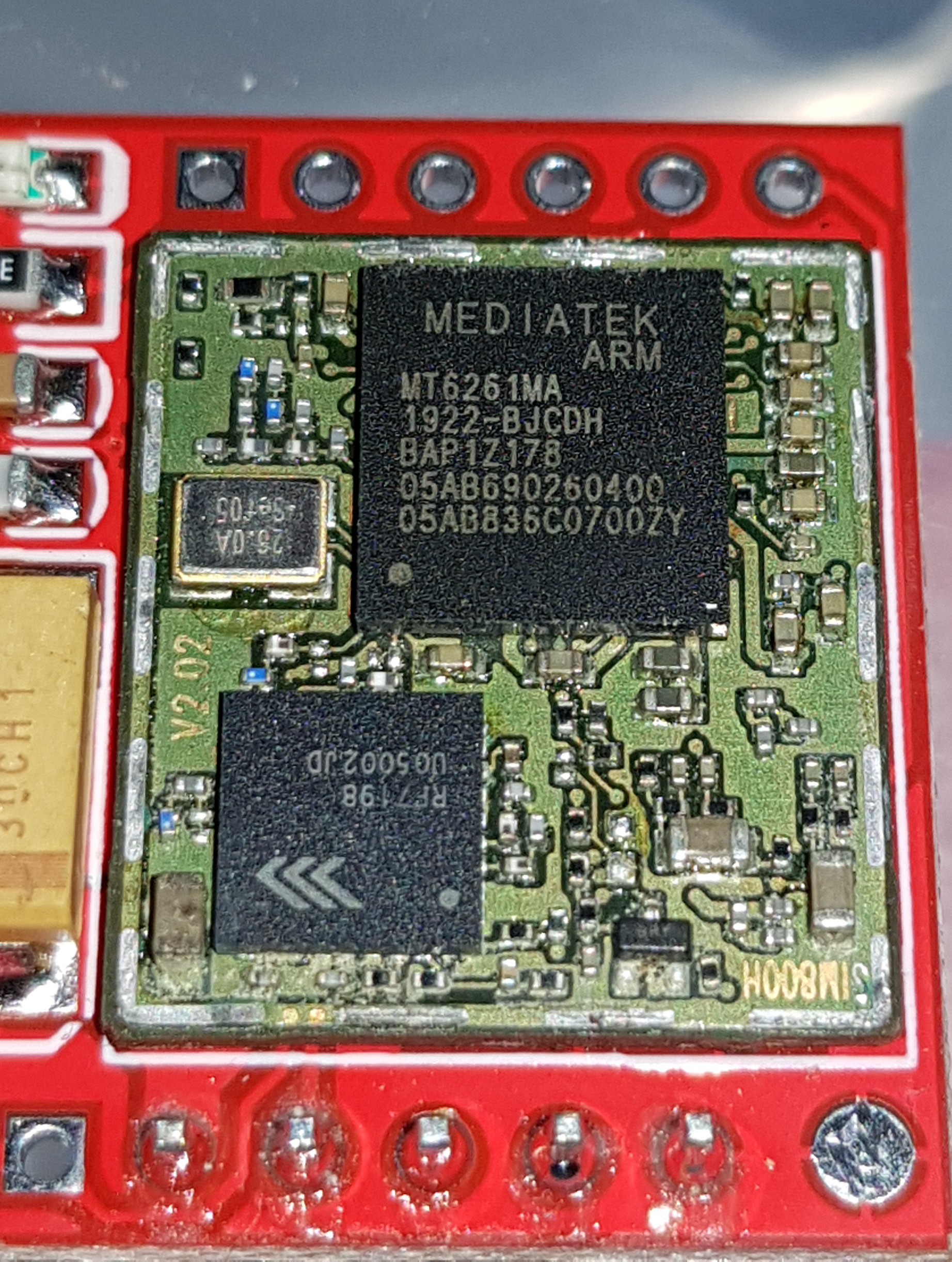
This is the internal photo of the SIM800L module. The above SIM800L module is having MT6261MA and RF7198 IC and having a 26MHz oscillator. If we note the SIM800H marking seen on the bottom right corner. It looks both SIM800L and SIM800H uses the same layout and the functions are manipulated either by software or hardware with same footprint or ICs.
As we know these ICs are not single die silicon process. instead depends on what function we need, the multiple ICs were placed and bonded together.

This is the X-Ray image of MT6260 IC which clearly shows that it consists of multiple dies and bonded together inside.
A sharp eye can pick out the outline of multiple ICs among the wirebonds. Image credit: Nadya Peek

The above is a simple block diagram of MT6261 family processor. We can see this IC supports GSM/GPRS, Bluetooth and FM.

Both SIM800L and SIM800H shares common footprint. Pin 36 for SIM800L is NC and SIM800H uses as BT antenna.
SIM800H module with FM and Bluetooth:
There are application notes available in english for both FM radio and Bluetooth with available AT commands.
SIM800 modules supports embedded AT commands which eliminates the extra host for simpler tasks. But how to program the module using Embedded AT develepment environment is unclear and poorly documented.
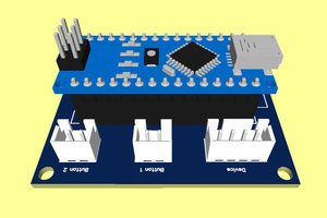
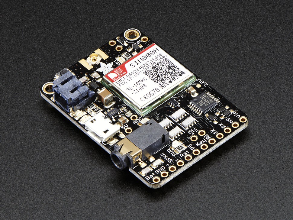
But there are commercially available modules with SIM800H module along with Atmega32U4 IC for easy arduino based programming.

The above board is having both SIM800H module and atmega32U4 processor. Below the module you can see the provision for connecting MIC and Speaker. The board operates on single Li-Ion battery with nominal voltage of 3.7V. The connection between the processor and the SIM module is through Tx and Rx lines along with few more control lines for power ON/OFF etc.,
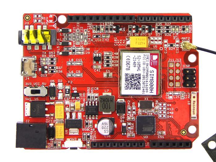
Seeeduino GPRS module with SIM800H and Atmel 32U4 IC. You can also see the Bluetooth antenna apart from GSM/GPRS antenna. For FM the earphone leads acts as the FM antenna.
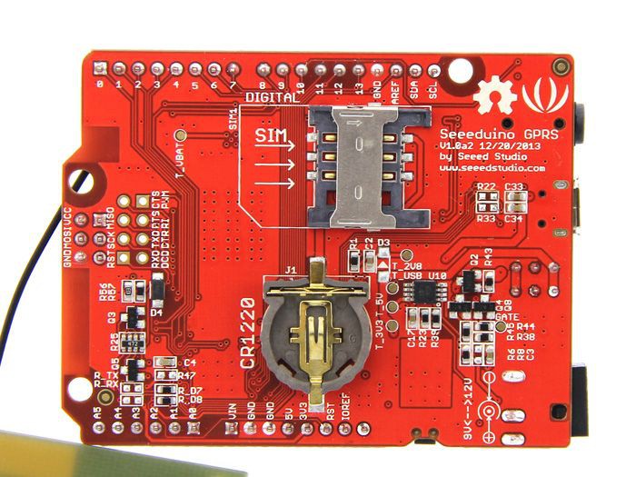
Bottom side view with SIM card and CR1220 battery for RTC backup.
Another module having SIM800H without any microcontroller on board. But Tx and Rx pins are available with convenient voltage level shifters to adopt to various logic levels.

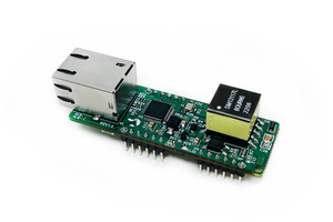
One more SIM800H module used with GSM3 Click.
FM arduino code using SIM800L and SIM800H
#include <fm.h>
#include <SoftwareSerial.h>

int channelButton = 5; //used for changing channel
FM fm;

void setup() {
    pinMode(channelButton,INPUT);
    Serial.begin(9600);
    Serial.println("FM Test...");
    fm.preInit();
    while(0 != fm.powerOn()){
        Serial.println("FM power on failed, try again...");
        delay(2000);
    }
    fm.setVolume(6); //0,1,2,3,4,5,6
    fm.scanChannel();
    Serial.println("FM init success");
}

void loop() {
    while(HIGH == digitalRead(channelButton)){
        delay(50);
    }
    Serial.print("change Channel\r\n");
    fm.channelNext();
    while(LOW == digitalRead(channelButton)){
        delay(50);
    }
}
In this sketch we are using digital input D5 for frequency selection and the volume is fixed at level 6.
FM radio with SIM800H using Bluetooth:
#include <bluetooth.h>
#include <SoftwareSerial.h>

#define DEFAULT_TIMEOUT 5
#define BT_BUF_LEN      32
BlueTooth bluetooth;

char bluetoothBuffer[BT_BUF_LEN];
int start = 0;

void setup() {
    Serial.begin(9600);
    Serial.println("Bluetooth AT Command Test...");
    bluetooth.preInit();
    delay(3*1000);
    while(0 != bluetooth.powerOn()){ //bluetooth PowerOn
        Serial.println("bluetooth power on failed, try again...");
        delay(2000);
    }
}

void loop() {
    if(bluetooth.serialSIM800.available()) {
        start = 1;
    }else{
 delay(...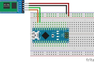
 Silícios Lab
 MinerMiller