Close
0%
0%

PCB Assembly Desktop Factory

Creation of ready-made low-budget infrastructure for developing, manufacturing, and adjusting electronic devices

Public Chat
Similar projects worth following
Project goal
Creation of a ready-made low-budget infrastructure for developing, manufacturing, and adjusting electronic devices with microcontrollers and FPGAs in single and small quantities in a "garage" or a small production.

For: amateurs, hobbyists, enthusiasts, and fans interested in quick single and low-volume production of electronic devices.
For: Professionals interested in quick prototyping of electronic devices.

Hard. Descriptions, instructions, diagrams.

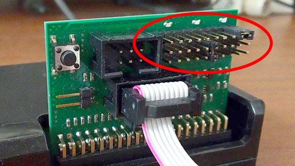
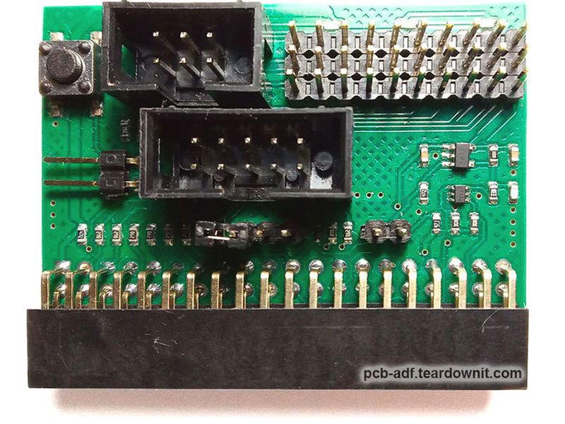
  1. Unified extension board for Raspberry Pi microcomputers. The board is designed primarily for programming and debugging microcontrollers and FPGAs. Still, it can also be used as an interface for various devices.

    The board has built-in elements:
    · Universal connector for our target system adapters
    · A connector for connecting buttons, foot buttons, and pedals for mass production
    · Multicolor LED indication for displaying modes and stages of device operation, also for mass production
  2. Our adapters for connecting various microcontrollers, FPGAs, and target systems based on them to a unified extension board.
  3. Complete electronics kit for converting serial ovens into a solder paste reflow oven (sensor and power parts).
  4. Ready-to-assemble solder paste reflow oven.

Soft. Deb-repository of ready-to-use instructions, applications, and out-of-the-box solutions

  1. Software packages and scripts for working (programming, verification, debugging) with microcontrollers, FPGAs, and target systems based on them via a unified extension board.
  2. A script shell for organizing an automated, repeatable process for programming several identical microcontrollers, FPGAs, and target systems based on them via a unified extension board.
  3. Applications and script packages for PCB assembly:
    · Navigation package for mounting SMD components on PCB.
    · Packages for preparing and cutting Darcon stencils for solder paste application.
    · Package for controlling solder paste reflow oven electronics kit

  • Pi Extension board "PiEBridge" adapters

    teardownit12/28/2023 at 15:47 0 comments

    Programmable power supply for external/target devices

    The PiEBridge has a built-in programmable power supply for external/target devices. The user can set the voltage of 2.5-5V (accuracy not less than 2%) with a current not more than 300mA by command from SBCs (e.g., Raspberry Pi).

    Users can set this programmed voltage or "ground" to any pin of the output connectors using the built-in 3*10 pin matrix and jumpers.

    Connectors

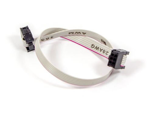
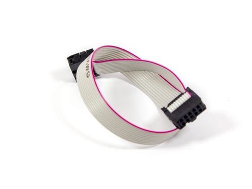
    The PiEBridge extension board has built-in 6-pin IDC (2x3 0.1") and 10-pin IDC (2x5 0.1") output connectors.
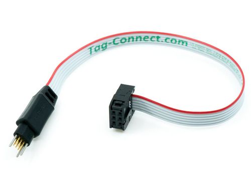
    We recommend using four basic adapters to connect to target systems (e.g., for flashing) via these connectors:


    IDC6-IDC6

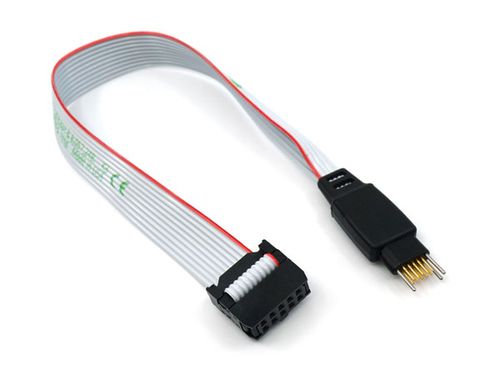
    IDC6-TC2030

    (Tag Connect 6 pins)


    IDC10-IDC10


    IDC10-TC2050

    (Tag Connect 10 pins)

    Analogs in Segger adapters

    PiEBridge adapterConnects to:Segger adapter
    IDC6-TC2030PCB pads, no mating connector required on PCB
    Users who do not use any standard for
    connector pinout can program all chips
    with compact programming interfaces
    having 6 or fewer circuits - SWD, SWIM, SPI, etc.
    6-Pin Needle Adapter
    IDC10-IDC10the 10-pin 100-mil Intel FPGA JTAG connectorIntel FPGA Adapter
    (formerly J-Link Altera Adapter)
    ---Silicon Labs evaluation boardsSiLabs C2 Adapter
    ---the SWIM connector and a standard 10-pin connector (STM8)STM8 Adapter (IDC10)
    IDC10-TC2050PCB pads, no mating connector required on PCB10-Pin Needle Adapter

  • Our team

    teardownit12/13/2023 at 11:40 0 comments

    We have many years of experience in developing electronic devices for various customers. When we complete a non-standard task, we often explore new methods and ways to achieve the required result. By accumulating this knowledge, we create solutions to simplify the design and creation of devices. It's time to share some of our solutions with the community now.

    Core team:

    • 3 full-time hard/firmware engineers
    • 15-30 years in product R&D and systems engineering
    • full range of product development jobs
      - highlighting the problem
      - transforming it into a task
      - searching for possible solutions based on target parameters
      - analysis and selection of the best option

    Application and system programming:

    • core team programming languages: C/C++, ASM
    • compilers: C /C++ (CLI): GCC, IAR, SDCC, C++ Builder, Avocet C, Hi-Tech C
    • IDE: SlickEdit, emacs, IAR Embedded Workbench, Multi-Edit, eclipse cdt, STM32CubeIDE, Atmel Start, Atmel Studio, NetBeans IDE, Qt Creator
    • make, cmake, qmake, cvs, subversion, git, etc
    • experience/projects:
      - embedded programming z80, MCS-51, AVR, PIC, ARM (7, 9, Cortex), STM8
      - RT-tasks under eCos
      - eCos modules
      - in-house RTOS for telecom equipment
      - special Windows-NT services for own hardware
      - BDOS/BIOS CP/M for Z80CPU hardware emulator
      - desktop applications for Windows/Linux

    Circuit engineering:

    • analog: automation, data acquisition, measurements, sound, etc
    • digital: from simple logic circuits to FPGA/MCU/PSoC
    • power electronics: experience in DC/DC up to 600W
    • experience: PSpice, VHDL, Verilog

    Electronic devices R&D:

    • PCB/PCBA TH/SMD/multilayer w/auto testing @ production cycle
    • PCBA (bare and cased) thermal calculations
    • calculation and design of pulse transformers and inductors
    • 3D housing design
    • experience: KiCAD, Altium Designer, FreeCAD, OpenSCAD, Fusion360
    • projects:
      - wide spectrum of microcontrollers
      - telecommunication equipment (about 1M subscribers in service)
      - time measurement equipment for telecom
      - hardware emulator with a signature analyzer

  • Pi Extension board "PiEBridge"

    teardownit11/24/2023 at 04:37 0 comments

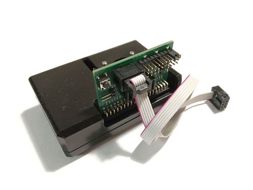
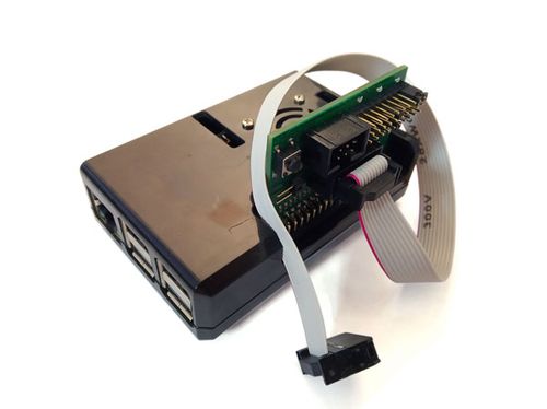
    "PiEBridge" is an expansion board for microcomputers similar to the Raspberry Pi (Pi), which is designed to be a helper for the DIY-maker in all his activities - Pi, together with PiEBridge, can perform a variety of functions:

    • universal programmer
    • software and hardware debugger for target systems
    • PCB fusion furnace controller
    • smart-home controller
    • as well as do many other useful things
    You might say Pi already knows how to do these useful things, so why does it need more extension boards? Here is the answer to that question:
    • PiEBridge transforms the Pi's 40-pin I/O subsystem into more practical 6/10-pin lines for many applications and provides signal integrity for these lines
    • adds the simplest controls and indications (button, pedal, and LEDs)
    • has a programmable 2.5..5V power supply for external devices

    "Naked" Pi is usable in two extreme configurations - either just a box controlled externally via SSH or a desktop computer with a monitor, keyboard, and often even a mouse. In addition to these typical use cases, PiEBridge allows you to use the Pi as a standalone software automaton to perform random repeating tasks with minor interactive operator participation.

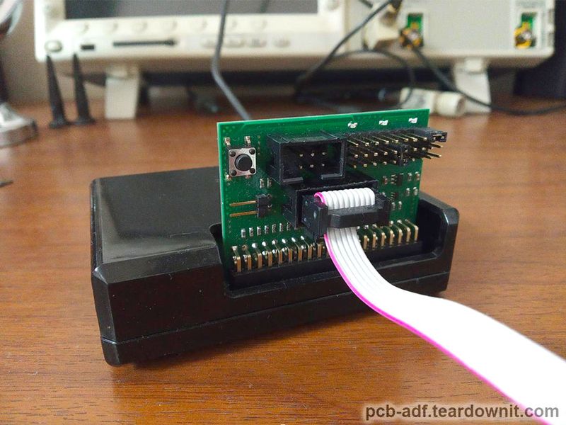
    PiEBridge is plugged into the Pi expansion connector (compatible with family models with a 40-pin connector) and installed vertically. For this purpose, the Pi case (if available) must have a corresponding cutout on top.

    When used as a programmer, PiEBridge can work with most known 6-pin and 10-pin connectors, and GND and Vcc can be randomly connected to their pins to ensure compatibility.

    The programmable power supply for external devices is programmable on/off and programmable in the range of 2.5 - 5V with an accuracy of about 2%.

    Deb-packages for PiEBridge have been created and compiled into a repository:

    • general-purpose, providing configs and libraries for working with controls and indications, as well as with the power supply
    • special purpose, e.g., applications for MCU and FPGA programming and debugging
    • auxiliary purpose, for example, for repeating operations automation (like mass-production function for firmware flashing). In this case, the user can use settings that provide autonomous launching of the necessary software when the Pi is turned on, and then (after finishing its work) its simple parking and shutdown by pressing and holding the button for a long time.
    • metapackages, which cause installation of necessary software and configs for the selected role and allow to simplify preparation for work

  • About project. Project Objectives

    teardownit11/13/2023 at 06:23 0 comments

    The first project objective is to create extension boards for Linux microcomputers with GPIO, containing minimal indication and control elements and a small connector for connecting external devices with unified access to them.

    Why do you need a board like this?

    1. In most practical applications, the extension connectors of these microcomputers are redundant. For example, a cursory review of published Raspberry application projects shows that you will often find that 10-pin will suffice.
    2. For the same reason, the same 40-pin connector is impractical (and more often - simply impossible) to install in the target device, and this means that somewhere, there must be a transition, a bridge to a smaller connector.
    3. Serial matching is very useful (and sometimes necessary) when connecting devices, for which, for example, Segger has a special adapter. Raspberry has no matching elements, so they must be placed somewhere. By the way, these elements (resistors) are useful for another important reason - they effectively reduce the risk of GPIO damage.
    4. A microcomputer, equipped with a minimalistic interface on a few LEDs and buttons, is freed from the monitor, mouse, and keyboard from the constant "tutelage" of the host-PC and becomes a handy standalone tool for a pervasive class of routine and cyclic tasks, such as:

      - programming, diagnostics (JTAG interface provides access to various pins of the chip, which allows the creation of the necessary test conditions (logic levels on the pins) and reading the states; general tests are also possible),

      - electrical training (test (usually cyclic) operation of the device in specified modes. For example, at the initial moment of the device lifetime, detection of hidden defects is most possible (semiconductors, switching, etc.), so "runs" of devices in the correct modes at the factory and workshop are necessary to ensure that consumers receive the best quality devices by filtering out defective devices back at the factory), etc.

      In fact, for example, what does the flashing process of a stack of assembled boards consist of? It consists of a sequence of actions: "plugin, start programming, wait, on a pass/fail signal, move to cell number either 1 or number 2, go back to the beginning". Ideal for a button and three LEDs.

    The second project objective is to create a thematic repository with software a tool/infrastructure for easy and simple installation and updating of the required application/package.

    The third project objective is to create and place in the repository thematic packages designed to facilitate installation and configuration, as well as application packages that solve independent tasks.

    Already configured apps/packages, working scripts for apps with already configured pins and adapters for the right adapters.


    Now we have a device that, first of all, is very versatile, and secondly, whose total lifetime should be much longer than the devices from our museum. It can be a classical programmer, working by command from a PC; it can be an autonomous device, able to program, test, and reject independently.

    At the same time, the project's area of interest has expanded to the whole field of development, manufacturing, and testing of electronic devices - for example, you can install from our repository a package for cutting Dacron stencils with a plotter and use our know-how in working with such stencils. You can make or order a furnace for melting SMD components.

  • About project. History and creation reasons

    teardownit11/13/2023 at 06:10 0 comments

    The project was created by accident at the moment of urgent need for a mobile standalone device for ISP programming and testing a lot of printed circuit boards with controllers and FPGAs. The task was quickly solved on a Raspberry by assembling a small IDC-10 socket adapter with a button and LEDs on a breadboard and installing OpenOCD and xc3sprog packages.

    It became a solution, after which any thoughts about buying or upgrading another programmer just disappeared. In fact, if you have been working with programmable devices for a long time, you can surely find a whole museum of such devices for flashing (I have a whole drawer of them on my nightstand) - ByteBlaster, Segger, (maybe even several), ST-Link, etc., but there are many of them! These devices are built for LPT, COM, USB... lots of different ones, but here's the trouble - many are already old, unsupported, and incompatible. We'll have many more other reasons to finally buy a new one already. You know? And instead of all this happiness!

    The advent of small and low-cost Linux microcomputers with GPIOs has allowed desktop applications to access external devices without special adapters, dongles, etc., leaving only electrical matching necessary.

    Many projects immediately used this opportunity but also immediately raised the problem of unification on the use of GPIO (lack of unification). And this requires a solution.

View all 5 project logs

Enjoy this project?

Share

Discussions

Similar Projects

Does this project spark your interest?

Become a member to follow this project and never miss any updates