 tobychui
-
1Send the PCB to Print
The PCB is the main component of the build. So the first thing you want to do is send the PCB to print. Some manufacturer provide free printing services of 1 board per month. If you have a chance to get such promotion discount, you can get a PCB for nearly free of charge.
You can get the PCB Gerber file here
https://github.com/tobychui/4xMacropad/tree/main/4x5Macro-Numpad/PCB
I am printing mine in white just to match my 3D printing filament and keycaps.
![Send the PCB to Print]()
-
23D Printing the Body
The numpad base is compose of two parts. The first part is the part that cover the back of the PCB. The other part is the tilting platform that the base plate is mounted on. You can edit this part to adjust to fit your primary keyboard tilting angle or just not using it at all if you prefer your numpad to lie completely flat on your tabletop.
You can get the 3D model files here or with the links below (or see the project file section)
https://github.com/tobychui/4xMacropad/tree/main/4x5Macro-Numpad/3D%20Model
The two pieces are held together using 4 M2x5 screws.
If you are planning to use the standard numpad arrangement, remember to print the switch stabilizer as well. It help keeps the 2U switches (enter, 0 and +) stable and not moving when you press the switch down.
![]()
![]()
-
3Populate the PCB
![]()
![]()
![]()
![]()
![]()
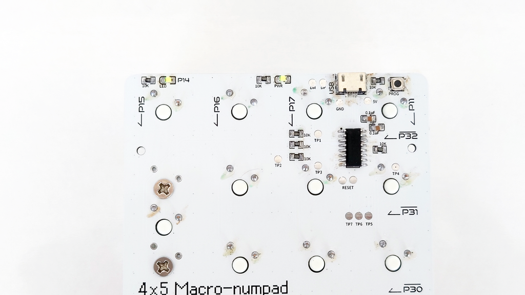
After the parts that can be out sourced to factories, now it is the hand crafting parts. Follow the diagram above to solder the parts in place. This will allow the MCU to perform a grid scanning on all the switches by activating each row (LOW activated) and read from each column (when the read is LOW, means that active row's reading column button is pressed).
![]()
This diagram showcase the simplified circuit diagram of the PCB, in which the rows are low activated instead of the normal high activated. This design can save 1 10K SMT resistors compare to HIGH activated design, and therefore making the BOM list identical as the previous macropad design.
-
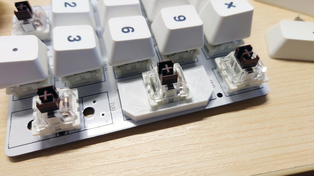
4Soldering the Switches
![]()
![]()
This numpad can be used as a macro-numpad if you populate all the 20 switches, or as a standard numpad if you only solder the 17 switches. Of course, you can always pick any number of switches in between like having one "0" and one "00".
-
5Installing Switch Stabilizer (Optional)
If you are using the standard numpad layout and solder only 17 switches, you might want to add the stablilizer parts to make the switch not wiggling around when pressed on the edge of the keycaps.
You can screw the stabilizer pieces in place using 2 M3 x 5 screws using the unused hole for the switches itself.
![]()
![]()
![]()
-
6Modify Firmware and Upload
You can find the firmware in the link below.
https://github.com/tobychui/4xMacropad/tree/main/4x5Macro-Numpad/firmware
By default, it act as a standard numpad or numpad + media controller (i.e. with the previous 4x macropad mode A default code integrated). However, if you decided to change the code to fit your need, you can edit the actions.ino. Each keys with col and row id are commented in code, which corresponding to the silk screen printing on the PCB. Each keys has its dedicated keydown (activate when the key is just pressed) and keyup (activate when the key is just released) function. You can feel free to modify the code to make any key press event you want!
If this is the first time you are programming a CH552G device, be sure to install the board manager for this MCU from the Github link below and follows its driver installation steps.
https://github.com/DeqingSun/ch55xduino
![]()
![]()
To upload the firmware to the numpad, follow the steps below (timing is important!!!)
- Press and hold the PROG button
- Click "Upload" in your Arduino IDE.
- When the sketch has finished compiled and ready to upload, insert the USB cable into your numpad and release the PROG button (Timing is important)
- Wait for the firmware to finish upload
- Unplug the numpad and plug it back after a few seconds for it to reset
- Test if the numpad is working by pressing random keys on the numpad
![]()
-
7Assemble the Numpad
![]()
There are 4 (or 3) screws hole where you can attach the PCB to the case. Screw in a few M2 x 5 screws into the hole onto the PCB into the base plate and secure the whole unit in place. You can also stick some foam tape to the bottom of the case to make it less slippery on your table.
-
8Your $8 Mechanical (macro) Numpad Is Completed!
Now you got yourself a $8 cool little numpad that you can play around!
All of the materials, design files and 3D model can be found on my Github repo over here:
https://github.com/tobychui/4xMacropad
Feel free to build one and share it with me :)
![]()
![]()
![]()
DIY $8 Mechanical Numpad
DIY $8 Mechanical Numpad (with Arduino Compatible Firmware!) and how I optimize it for international shipping


Discussions
Become a Hackaday.io Member
Create an account to leave a comment. Already have an account? Log In.