WJCarpenter
-
Two friendly boxes
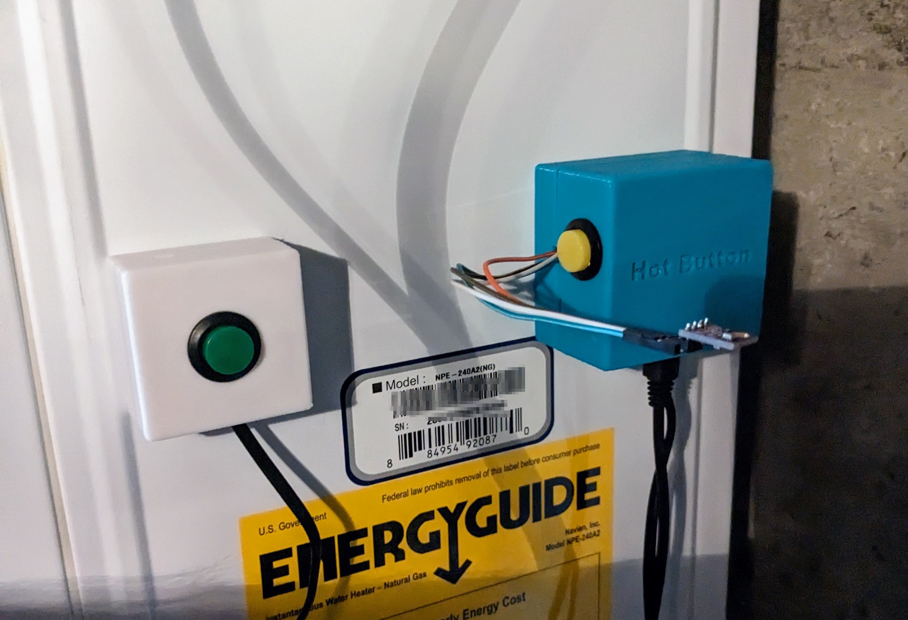
09/20/2023 at 01:56 • 0 commentsAll parts assembled and put in place.
![]()
The teal box with the yellow button is the D1 Mini with the relay. The part dangling out on thin wires is the BME280 climate sensor. The white box with the green button is the button wired directly to the HotButton terminals of the water heater.
-
Two minute warning
09/18/2023 at 02:42 • 0 commentsYou might have noticed in that previous project log that one of the DIP switches enables/disables the energy saver function. I now know that it's enabled by default, but I also know how to disable it. The principal function of the energy saver feature is to limit the runtime of the recirculation pump to 5 minutes. My installer told me that's really for the benefit of California residents due to some kind of energy compliance regulation. I'm not sure how long it took my old recirculation pump to get all the way to the bypass valve, but I think it was more than 5 minutes. I spent some time thinking about how I might get Home Assistant to push the button multiple times, but that was before I found out that I could easily disable it and get as many minutes as I might need.
Not to worry. I have since timed it. From completely cold to shutting off the bypass valve, it takes just over 2 minutes (somewhere between 2:05 and 2:10). When standing by the sink that has the bypass valve under it, I can hear the water rushing through it until it closes off. That, and the short period of time, tells me that the recirculation pump in the Navien NPE-A2 is pushing a significantly higher flow rate than my old recirculation pump.
There is one other interesting detail in the recirculation configuration. It's kind of well-known even though it's not that obvious. There is a setting for the distance (in pipe feet) from the heater to the far fixture. The default is 30 feet. Regardless of the time setting, the Navien will stop pumping when it thinks it has pumped that many pipe feet of water. Everybody who looks into this and wants to use a time limit sets that distance value to something really high, like a few hundred feet. There must be some scenario where using that distance setting makes sense, but I don't know what it is. If you are using a bypass valve, then you want to pump until the bypass valve closes. If you are using a closed loop system, where the hot water comes back to the heater, there are temperature sensors and configurations to control that. Maybe the distance thing is intentionally redundant, just like using a timer along with a bypass valve.
Since it only takes 2 minutes to get hot water at the far fixture, and since I have the M5 Atom Lite call button devices in the two upstairs bathrooms, I'm going to skip setting up some kind of scheduled recirculation, at least for the time being.
-
Press OK to Cancel
09/18/2023 at 02:21 • 0 commentsI've got my electronic button pusher all wired up now. Along the way, I found a couple of confusing things in the Navien NPE-A2/S2 installation manual. In the end, it turned out to be completely accurate, but it was still confusing. When I first wired things up and tried to configure it via the front panel, it refused and asked me if I had connected the HotButton and had set the DIP switch to enable it. "Well, heck, yeah," I thought. I assumed all along that the HotButton itself was a simple NO momentary switch, but I began to wonder if it had some kind of secret internals, like some particular resistor value so the heater would recognize it. That would be overly complex, but it's at least possible. I wrote to the company to ask about that. I haven't heard back yet (it was late on a Friday that I wrote to them, so I didn't expect an immediate answer). In the meantime, I figured it out.
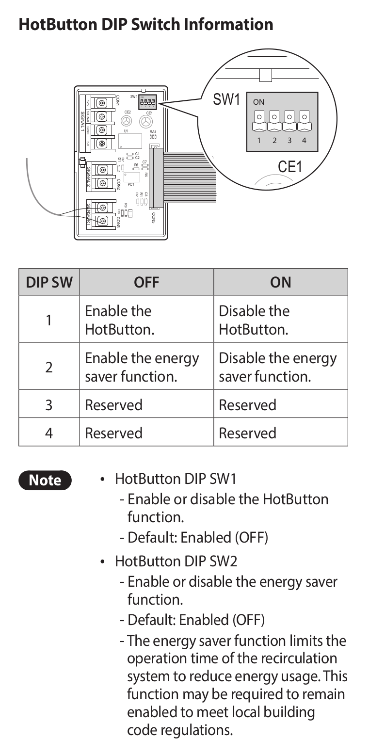
Here's part of the installation manual:
![]()
In the first place, the image of the board is rotated 180 degrees from its actual position inside the heater. I wasn't really fooled by that trick since I have plenty of experience being fooled by it in electronics vendor documentation. So, even though it's highlighted showing the up direction of the DIP switches being "on", I rotated my brain and knew that down meant "on". (The other fun thing about that image is that they show a pair of wires coming in to unrelated terminals.) What actually fooled me was something I had to read about 50 times before noticing. You need to have the DIP switch set to "off" to enable the feature. It's right there in black and white. I had carelessly misread "Default: Enabled (OFF)" to mean "by default enabling the feature is turned off". I had flipped the switch to "on" and thereby disabled the HotButton feature.
I have to at least partially blame myself for that one. But just so I don't leave Navien unblamed too much, why in the world is the menu configuration for the HotButton (and recirculation in general) behind the password-protected "Installer menu"? Luckily, my installer kept the default published password of "1234". If you just read the user manual instead of the installation manual, you wouldn't know any of this. At least Navien does publish all the manuals as PDFs that anybody can download.
-
Magnets
09/17/2023 at 18:16 • 0 commentsI didn't think about it until the water heater was actually being installed, but the outside case of it is sheet metal. It's some kind of steel. So, I started thinking about using magnets to place the relay enclosure on the side of the heater.
My first attempt was to use one of those rubbery refrigerator magnets that advertisers send us all the time. I cut up one of them (for something that we never have and never will use, but we have their magnet on our refrigerator) to exactly the size of the enclosure footprint. I use cyanoacrylate (CA) glue (aka, superglue) to attach it to the enclosure. In a test, the base stuck pretty well to the side of the heater, but when I added the top with the electronics, it was a very weak bond. It was way too easy to move it around, and I imagined that vibration and gravity would eventually drop it off the side and onto the floor.
I have some small, round rare earth magnets on hand. They are called rare earth magnets because it's what NASA uses to airlift elephants and whales to the moon. Those beauties are strong. If you don't have any experience with them, you might not know that it can take two men and a boy to pull two of them apart. If you don't have that kind of labor force handy, you get them apart by sliding them, and even then it's a struggle. If you relax your grip for even a second, they jump back together and laugh at you.
I used CA glue to attach 3 doughnut-shaped magnets, 4-5 millimeters each, to the already-attached rubbery magnet. As I expected, that made an incredibly strong bond with the heater case. I had to slide the enclosure to an edge of the case to pull it off. I thought that pulling it straight off might damage the enclosure base itself. Needless to say, for the intended use, this was a complete success. The aesthetics weren't fantastic since there was a gap of a couple millimeters (the thickness of the magnets) between the enclosure base and the heater case. For this kind of project, out of the way in the basement, that was not a big deal. It bugged me a little, but it's the kind of thing that only I would know about.
For more general reasons, I wanted to see if I could figure out how to embed the magnets into the bottom of the enclosure base. That might be more meaningful in some future project. Using the YAPP template, I had already made openings for screw holes. It was a simple matter to change the size of those to the diameter of some of my rare earth magnets. I took the opportunity to fix the spacing of the holes, and I also made it configurable to make holes for magnets, holes for screws, or neither.
It's one thing to have a hole the right size for a magnet. It's another thing to keep the magnet in that hole. I wanted to have a thin layer of 3D printed material covering one end of the magnet cavity. If I put the covering at the top of the hole (on the inside of the enclosure), then it could create problems with the 3D printing process, possibly requiring supports. I decided to put the covering on the bottom (on the outside of the enclosure) to avoid that potential problem. That would also hide the magnets, which I think is aesthetically better. The magnets are strong enough that I wasn't worried about them having to act through that small distance, and a bonus was that the magnetic force would tend to keep the magnets pressed into the cavities.
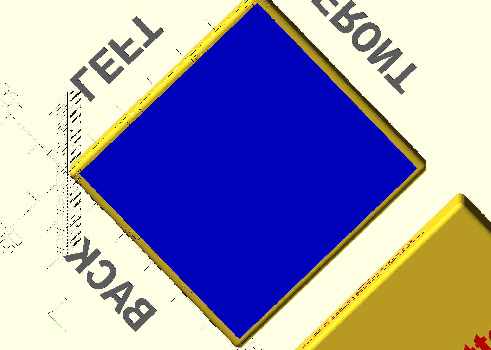
The YAPP template doesn't have anything for a cut-out that doesn't go all the way through some face of the enclosure. I figured out that I could put a thin layer entirely covering the base of the enclosure after YAPP had already done all its work. The end of the OpenSCAD file now looks like this:
//---- This is where the magic happens ----
YAPPgenerate();
if (hbrb_use_magnets) {
  color("blue")
    translate([hbrb_wall_border,hbrb_wall_border,0])
    cube(size = [shellLength-(2*hbrb_wall_border),shellWidth-(2*hbrb_wall_border),hbrb_magnet_bury_thickness], center = false);
 }
Here's what it looks like from the bottom, rendered in blue:
![]()
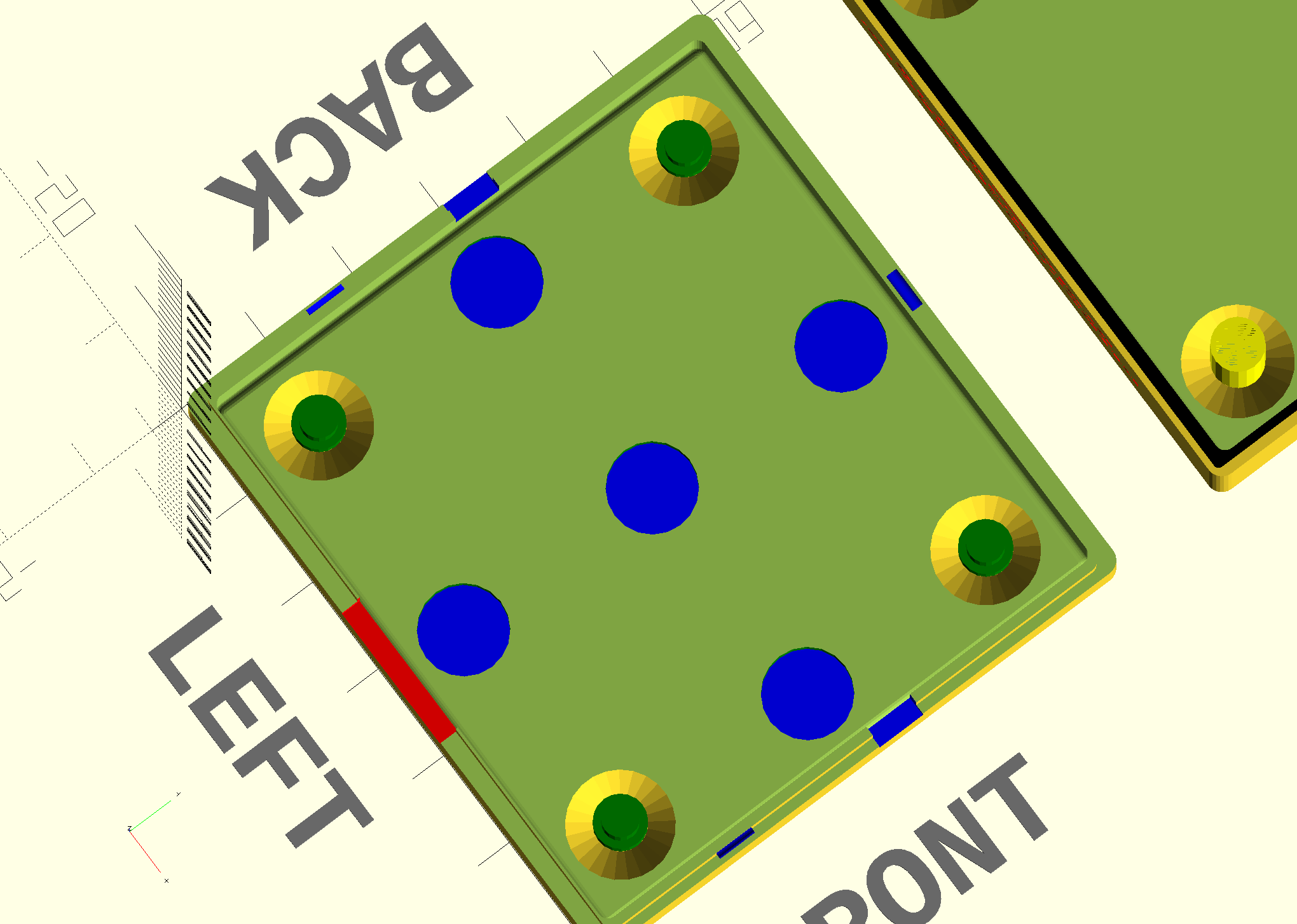
Here's the same thing viewed from the inside:
![]()
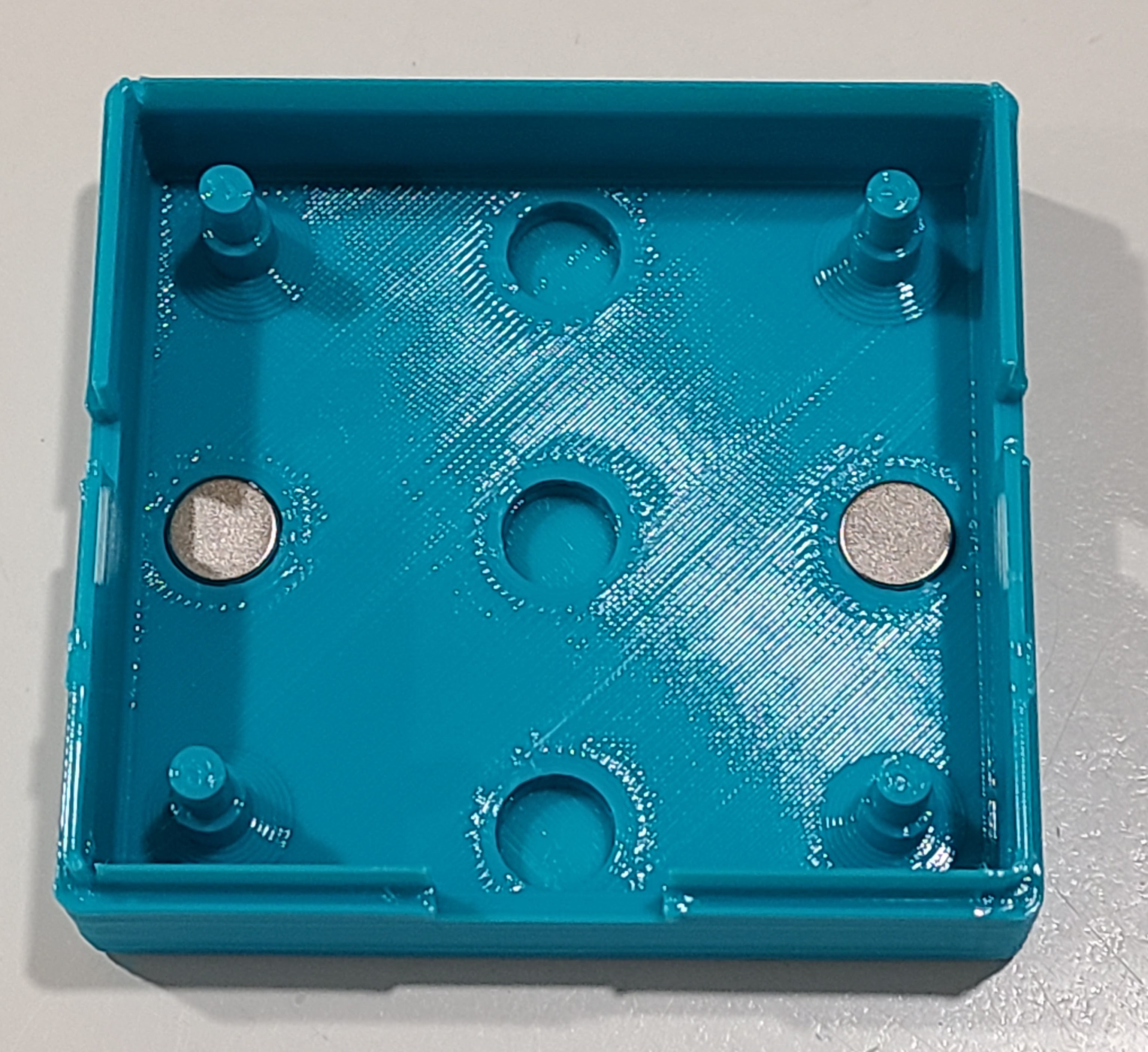
I made the magnet holes just slightly larger in diameter than the magnets and secured the magnets in place with CA glue. Here's the printed result:
![]()
Even though I adjusted the thickness of the base floor to account for both the thickness of the magnets and the thin layer that I added, the magnets still stick up above the inside floor ever so slightly. That's because I didn't account for the shrinkage of the filament during printing. It wasn't significant enough for me to adjust and print it again.
On my first attempt, I tried to make the thin layer covering the magnets 0.5 mm. I was careless in my thinking though. With my 0.28 mm layer height, that resulted in just a single printed layer. I'm a little afraid that those strong magnets might try to pull through that single layer, so I adjusted my numbers to get two layers of printed material. I could have done something to adjust the thickness of the first layer in my slicer, but I didn't want to fool around with that.
I was so pleased with how that turned out that I decided to make a second enclosure to hold a pushbutton that I would wire in parallel to the contacts inside the water heater. Recall that the pushbutton on the relay box enclosure goes through the electronics and exercises the complete automation. This second button would be directly wired to the water heater and would be a DIY version of Navien's HotButton add-on. I modified the OpenSCAD file to make it configurable which enclosure to render. It was mostly a matter of conditionally setting various dimensions and making cutouts and engravings conditional.
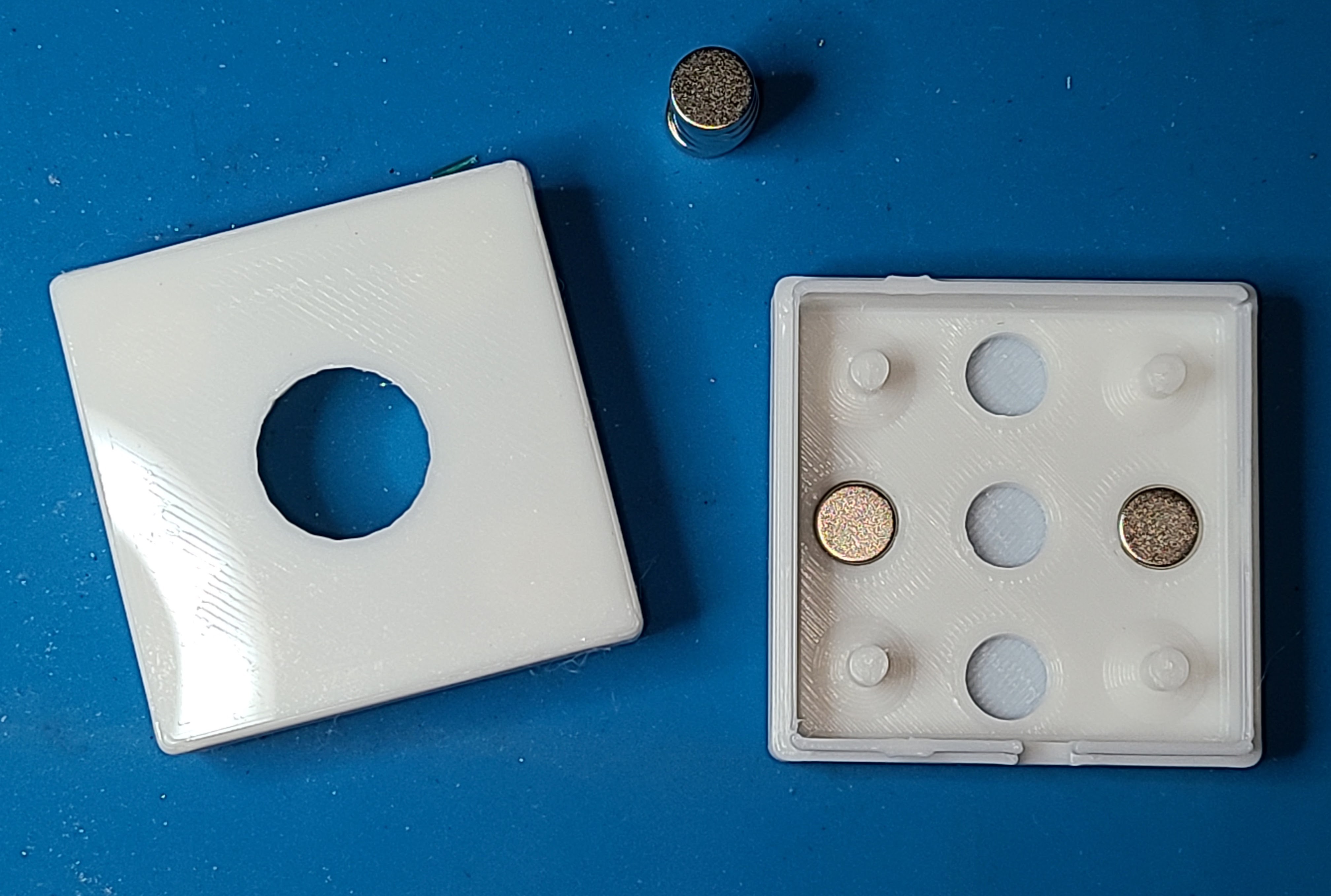
Here's that printed enclosure. It's a bit smaller and the cutout for the button is in the more traditional top of the enclosure.
![]()
All in all, I'm pretty pleased with the results of this and will certainly use it other ways in the future.
-
Some automation tweaks
09/14/2023 at 01:33 • 0 commentsFirst of all, I forgot that by default a Home Assistant sequence of actions will stop if one of the actions produces an error. I was reminded of that when one of my two Atom devices wasn't plugged in when I was testing the other one. Doh! There are two ways to deal with that. You can mark an action as "continue_on_error", or you can nest the actions inside a "parallel" operator. Because the actions that I can ignore are independent of each other (calling services to fiddle with the LED on the Atom devices or the D1 Mini), I chose to make them parallel.
I took all of the actions in my automation and moved them to a script. That gives me the option of calling the script from a triggered automation (such as a button press on an Atom device) or from some other Home Assistant mechanism. I know I will do the former; for the latter, I may use it to implement scheduled hot water recirculation.
I set the mode of the script to "queued" so it can be executed serially no matter if the calls to it are overlapped during the script's built-in time delay. If the normal time for running the recirculation pump is 5 minutes, then running the script twice will give 10 minutes without the caller having to wait around. To run the pump for an hour at some scheduled time, I can just call the script 12 times (assuming I have set the queue limit high enough). Since the triggered automation now just calls the script, it doesn't matter too much what its mode is. Or, rather, there is no setting that is ideal for all scenarios. I settled on setting it to parallel mode.
I mentioned earlier that I set the delay to 15 seconds for testing. I have now split that into two separate time delays. For testing, it's 5 seconds and 15 seconds. Why did I do that? A feature of the Navient HotButton mode is that additional button presses are ignored while the recirculation pump is running. The first time delay will be set to match whatever I configure on the water heater, which is some whole number of minutes. The second time delay is just a little extra padding to make sure I don't push the button slightly before the end of the water heater's timer and have it ignored. I could have combined them into a single larger timeout, but this way makes the padding a little bit more explicit, and I'm less likely to forget to have it.
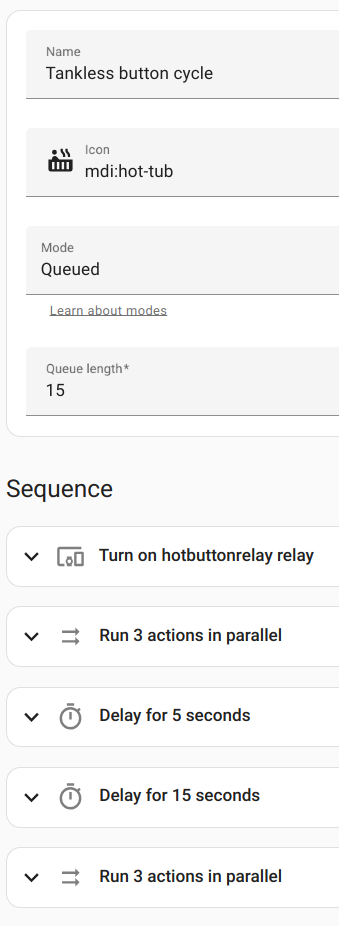
Here is what the script looks like:
![]()
And in YAML:
alias: Tankless button cycle
sequence:
  - type: turn_on
    device_id: 631ea0d418d7508fdbf35e046f077906
    entity_id: 556da559467ce707e6dd9f6c5ad39797
    domain: switch
  - parallel:
      - service: esphome.hotbuttonkb_set_led_hot
        data: {}
      - service: esphome.hotbuttonmb_set_led_hot
        data: {}
      - type: turn_on
        device_id: 631ea0d418d7508fdbf35e046f077906
        entity_id: 2a370e76eeb5971f48e70e2f75f500e7
        domain: switch
  - delay:
      hours: 0
      minutes: 0
      seconds: 5
      milliseconds: 0
  - delay:
      hours: 0
      minutes: 0
      seconds: 15
      milliseconds: 0
  - parallel:
      - service: esphome.hotbuttonkb_set_led_cold
        data: {}
      - service: esphome.hotbuttonmb_set_led_cold
        data: {}
      - type: turn_off
        device_id: 631ea0d418d7508fdbf35e046f077906
        entity_id: 2a370e76eeb5971f48e70e2f75f500e7
        domain: switch
mode: queued
icon: mdi:hot-tub
max: 15
Of course, the automation is correspondingly simpler:
![]()
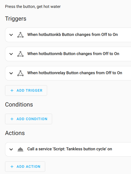
and in YAML:
alias: Tankless hot button description: Press the button, get hot water trigger: - platform: state entity_id: - binary_sensor.hotbuttonkb_button from: "off" to: "on" - platform: state entity_id: - binary_sensor.hotbuttonmb_button from: "off" to: "on" - platform: state entity_id: - binary_sensor.hotbuttonrelay_button from: "off" to: "on" condition: [] action: - service: script.tankless_button_cycle data: {} mode: parallel max: 10 -
The custom enclosure
09/11/2023 at 00:39 • 0 commentsI designed a 3D printed enclosure for the D1 Mini and relay board. The design is in OpenSCAD, but it uses Willem Aandewiel's YAPPgenerator template, a handy bit of coding for making custom enclosures for electronics projects. I've used it before with great results. Even though it's intended to hold a PCB, it still works great for this project.
There's a lot going on with this enclosure, and it's easier to see it in the OpenSCAD rendering than in a photo of the printed box, so that's where I'm pulling the graphics from. The enclosure is in two pieces, a short "base" and a taller "lid". The two pieces are held together with three small clips around the edges and further aligned with a pin-and-post mechanism inside. I have to be honest and say I had to print this several times as I experimented to get the dimensions just right.
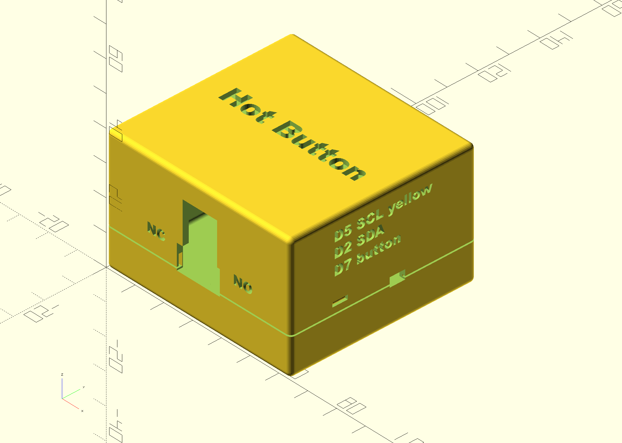
On the lid of the enclosure is just simple label "Hot Button". On one side is an opening for the USB power port and the contacts for the relay. The D1 Mini is above the relay board specifically because the relay board needs a wider opening, and it makes it easier to print without supports by using that orientation. The mini breadboard will be stuck with it's double-sided tape to the lid, under the "Hot Button" label.
I put some hints for myself in text on the enclosure so that I won't have to refer to notes when I am down in the basement fooling around with it. I know from past experience how easy it is to pull the wires out of the breadboard and needing to figure out the positions for plugging them back in. Near the opening for the relay contacts is a reminder of which side is normally open and which side is normally closed. On another side are reminders of which GPIO pins I used. I used the D1 Mini pin names because that's what I would be looking at when re-assembling things. I only needed to remind myself of the SCL and SDA pins for the I2C interface since the ground and power are obvious. Further, when the enclosure is closed, there is a reminder that the SCL line is using a yellow wire. Again, power and ground are obvious, and SDA must be whatever other wire is left over.
On the same side as those pin reminders is a small cut-out for the I2C wiring to connect the climate sensor. There's another cut-out like it on the opposite side because I haven't decided which side I will end up using.
![]()
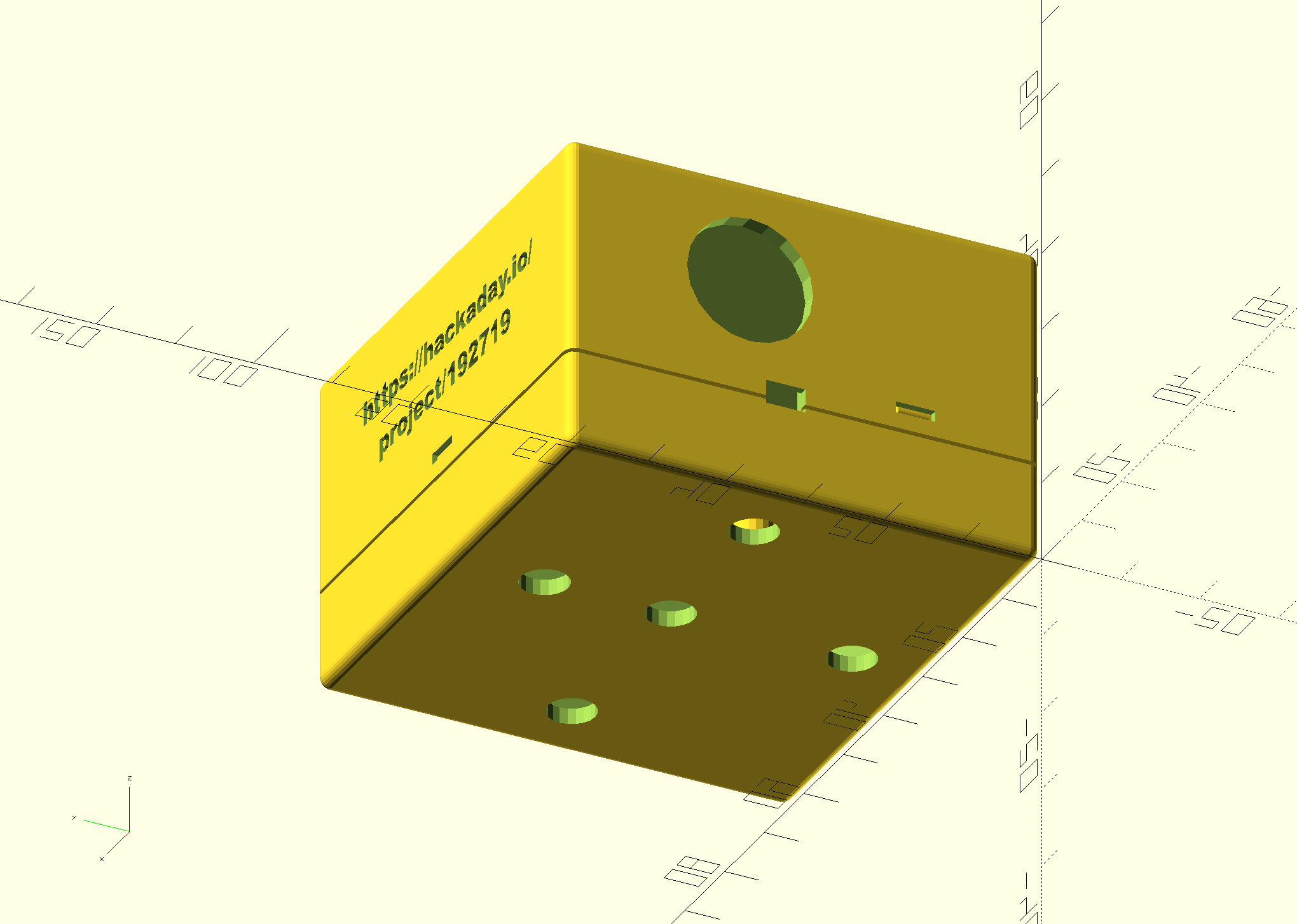
On another side is a large circular cut-out for the local button switch. The 3D printer is able to print that circle on a vertical face without needing supports. Also visible is a URL to this project. That's for the benefit of some future owner of my house who might be wondering what the heck this little box is.
![]()
I'm not yet sure how I will mount this enclosure. I might use velcro or 3M Command Strips to stick it on the side of the water heater, or I might use screws to attach it to the wall. For that latter case, I put a few holes in the bottom of the base for screws.
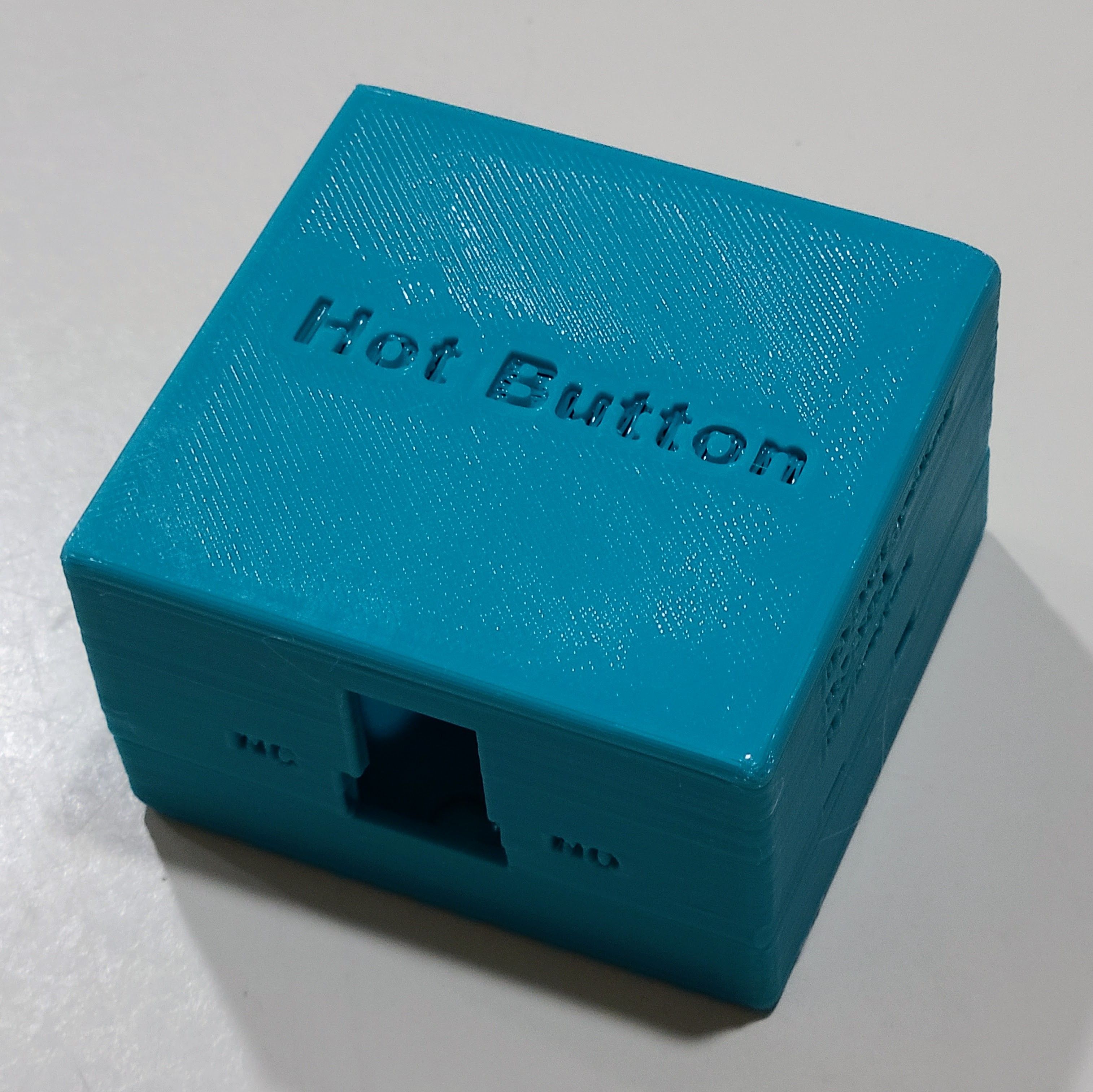
Here's the actual printed enclosure. I printed it with teal PLA+ filament with 0.28 layer thickness and 15% infill. Although PLA+ is a little bit fragile due to stiffness, I don't expect to take the thing apart very often. Since it will live in an out of the way location, it's also not worth printing it with a smaller layer height. It's more or less 60mm in length and width, and it's about 40mm tall. In addition to the padded tape on the back of the mini breadboard, I will also use some kind of thin padding inside the base so that the whole electronics assembly is held snugly inside.
![]()
Here's the OpenSCAD design file for the enclosure.
// https://hackaday.io/project/192719-calling-for-hot-water // Enclosure for D1 Mini with relay board. // Template from: //----------------------------------------------------------------------- // Yet Another Parameterized Projectbox generator // See https://mrwheel-docs.gitbook.io/yappgenerator_en/ for // documentation and a download pointer. //----------------------------------------------------------------------- // These "local" variables have to come before the "include" statement. // The "hbrb_" numbers are sort of fundamental constants of mine. hbrb_bottom_zsize = 14; hbrb_lid_zsize = 22; // Overall PCB coordinates hbrb_pcb_size_x = 60; hbrb_pcb_size_y = 56; hbrb_pcb_thickness = 2; hbrb_lid_plane_thickness = 2.0; hbrb_base_plane_thickness = 2.0; hbrb_pin_diameter = 4; hbrb_pin_offset = 7; hbrb_screwhole_diameter = 6; hbrb_screwhole_offset = 7; hbrb_ridge_height = 4; hbrb_round_radius = 1.5; hbrb_bottom_zsize_total = hbrb_bottom_zsize + hbrb_round_radius; hbrb_lid_zsize_total = hbrb_lid_zsize + hbrb_round_radius; hbrb_standoff_height = hbrb_bottom_zsize_total - hbrb_base_plane_thickness - hbrb_ridge_height; hbrb_relay_width = 15; hbrb_relay_height = 8; hbrb_relay_zbase = 0; hbrb_usb_width = 12; hbrb_usb_height = 14; hbrb_usb_zbase = hbrb_relay_height - 0.5; hbrb_i2c_width = 5; hbrb_i2c_height = 3; hbrb_i2c_zbase = 0; hbrb_button_diameter = 16; hbrb_typeface = "Arial Black:style=regular"; hbrb_text_engrave_fraction = 0.75; include printBaseShell = true; printLidShell = true; wallThickness = 2.0; basePlaneThickness = hbrb_base_plane_thickness; lidPlaneThickness = hbrb_lid_plane_thickness; // These two heights were obtained by trial and error. The cutouts on // the sides are either exactly at the seam where the base and lid // join, or the seam splits the cutouts and shares it between base and // lid. That allows you to print the whole enclosure without supports. baseWallHeight = hbrb_bottom_zsize; lidWallHeight = hbrb_lid_zsize; ridgeHeight = hbrb_ridge_height; ridgeSlack = 1.5; roundRadius = hbrb_round_radius; standoffHeight = hbrb_bottom_zsize_total - hbrb_base_plane_thickness - hbrb_ridge_height - hbrb_pcb_thickness; pinDiameter = hbrb_pin_diameter - 0.4; // avoid fitting too snugly pinHoleSlack = 0.3; standoffDiameter = pinDiameter + 1.5; pcbLength = hbrb_pcb_size_x; pcbWidth = hbrb_pcb_size_y; pcbThickness = hbrb_pcb_thickness; // We don't need padding because we're not concerned about the corners. paddingFront = 0; paddingBack = 0; paddingRight = 0; paddingLeft = 0; //-- D E B U G -----------------//-> Default --------- showSideBySide = false; //-> true onLidGap = 0; //-> 3; //shiftLid = 1; //hideLidWalls = false; //-> false //colorLid = "yellow"; //hideBaseWalls = false; //-> false //colorBase = "white"; //showOrientation = true; //showPCB = true; //showPCBmarkers = true; //showShellZero = true; //showCenterMarkers = true; //inspectX = 0; //-> 0=none (>0 from front, <0 from back) //inspectY = 0; //-> 0=none (>0 from left, <0 from right) //-- D E B U G --------------------------------------- pcbStands = [ [ hbrb_pin_offset, hbrb_pin_offset, yappBoth, yappPin] ,[pcbLength - hbrb_pin_offset, pcbWidth - hbrb_pin_offset, yappBoth, yappPin] ,[ hbrb_pin_offset, pcbWidth - hbrb_pin_offset, yappBoth, yappPin] ,[pcbLength - hbrb_pin_offset, hbrb_pin_offset, yappBoth, yappPin] ]; //left and right: parallel to X-axis //back and front: parallel to Y-axis //length is X, width is Y //-- left plane -- origin is pcb[0,0,0] // (0) = posx // (1) = posz // (2) = width // (3) = height // (4) = angle // (5) = { yappRectangle | yappCircle } // (6) = { yappCenter } cutoutsLeft = [ [pcbLength/2 - hbrb_usb_width/2+0.5, hbrb_usb_zbase, hbrb_usb_width, hbrb_usb_height, 0, yappRectangle] ,[pcbLength/2 - hbrb_relay_width/2, hbrb_relay_zbase, hbrb_relay_width, hbrb_relay_height, 0, yappRectangle] ]; //-- back plane -- origin is pcb[0,0,0] // (0) = posy // (1) = posz // (2) = width // (3) = height // (4) = angle // (5) = { yappRectangle | yappCircle } // (6) = { yappCenter } cutoutsBack = [ [pcbWidth/2, hbrb_i2c_zbase, hbrb_i2c_width, hbrb_i2c_height, 0, yappRectangle] ,[pcbWidth/2 + 7, hbrb_button_diameter/2 + 7.5, hbrb_button_diameter, 0, 0, yappCircle] ]; cutoutsFront = [ [pcbLength*(1/2), hbrb_i2c_zbase, hbrb_i2c_width, hbrb_i2c_height, 0, yappRectangle] ]; //-- base plane -- origin is pcb[0,0,0] // (0) = posx // (1) = posy // (2) = width // (3) = length // (4) = angle // (5) = { yappRectangle | yappCircle } // (6) = { yappCenter } // These aren't lined up perfectly, but it doesn't matter since they will not normally be // visible. Five holes for maximum screw mounting flexibility. cutoutsBase = [ [hbrb_screwhole_offset, pcbLength/2, hbrb_screwhole_diameter, 0, 0, yappCircle] ,[pcbLength - hbrb_screwhole_offset, pcbLength/2, hbrb_screwhole_diameter, 0, 0, yappCircle] ,[pcbWidth/2, hbrb_screwhole_offset, hbrb_screwhole_diameter, 0, 0, yappCircle] ,[pcbWidth/2, pcbLength-2*hbrb_screwhole_offset, hbrb_screwhole_diameter, 0, 0, yappCircle] ,[pcbWidth/2, pcbLength/2, hbrb_screwhole_diameter, 0, 0, yappCircle] ]; // Little tabs for holding the two halves of the case together. snapJoins = [ [pcbLength/2 , 4, yappRight] ,[pcbWidth*(1/4), 4, yappFront] ,[pcbWidth*(1/4), 4, yappBack] ]; //-- origin of labels is box [0,0,0] // (0) = posx // (1) = posy/z // (2) = orientation // (3) = depth // (4) = plane {lid | base | left | right | front | back } // (5) = font // (6) = size // (7) = "label text" // trial and error positions since no way to calculate rendered sizes in OpenSCAD, and YAPP is always left-justified labelsPlane = [ [ 8, pcbLength/2 - 2, 0, lidPlaneThickness * hbrb_text_engrave_fraction, "lid", hbrb_typeface, 6, "Hot Button" ] ,[14, roundRadius+16, 0, lidPlaneThickness * hbrb_text_engrave_fraction, "left", hbrb_typeface, 3, "NC" ] ,[44, roundRadius+16, 0, lidPlaneThickness * hbrb_text_engrave_fraction, "left", hbrb_typeface, 3, "NO" ] ,[14, hbrb_bottom_zsize+hbrb_lid_zsize - 4, 0, lidPlaneThickness * hbrb_text_engrave_fraction, "front", hbrb_typeface, 3, "D5 SCL yellow" ] ,[14, hbrb_bottom_zsize+hbrb_lid_zsize - 8, 0, lidPlaneThickness * hbrb_text_engrave_fraction, "front", hbrb_typeface, 3, "D2 SDA" ] ,[14, hbrb_bottom_zsize+hbrb_lid_zsize -13, 0, lidPlaneThickness * hbrb_text_engrave_fraction, "front", hbrb_typeface, 3, "D7 button" ] ,[12, roundRadius+26, 0, lidPlaneThickness * hbrb_text_engrave_fraction, "right", hbrb_typeface, 3, "https://hackaday.io/" ] ,[16, roundRadius+20, 0, lidPlaneThickness * hbrb_text_engrave_fraction, "right", hbrb_typeface, 3, "project/192719" ] // if you are changing things and lose track of which side is which, you can uncomment these temporarily //, [ 8, 5, 0, 1, "left", hbrb_typeface, 7, "L" ] //, [40, 5, 0, 1, "front", hbrb_typeface, 7, "F" ] //, [5, 5, 0, 1, "back", hbrb_typeface, 7, "B" ] ]; //---- This is where the magic happens ---- YAPPgenerate(); -
A short video demo
09/10/2023 at 23:58 • 0 commentsThis video shows the D1 Mini with the relay board beside an M5Stack Atom Lite device. You can see two complete cycles of the transitions described in earlier project logs. Obviously, you can't see the Home Assistant server controlling things, but you can see how responsive things are. The USB cables are just providing power. All communications are over wifi.
You may have to look kind of carefully to see the LED on the relay board flashing and the LED on the D1 Mini staying on. For test purposes, I made the timer for the pump only 15 seconds.
-
Home Assistant in the middle
09/10/2023 at 21:03 • 0 commentsHaving great frameworks like Home Assistant and ESPHome makes it simple to do simple things. It's like many other IRL infrastructure things that act as multipliers for add-on projects. There are lots of ways to accomplish this in those frameworks, and I'm using mechanisms that make the most sense to me.
For this project, I've chosen to make Home Assistant automation the centerpiece tying things together. The overall flow looks like this:
- Someone presses one of the buttons.
- Home Assistant detects that button press as a trigger for an automation.
- Home Assistant "presses the button" that momentarily activates the relay.
- Home Assistant turns on the LED on the D1 Mini.
- The water heater starts the recirculation pump.
- Home Assistant calls the "set_led_hot" service on each Atom device.
- A timed delay happens.
- Home Assistant turns off the LED on the D1 Mini.
- Home Assistant calls the "set_led_cold" service on each Atom device.
The timed delay isn't the greatest situation. It means that Home Assistant has to know the timer configuration for the recirculation pump on the water heater. I'm hoping to eventually figure out a way of detecting if the pump is actually running and use that instead of a timer. I have plenty of spare GPIOs on the D1 Mini to use for that.
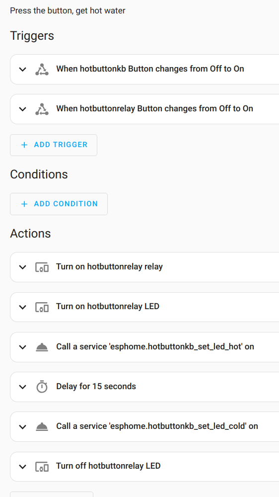
I've only got one Atom configured right now. Additional devices will be added to the triggers, along with the button on the D1 Mini. Here's what the automation looks like (the timeout is temporarily set to 15 seconds for testing purposes):
alias: Tankless hot button
description: Press the button, get hot water
trigger:
  - platform: state
    entity_id:
      - binary_sensor.hotbuttonkb_button
    from: "off"
    to: "on"
  - platform: state
    entity_id:
      - binary_sensor.hotbuttonrelay_button
    from: "off"
    to: "on"
condition: []
action:
  - type: turn_on
    device_id: 631ea0d418d7508fdbf35e046f077906
    entity_id: 556da559467ce707e6dd9f6c5ad39797
    domain: switch
  - type: turn_on
    device_id: 631ea0d418d7508fdbf35e046f077906
    entity_id: 2a370e76eeb5971f48e70e2f75f500e7
    domain: switch
  - service: esphome.hotbuttonkb_set_led_hot
    data: {}
  - delay:
      hours: 0
      minutes: 0
      seconds: 15
      milliseconds: 0
  - service: esphome.hotbuttonkb_set_led_cold
    data: {}
  - type: turn_off
    device_id: 631ea0d418d7508fdbf35e046f077906
    entity_id: 2a370e76eeb5971f48e70e2f75f500e7
    domain: switch
mode: restart
The device and entity IDs in the YAML make it a little tricky to see what's going on, so here is a GUI screenshot of the same automation:
![]()
-
The buttons that you press
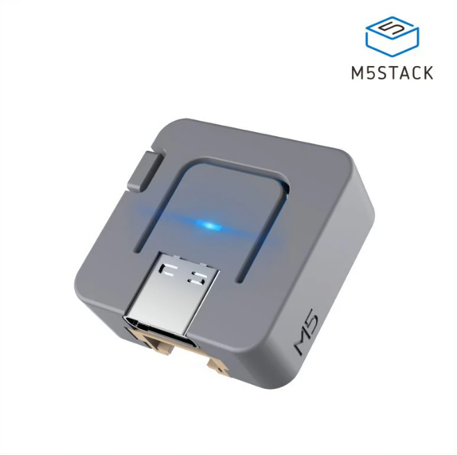
09/10/2023 at 20:28 • 0 commentsI had good experience with using the M5Stack Atom Matrix devices in my Water Watcher project. With a 5x5 grid of RGB LEDs, there are lots of possibilities for displaying feedback, and the entire face of the device is a large button that can be pushed to signal something. For this project, I still need a pushable button, but I only need a couple bits of feedback: has the button been pushed, and is the recirculation pump still active. I decided to use M5Stack Atom Lite devices for this project. They are much more compact than anything I would likely create myself. They have an ESP32 and are powered via USB-C. They have a large button on the face and a single RGB LED. They have several other features that I don't need for this project.
![]()
I expect to deploy at least two of these in upstairs bathrooms, and it's possible I will sprinkle one or two more at other locations. I wanted all of the feedback to go to all of the devices, and I also wanted to know reliably that the button press had the desired effect. For those reasons, the button press is detected by Home Assistant, and Home Assistant controls the RGB LED.
The button press is simple to configure in ESPHome and is readily detected as a trigger by Home Assistant. The RGB LED control takes a little bit more work. I defined three services on the Atom: set_led_hot, set_led_cold, and set_led_off. That abstracts the device behavior from Home Assistant's intentions when it calls the services. Each service just calls a script to do something with the RGB LED. The Atom boots up as "cold" and is typically in that state. The RGB LED emits a soft and steady blue. The "hot" display is orange-yellow and blinking. The "off" display is obvious, though I don't currently have a use for it. All of the colors, brightness values, and blinking behavior were set by trial and error to get something I liked.
I split the ESPHome configuration into two pieces. One piece has the device-specific information (node name and API encryption key), and the ESPHome "include" feature is used to combine that with a common file that is the same for all of the devices.
One of the device-specific pieces:
substitutions:
  node_name: hotbuttonkb
  api_key: !secret hotbuttonkb_apikey

<<: !include { file: hotbutton.yaml.inc}
The common file:
esphome: name: $node_name on_boot: then: # delay to allow other boot time stuff to settle down - delay: 5s - script.execute: set_led_cold esp32: board: pico32 wifi: networks: - ssid: !secret wifi_ssid password: !secret wifi_password sensor: - platform: wifi_signal name: ${node_name} WiFi Signal logger: level: DEBUG ota: password: !secret ota_password api: encryption: key: ${api_key} reboot_timeout: 60min services: - service: set_led_hot then: - logger.log: tag: 'hotbutton' level: INFO format: "service: set_led_hot" - script.execute: set_led_hot - service: set_led_cold then: - logger.log: tag: 'hotbutton' level: INFO format: "service: set_led_cold" - script.execute: set_led_cold - service: set_led_off then: - logger.log: tag: 'hotbutton' level: INFO format: "service: set_led_off" - script.execute: set_led_off binary_sensor: - platform: gpio pin: number: GPIO39 inverted: true name: ${node_name} Button id: big_button internal: false light: - platform: fastled_clockless id: bright_light name: ${node_name} LED chipset: SK6812 pin: GPIO27 num_leds: 1 rgb_order: GRB # required default_transition_length: 0s effects: - pulse: name: fast_pulse transition_length: 0.25s update_interval: 0.25s min_brightness: 20% max_brightness: 99% script: - id: set_led_hot then: - light.turn_on: id: bright_light red: 100% green: 60% blue: 0% effect: fast_pulse - id: set_led_cold then: - light.turn_on: id: bright_light color_brightness: 20% red: 0% green: 0% blue: 100% effect: none - id: set_led_off then: - light.turn_on: id: bright_light color_brightness: 0% red: 0% green: 0% blue: 0% effect: none -
Relay control software
09/10/2023 at 03:41 • 0 commentsIt's child's play to use ESPHome to configure the D1 Mini to operate the companion relay.
switch:
  - platform: gpio
    id: i_relay
    name: '${node_name} relay'
    pin: '${RELAY}'
    restore_mode: ALWAYS_OFF
    icon: mdi:hot-tub
    on_turn_on:
      - delay: 500ms
      - switch.turn_off: i_relay
This switch can be directly controlled by Home Assistant. When something turns the switch on, it waits 500 milliseconds and then turns itself off. I had the switch turn the relay off automatically to isolate that information to the D1 Mini. There's no need for any outside entity to know the implementation detail of how we're simulating a human button press.
The relay board has a red LED that lights while the relay is activated, but that only lasts for a fraction of a second. The D1 Mini on-board blue LED wasn't being used for anything, so I exposed it so that Home Assistant can turn it on and off. The idea is that pushing the button is momentary, but the recirculation pump then runs for some number of minutes. Home Assistant will turn on the on-board LED for the duration of the pump activity. Both LEDs will be somewhat visible through the enclosure without needing their own openings.
My previous water watcher project included a BME280 climate sensor as part of my sprinkling of climate sensors around my house. I configured 2 pins of the D1 Mini as I2C so I can do the same thing here. The sensor will dangle out the side of the enclosure on a few dupont jumper wires. (I might later change that to a BME688 sensor, which can also detect various types of gases, but that's still I2C.)
In addition to the remote controls that I'll describe in a later project log, I also wanted to have a physical button to activate things. That's mainly for testing purposes while I'm fiddling with things. This is not the same thing as the simple sort of button that can be used directly with the Navien unit. Instead, it will follow the entire path of handoffs, just like the remote buttons. Even though it originates on the D1 Mini with the relay, it doesn't directly activate the relay. It's detected as a GPIO binary sensor by both ESPHome and Home Assistant.
Although this is a work in progress, here's what the ESPHome configuration for the D1 Mini looks like today. Notice that a few values come via the ESPHome "!secret" mechanism.
# https://hackaday.io/project/192719-calling-for-hot-water

substitutions:
  node_name: hotbuttonrelay
  RELAY:  'D1'
  SCL:    'D5'
  SDA:    'D2'
  LED:    'D4'
  BUTTON: 'D7'
  log_level: 'DEBUG'

esphome:
  name: ${node_name}
  platform: ESP8266
  board: d1_mini

wifi:
  ssid:      !secret wifi_ssid
  id:        !secret wifi_ssid
  password:  !secret wifi_password
  power_save_mode: high
  fast_connect: on
  manual_ip:
    static_ip: !secret hotbuttonrelay_ip
    gateway:   !secret wifi_gateway
    subnet:    !secret wifi_subnet
    dns1:      !secret wifi_dns1
    dns2:      !secret wifi_dns2

logger:
   level: ${log_level}
api:
  encryption:
    key: !secret hotbuttonrelay_apikey
  reboot_timeout: 60min
ota:
  password: !secret ota_password

switch:
  - platform: restart
    name: "${node_name} Reboot"

  - platform: gpio
    id: i_relay
    name: '${node_name} relay'
    pin: '${RELAY}'
    restore_mode: ALWAYS_OFF
    icon: mdi:hot-tub
    on_turn_on:
      - delay: 500ms
      - switch.turn_off: i_relay

  - platform: gpio
    id: i_led
    name: '${node_name} LED'
    pin: '${LED}'
    inverted: true
    restore_mode: ALWAYS_OFF
    icon: mdi:led-on

# Local test button. This goes through the relay logic, so it's not an analog press of the water heater button.
binary_sensor:
  - platform: gpio
    name: "${node_name} Button"
    id: i_button
    pin:
      number: '${BUTTON}'
      inverted: true
      mode:
        input: true
        pullup: true
    filters:
      - delayed_on: 10ms
      - delayed_off: 10ms

i2c:
  sda: ${SDA}
  scl: ${SCL}
  scan: false
  id: i_i2c

sensor:
  - platform: bme280
    id: i_bme280
    address: 0x76
    update_interval: 60s
    temperature:
      name: "${node_name} Temp"
      device_class: "temperature"
      oversampling: 16x
    pressure:
      name: "${node_name} AirPr"
      device_class: "pressure"
      oversampling: 16x
    humidity:
      name: "${node_name} RHumidity"
      device_class: "humidity"
      oversampling: 16x


# From the Arduino board definitions file
# #define PIN_WIRE_SDA (4)
# #define PIN_WIRE_SCL (5)

# static const uint8_t SDA = PIN_WIRE_SDA;
# static const uint8_t SCL = PIN_WIRE_SCL;

# #define LED_BUILTIN 2

# static const uint8_t D0   = 16;
# static const uint8_t D1   = 5;
# static const uint8_t D2   = 4;
# static const uint8_t D3   = 0;
# static const uint8_t D4   = 2;
# static const uint8_t D5   = 14;
# static const uint8_t D6   = 12;
# static const uint8_t D7   = 13;
# static const uint8_t D8   = 15;
# static const uint8_t RX   = 3;
# static const uint8_t TX   = 1;
The D1 Mini was first produced a long time ago, and the pin labels reflect the Arduino style. That's very handy if you are using the Arduino IDE, but I am not. ESPHome can use the Arduino designations for a lot of things, but it confuses my tiny brain. It's harder than I expected to find the Espressif GPIO numbering of the pins. I finally found it by working my way through the Arduino IDE board definition files.
Calling for hot water
Remote controlled buttons for activating hot water recirculation.