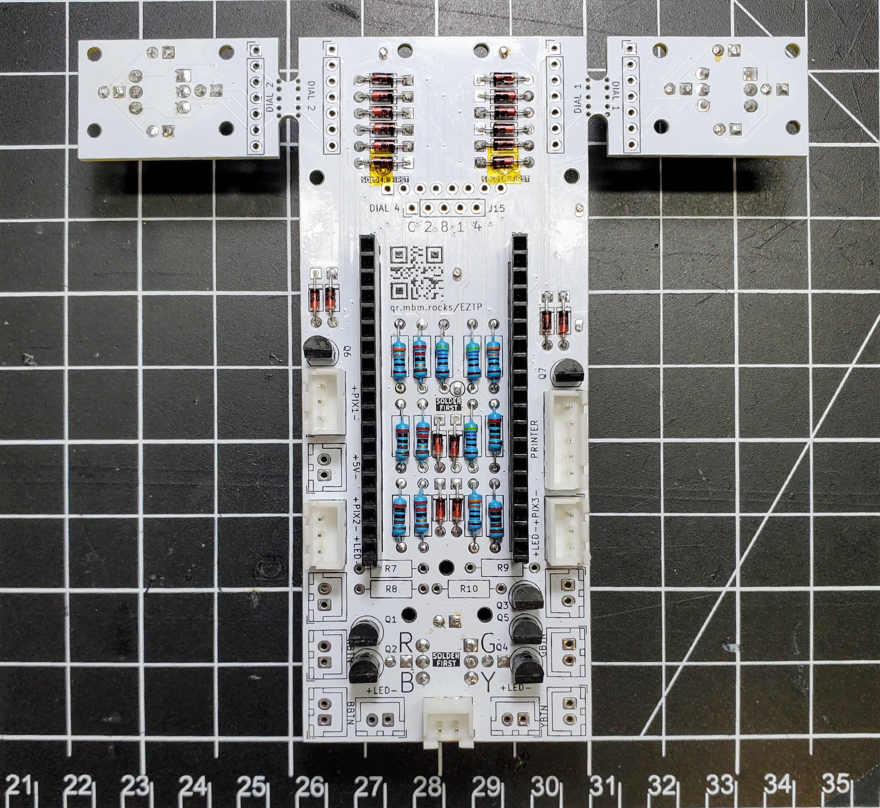
The PCBs arrived and everything went together smoothly.

The dials had to be installed first because the top/bottom LEDs were slightly too close to the switch body and wouldn't let the dials sit flush with the pcb when installed first.

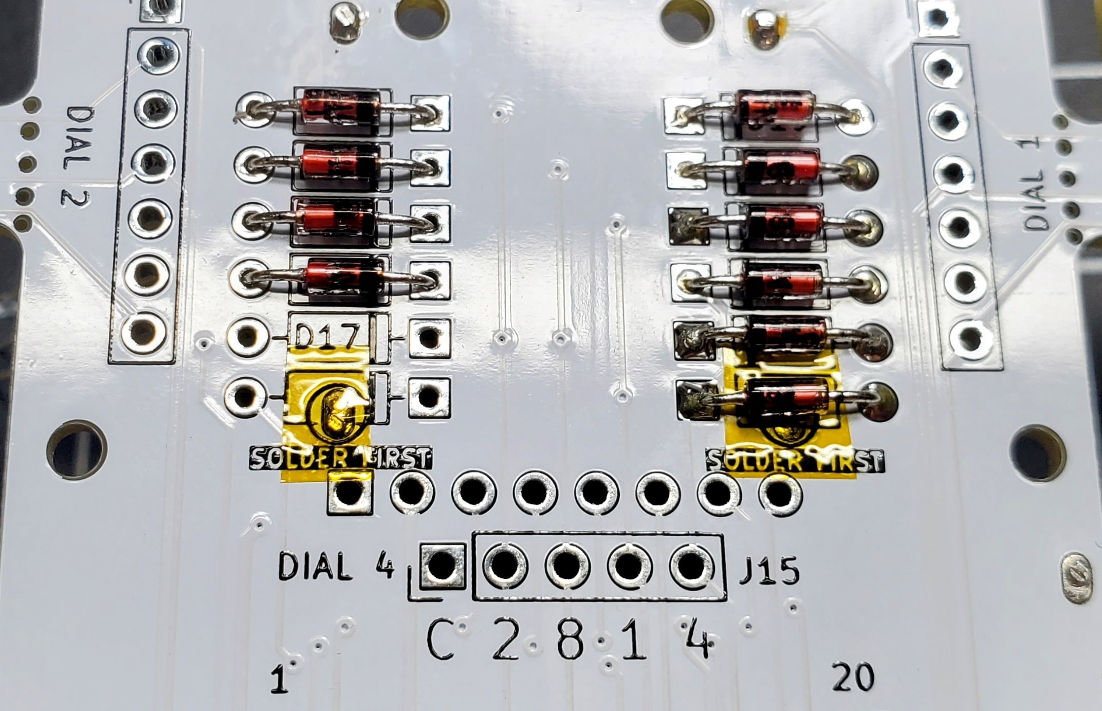
The Magnetic Reed switches have a solder joint under two diodes and needed to be installed before the diodes. I covered the joints with Kapton tape even though the diode body shouldn't be conductive.

After the reed switches were installed, I added the resistors, transistors, and microcontroller socket.

I clamped the PCB to the table to make sure the cable plugs were completely flat. I only installed sockets for connections going to things mounted to the body. The buttons and LEDs attached to the face plate will be wired directly to the board.
 Jon
Jon
Discussions
Become a Hackaday.io Member
Create an account to leave a comment. Already have an account? Log In.