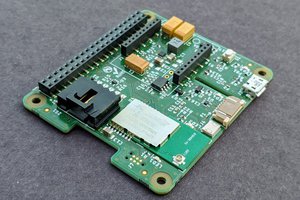
The thermocouple voltage is measured, and cold junction compensation is performed by the MAX 31856 (U2) which communicates with the host via SPI. The individual thermocouples are multiplexed via dual 8 way switches ADG1607 (U3,U4,U5 & U6) giving a total capacity of 32 channels. The analog switches are addressed and controlled via the output of I2C PIO PCF8574 (U7). D0, 1 & 2 set the multiplexer channel. D3,4,5 & 6 select the individual multiplexers. D7 drives a status LE
The default address for the I2C (PCF8574) device is 0. This can be changed by cutting the PCB links marked board address and soldering a paste link high to set an address other than 0. Using the I2C and TC expansion ports, more boards can be stacked on top of each other, up to 8 in total. You could build another 8 boards using PCF8574A devices which have a different I2C address, giving a potential capacity of 512 channels!
Setting up the Raspberry Pi
Hardware Setup
- Plug in your Raspberry Pi with an attached keyboard, mouse and monitor.
- Boot your Pi and log in.
- Update your Pi to the latest configuration with the following two commands:
- sudo apt-get update
- sudo apt-get upgrade
- Reboot the Raspberry Pi
- Switch on the required hardware used to run the Expandable Thermocouple Board. Generally this is to enable the communications paths I2C and SPI. Both are used to run the board. Also enable SSH, so you can remotely connect to the Raspberry Pi across your network. You do this by running the utility sudo raspi-config
- In the Interface section enable, I2C, SPI and SSH.
- You can now reboot and should be able to remotely connect to the Pi using SSH.
Software Setup
- The Python language should be installed in a standard installation.
- Download the software package from the link below.
- Decompress the file with the command shown.
- tar -xf XXXXXX
- In Progress
 piplay

 Rob Crouthamel
 akanzler007
 foamyguy
There is no cold juntion compensation near or under the scew terminals.