 microwavemont
I know lots of hackaday readers are HDL specialist and this content may not be useful, but beginner (including me) needs some struggle just for simple application. Here I would introduce "how to make simple counter" using my training board.
The training board contains 32.768 kHz crystal oscillator and the frequency is very low , compared to general 8-pin DIP crystal oscillator but for making "count-up every second" requires still 15bit (32768 divider) to this frequency. Also 7-seg LED utilisation needs binary to display recorder. In the case of hardware logic (or combination of 74 series), we need to prepare specific ICs, but in the case of HDL, we just need to write how it works.
module counter(
    input CLK,RST,
	 output reg [6:0] nSEG,//seven segment output
	 output		[2:0] nSET//activation digit output
    );


	assign nSET=4'b111;//all of LEDs are activated
	reg [17:0] cnt;// 18bit counter bit, 2^18=262144
	reg [3:0] nNumber;// seven segment decoder input(4-bit)

	always @( posedge CLK ) begin// exexcute at clock rise up
	if(RST)
	cnt<=18'b0;//counter reset if RST(P39) press
   else
	cnt <= cnt +1'b1;	// add one to counter
	nNumber <= (cnt>>14);//prepare top 4bits for 7-seg decorder
	end


	always @* begin //7-seg part

case( nNumber )//seven segment decorder
	4'h0: nSEG = 7'b0111111;//0
	4'h1: nSEG = 7'b0000110;//1
	4'h2: nSEG = 7'b1011011;//2
	4'h3: nSEG = 7'b1001111;//3
	4'h4: nSEG = 7'b1100110;//4
	4'h5: nSEG = 7'b1101101;//5
	4'h6: nSEG = 7'b1111101;//6
	4'h7: nSEG = 7'b0100111;//7
	4'h8: nSEG = 7'b1111111;//8
	4'h9: nSEG = 7'b1101111;//9
	4'ha: nSEG = 7'b1110111;//A
	4'hb: nSEG = 7'b1111100;//b
	4'hc: nSEG = 7'b0111001;//C
	4'hd: nSEG = 7'b1011110;//d
	4'he: nSEG = 7'b1111001;//E
	4'hf: nSEG = 7'b1110001;//F
	default:nSEG=7'bxxxxxxx;
	endcase
	end
endmodule
The source above is not "ultimate" nor "perfect" one but it describes counter and 7-segment decoder. As we know, in addition to verilog source, .ucf file defines the hardware connection is required as below.
NET "nSEG<0>" LOC="P2";
NET "nSEG<1>" LOC="P3";
NET "nSEG<2>" LOC="P5";
NET "nSEG<3>" LOC="P6";
NET "nSEG<4>" LOC="P7";
NET "nSEG<5>" LOC="P8";
NET "nSEG<6>" LOC="P12";

NET "nSET<0>" LOC="P40";//activation digit of second 7-seg LED
NET "nSET<1>" LOC="P41";//activation digit of first 7-seg LED
NET "nSET<2>" LOC="P42";//activation digit of seven LEDs

NET "RST" LOC="P39";


NET CLK	LOC="P1";
NET CLK TNM_NET=CLK;
TIMESPEC TS_CLK = PERIOD ck 8000 kHz;
The "P1" is connected to clock generator in my training board, and we need to write some special notation clearly indicate P1 is clock input. The rest are the same as my previous sample.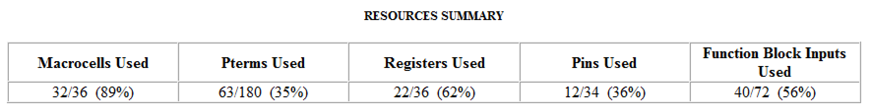
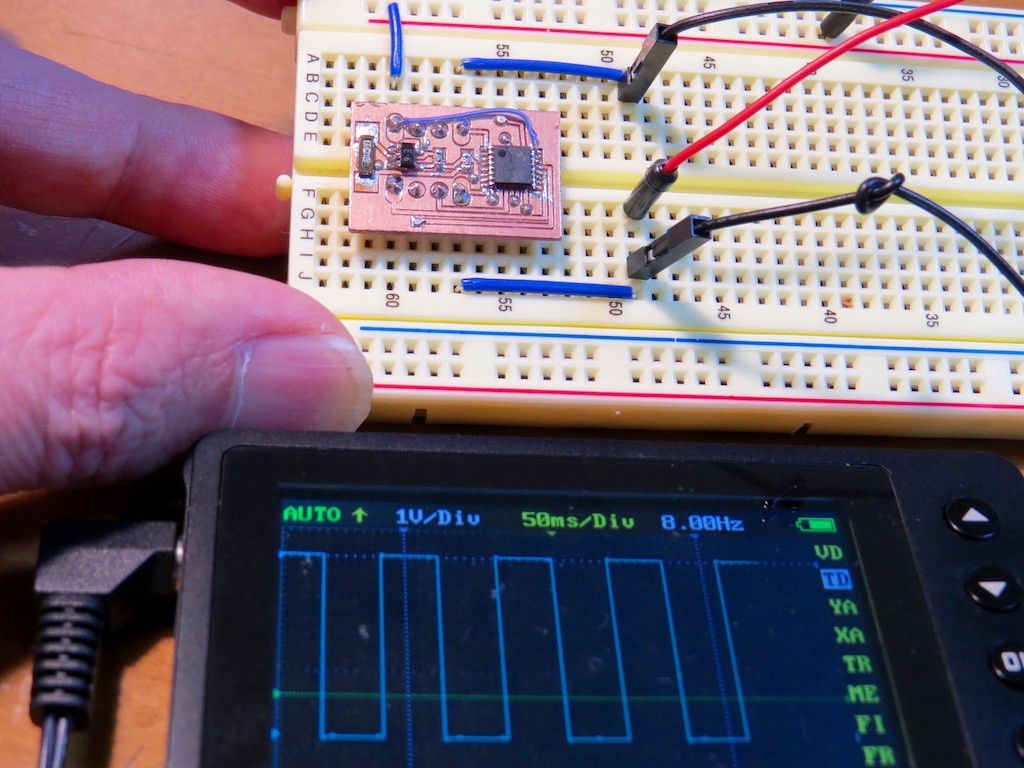
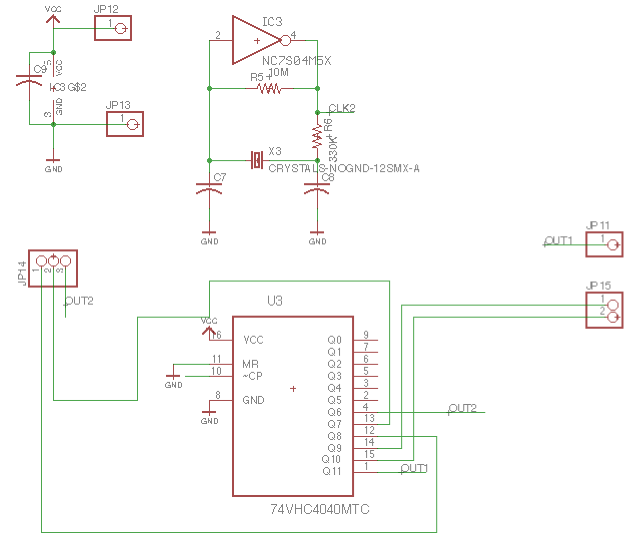
The circuit is very simple one. Of course we can make clock "around 8 Hz" by 555 or RC oscillator but the timing is not accurate at all. Here the frequency is stabilised by crystal resonator and we can make "kitchen timer" not make your Mom angry by burning cake by unreliable clock. Not only 8 Hz, it has ..
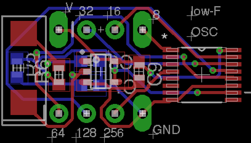
This modules has 16 to 256 Hz output. By using "8-Hz" clock timing, verilog source can be modified as,
assign nSET=4'b111;//all of LEDs are activated
reg [7:0] cnt;// 8-bit counter bit, 2^=256
reg [3:0] nNumber;// seven segment decoder input(4-bit)
always @( posedge CLK ) begin// exexcute at clock rise up
if(RST)
cnt<=8'b0;//counter reset if RST(P39) press
else
cnt <= cnt +1'b1; // add one to counter
nNumber <= (cnt>>4);//prepare top 4bits for 7-seg decorder
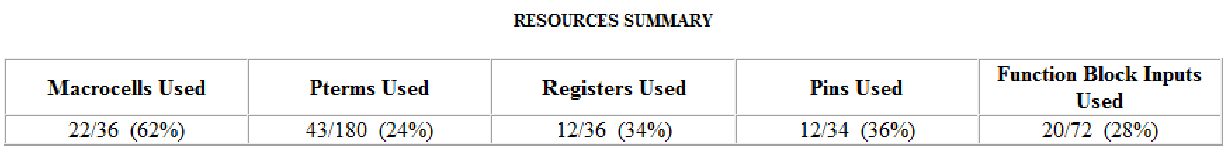
endThis modification leads to smaller usage of macro-cells, as
module counter(
    input CLK,RST,
	 output reg [6:0] nSEG,//seven segment output
	 output		[2:0] nSET//activation digit output
    );


	assign nSET=4'b111;//all of LEDs are activated
	reg [7:0] cnt;// 8-bit counter bit, 2^=256
	reg [3:0] nNumber;// seven segment decoder input(4-bit)

	always @( posedge CLK ) begin// exexcute at clock rise up
	if(RST)
	cnt<=8'b0;//counter reset if RST(P39) press
   else
	cnt <= cnt +1'b1;	// add one to counter
	nSEG <= (cnt>>4);//prepare top 4bits for 7-seg decorder
	end


/////comment out all of 7-seg decoder part//////
//	always @* begin //7-seg part
//
//case( nNumber )//seven segment decorder
//	4'h0: nSEG = 7'b0111111;//0
//	4'h1: nSEG = 7'b0000110;//1
This modification (7-seg recorder is not activated, just count-up) leads to....

YES, now down to 50%. We still have 50 % of design freedom!
Discussions
Become a Hackaday.io Member
Create an account to leave a comment. Already have an account? Log In.