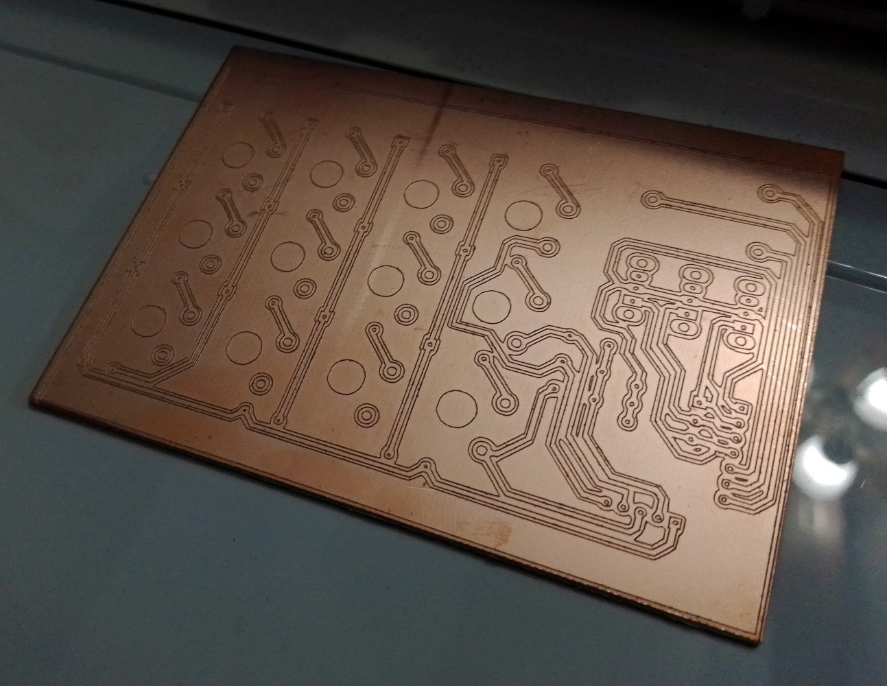
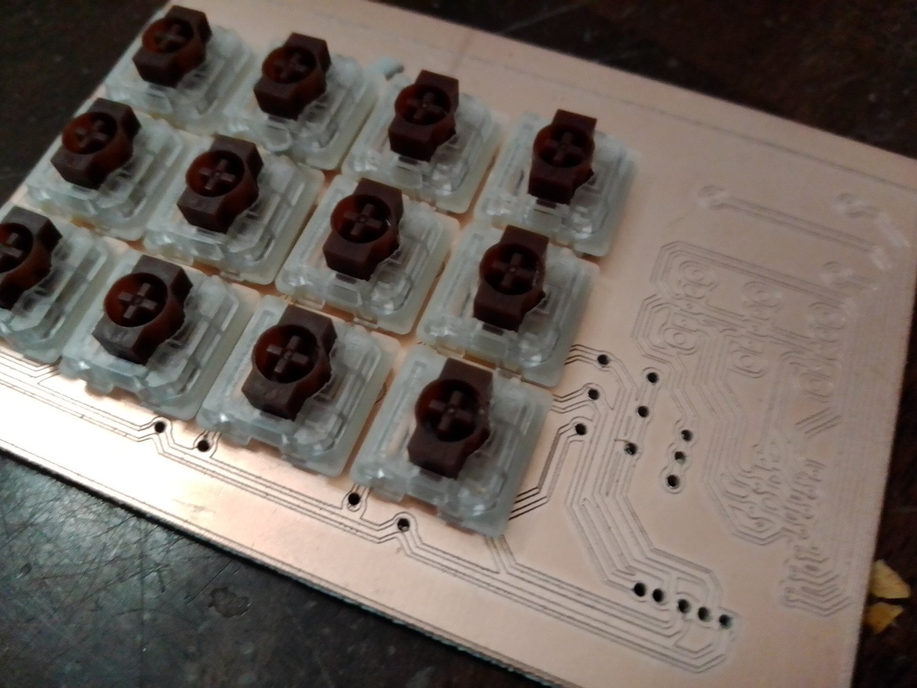
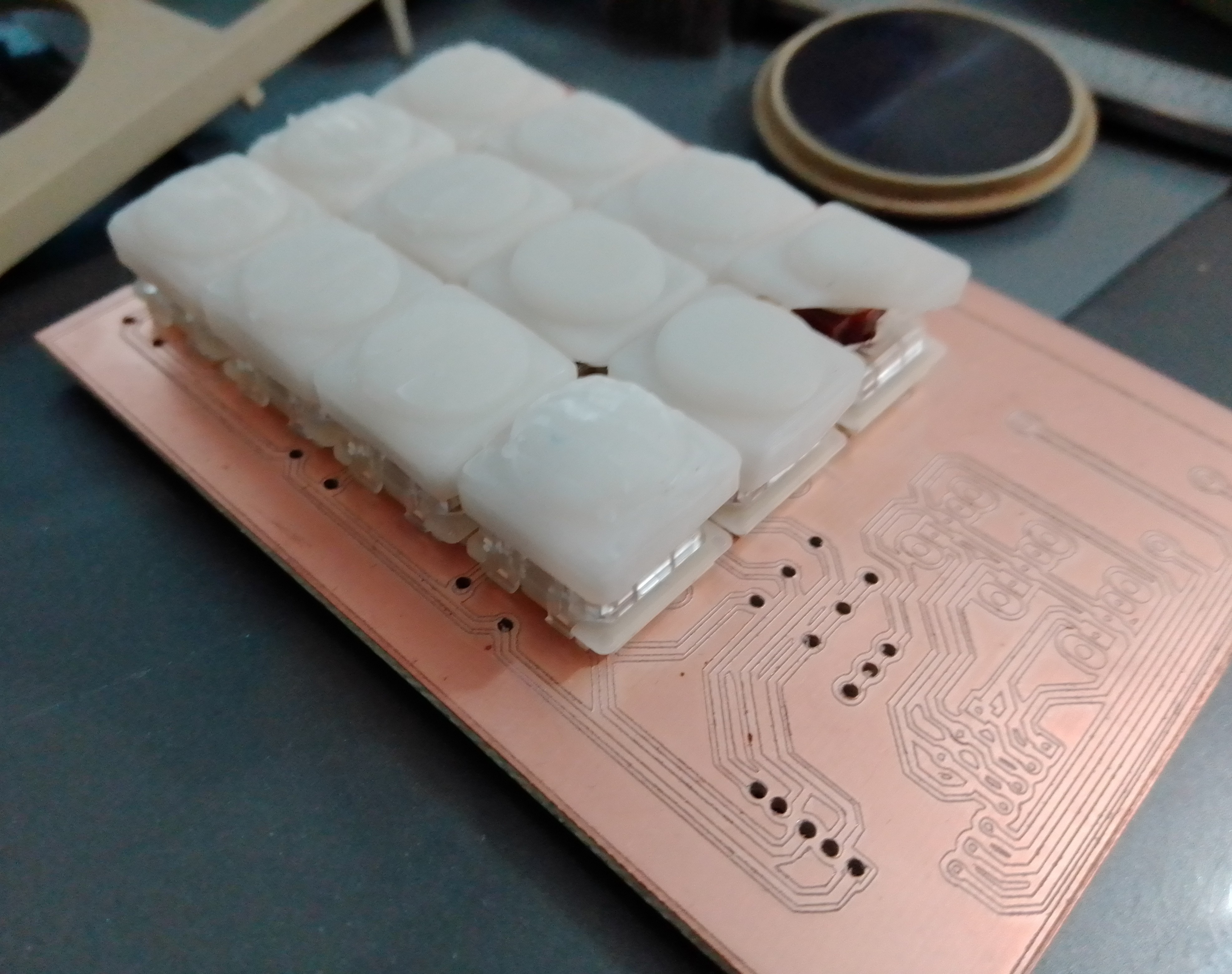
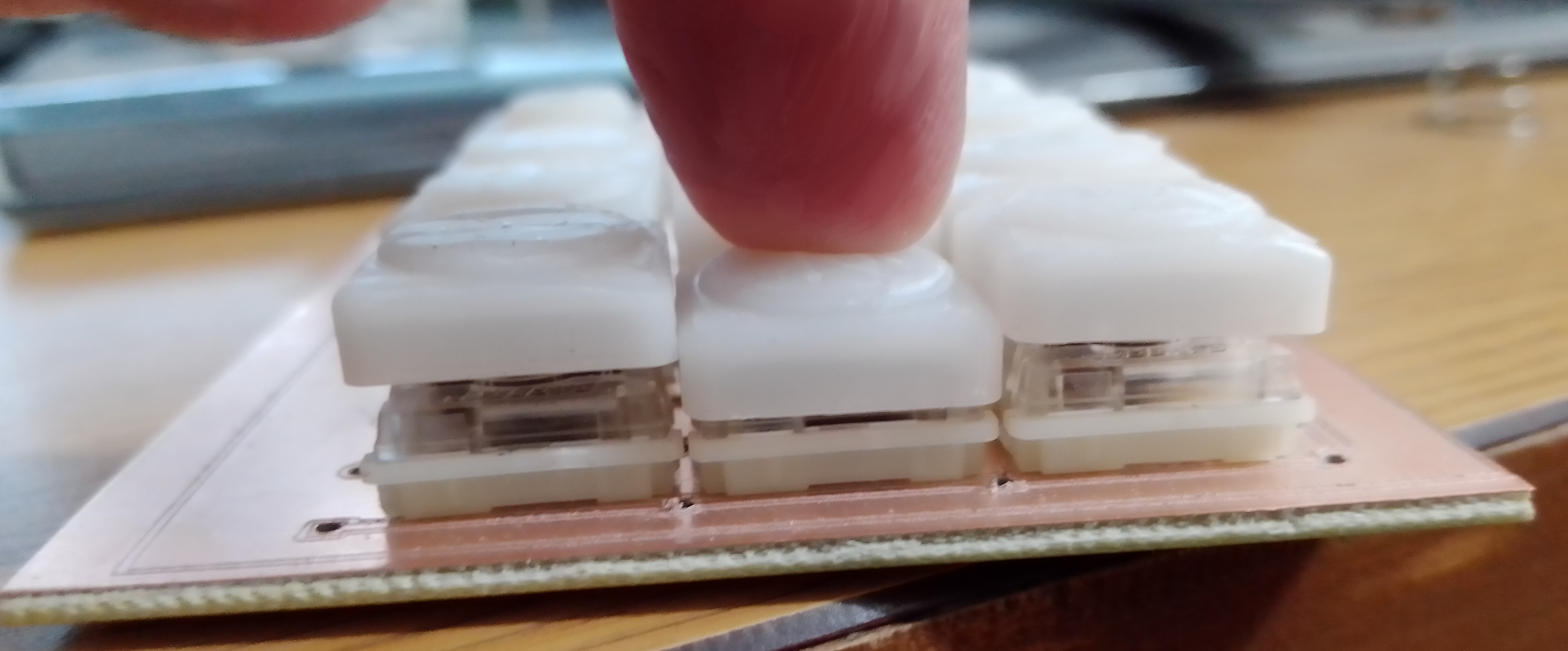
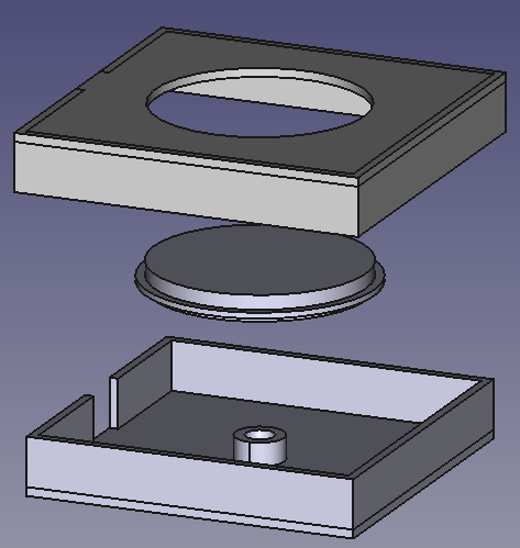
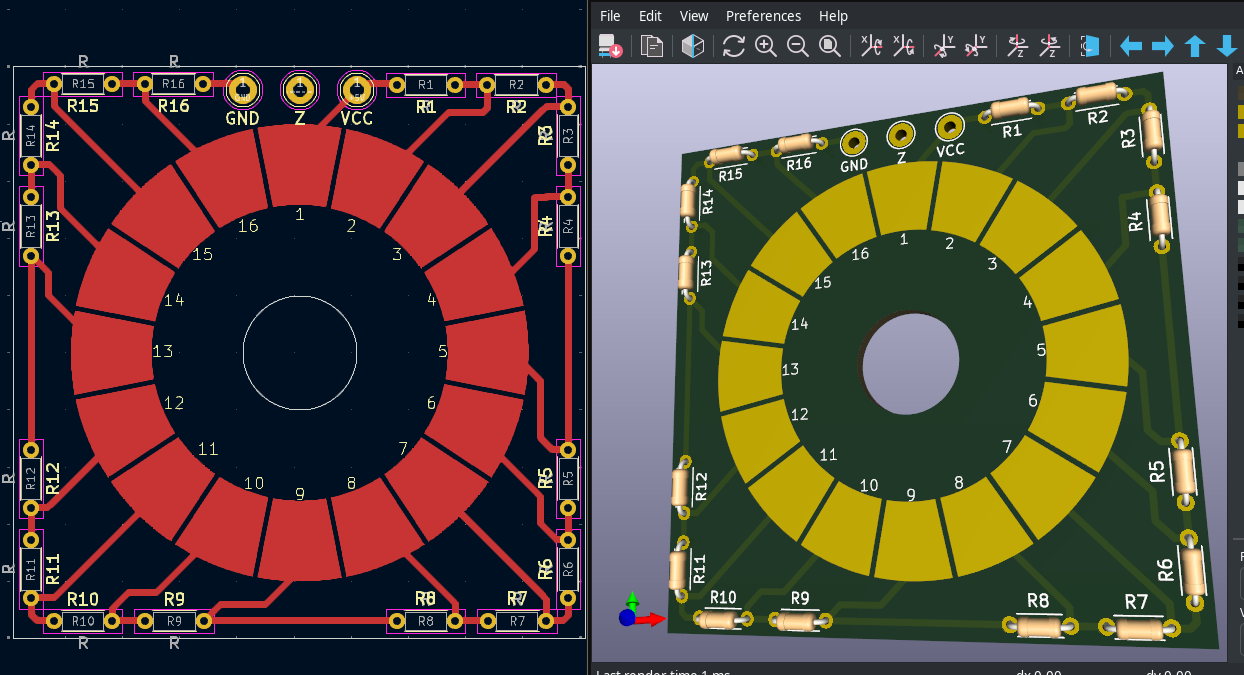
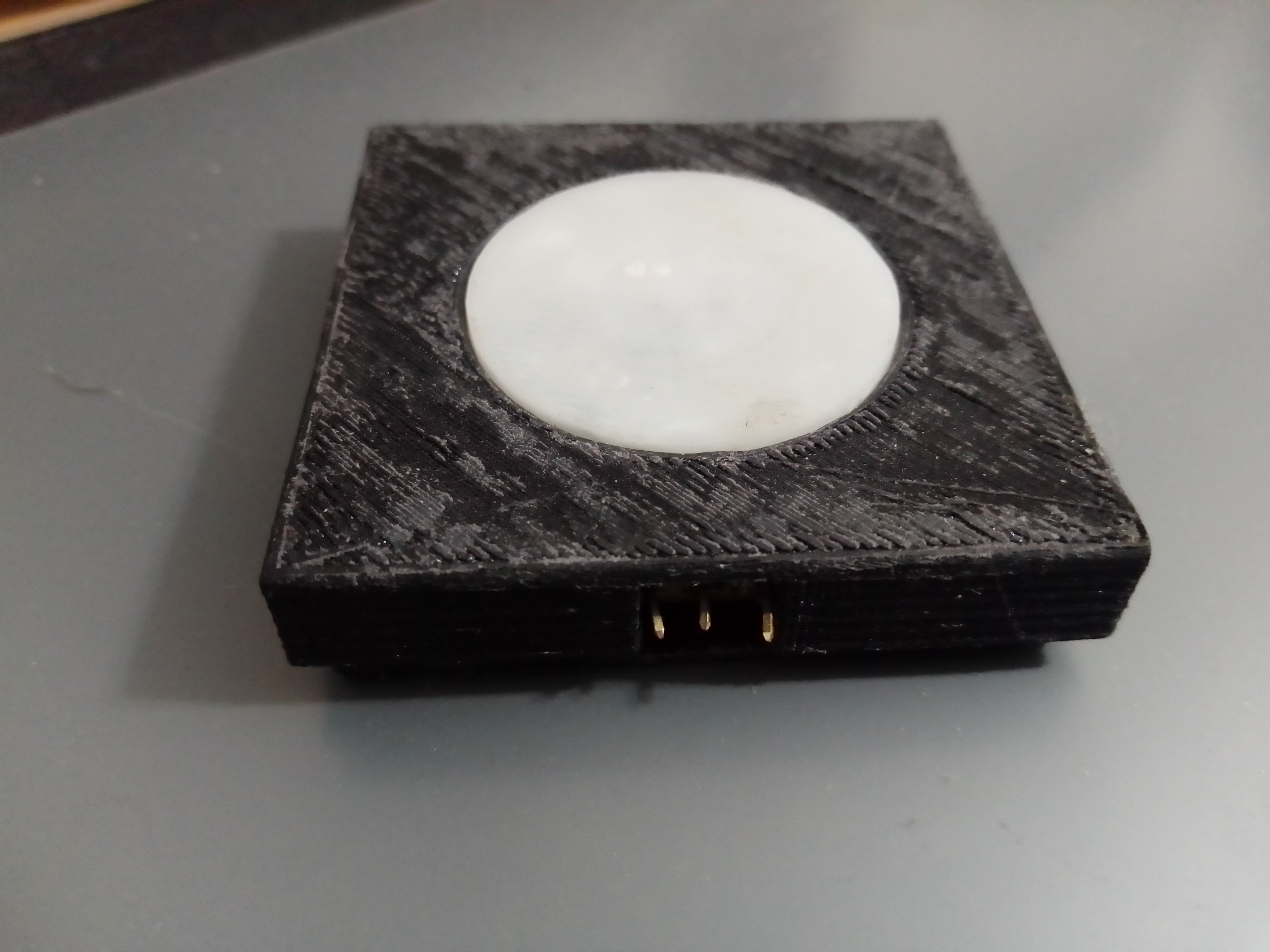
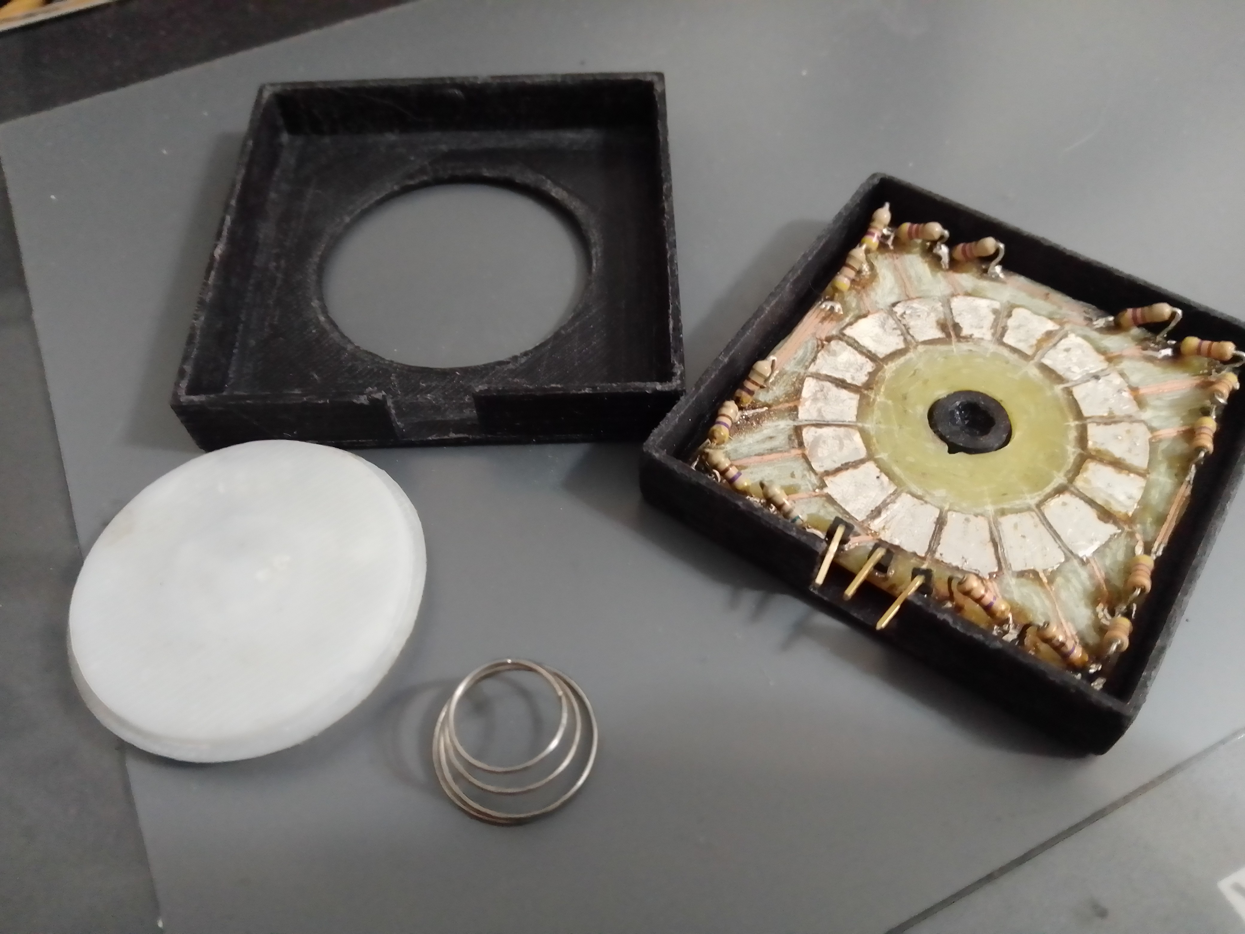
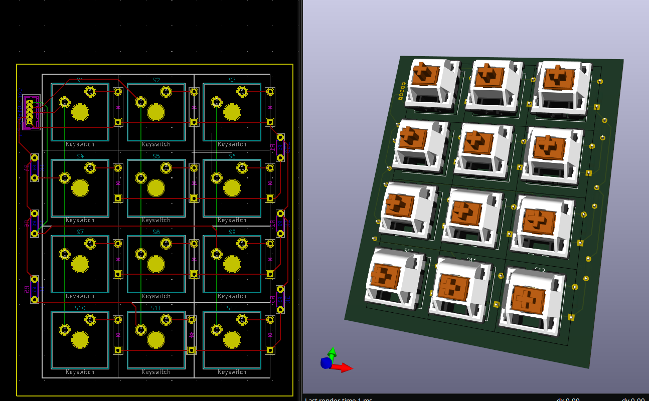
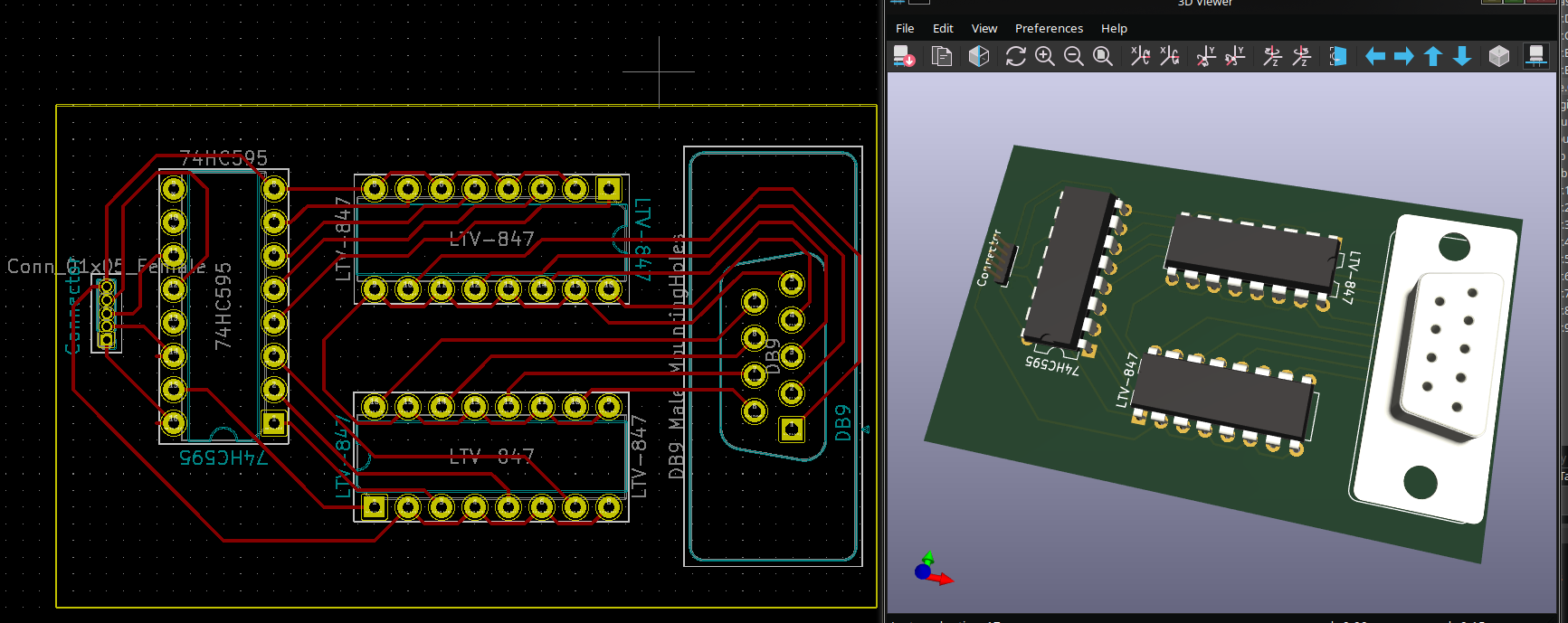
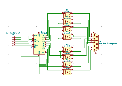
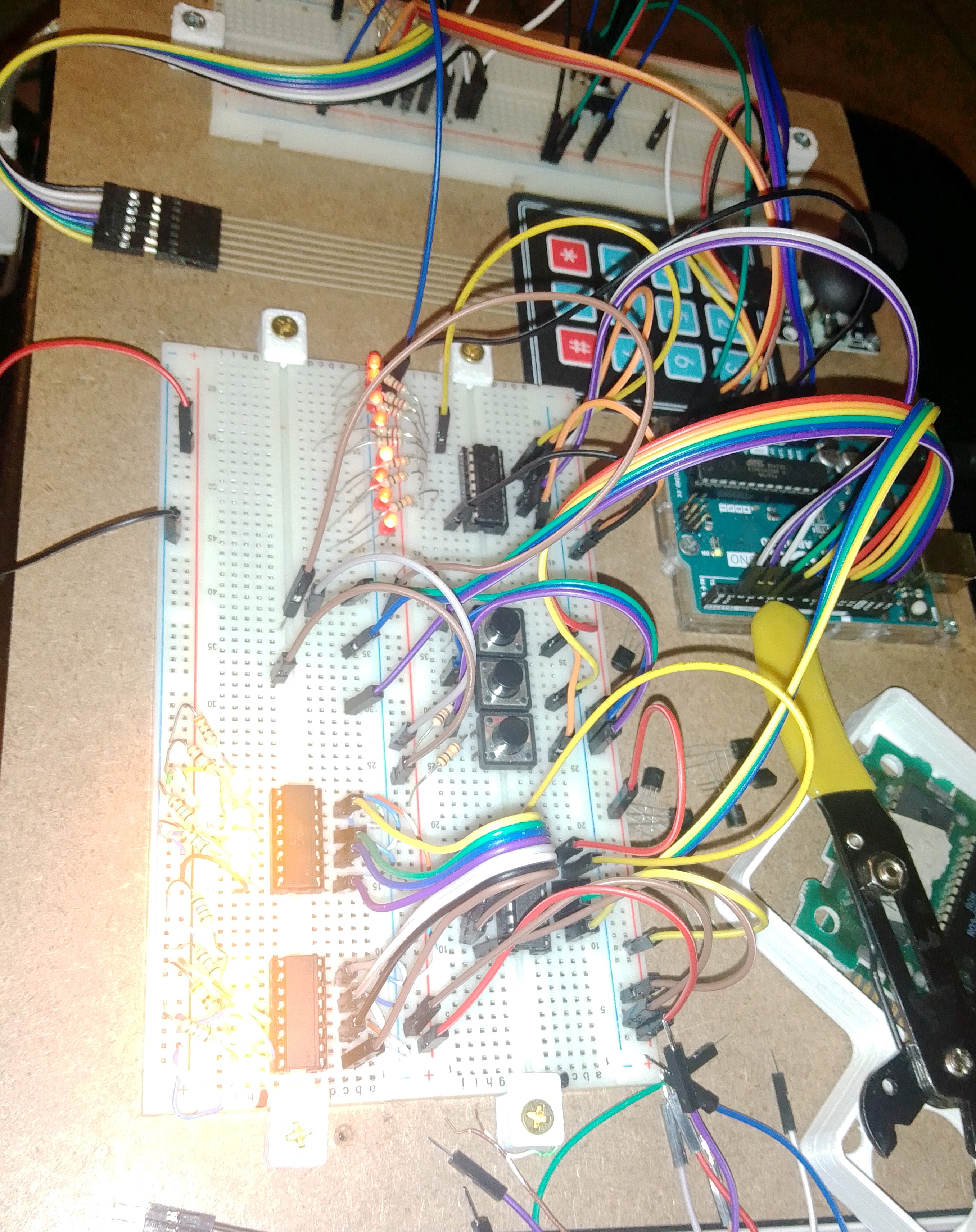
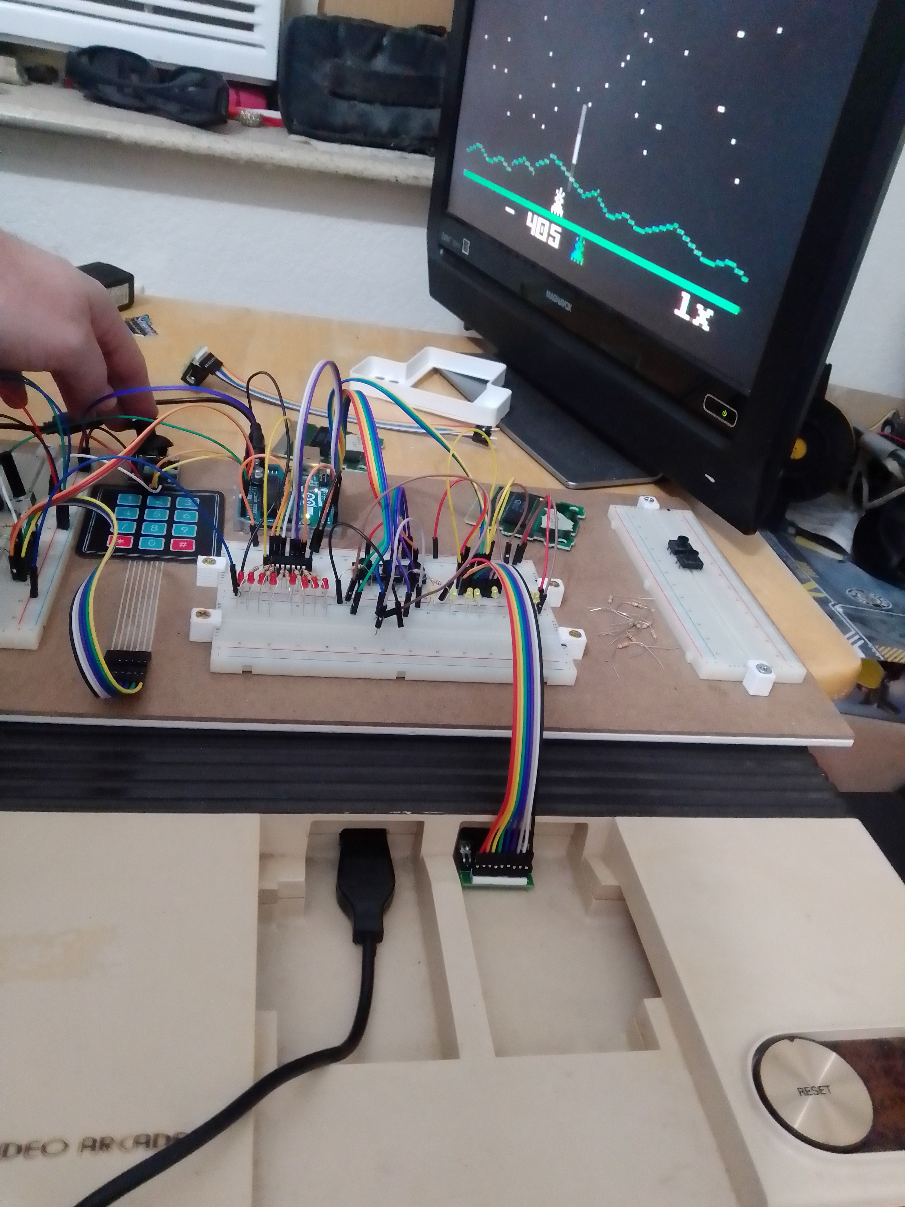
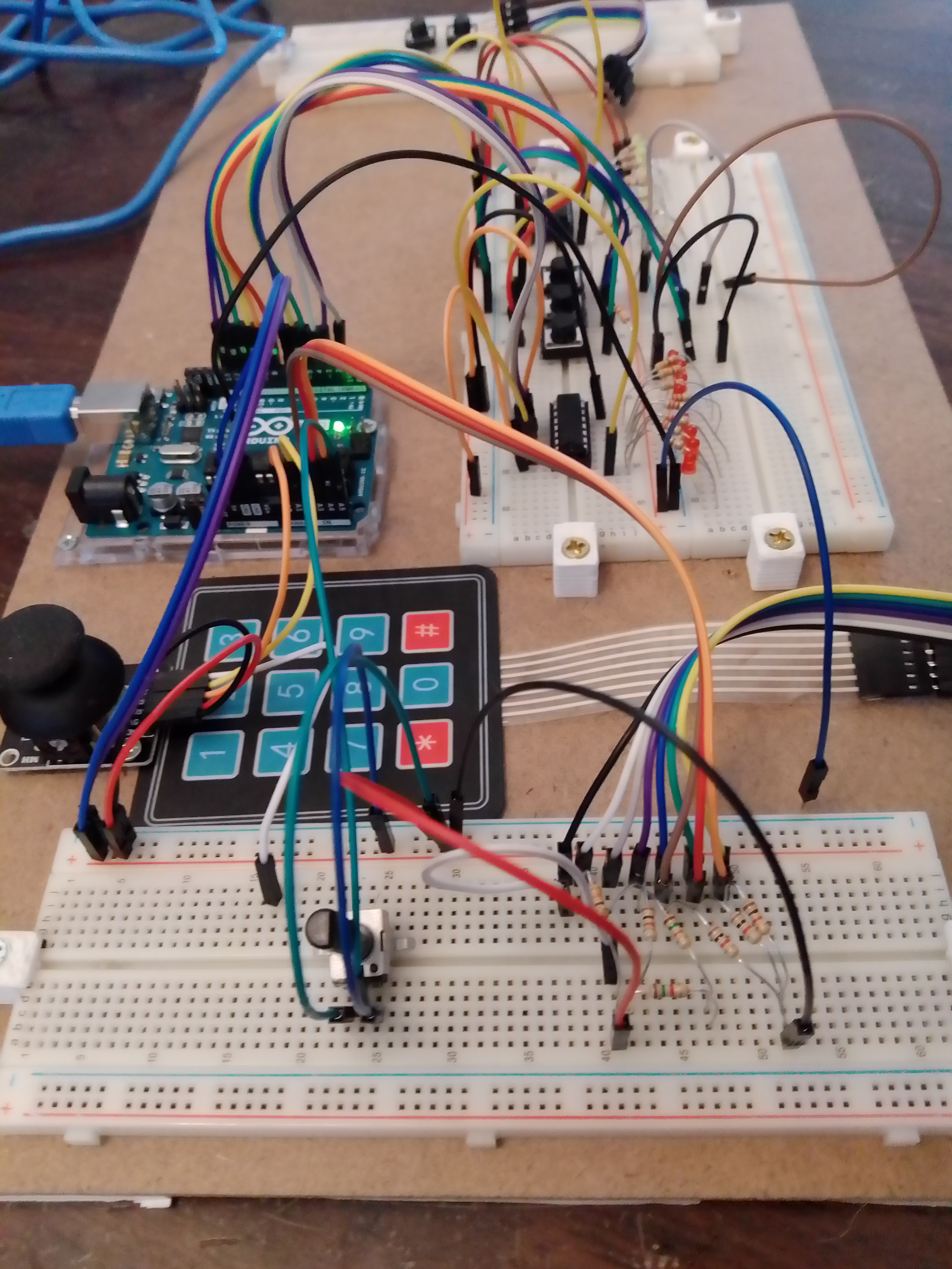
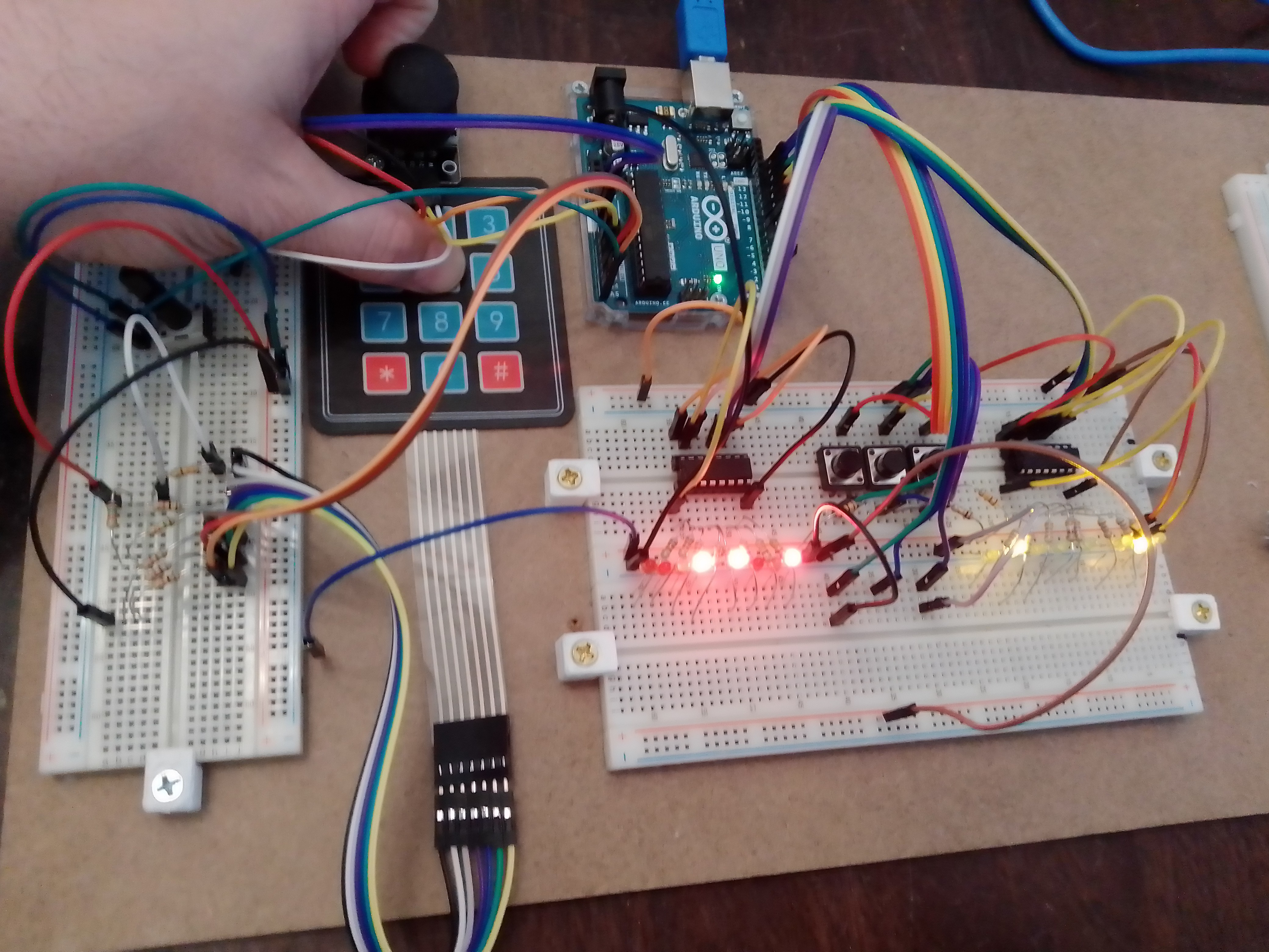
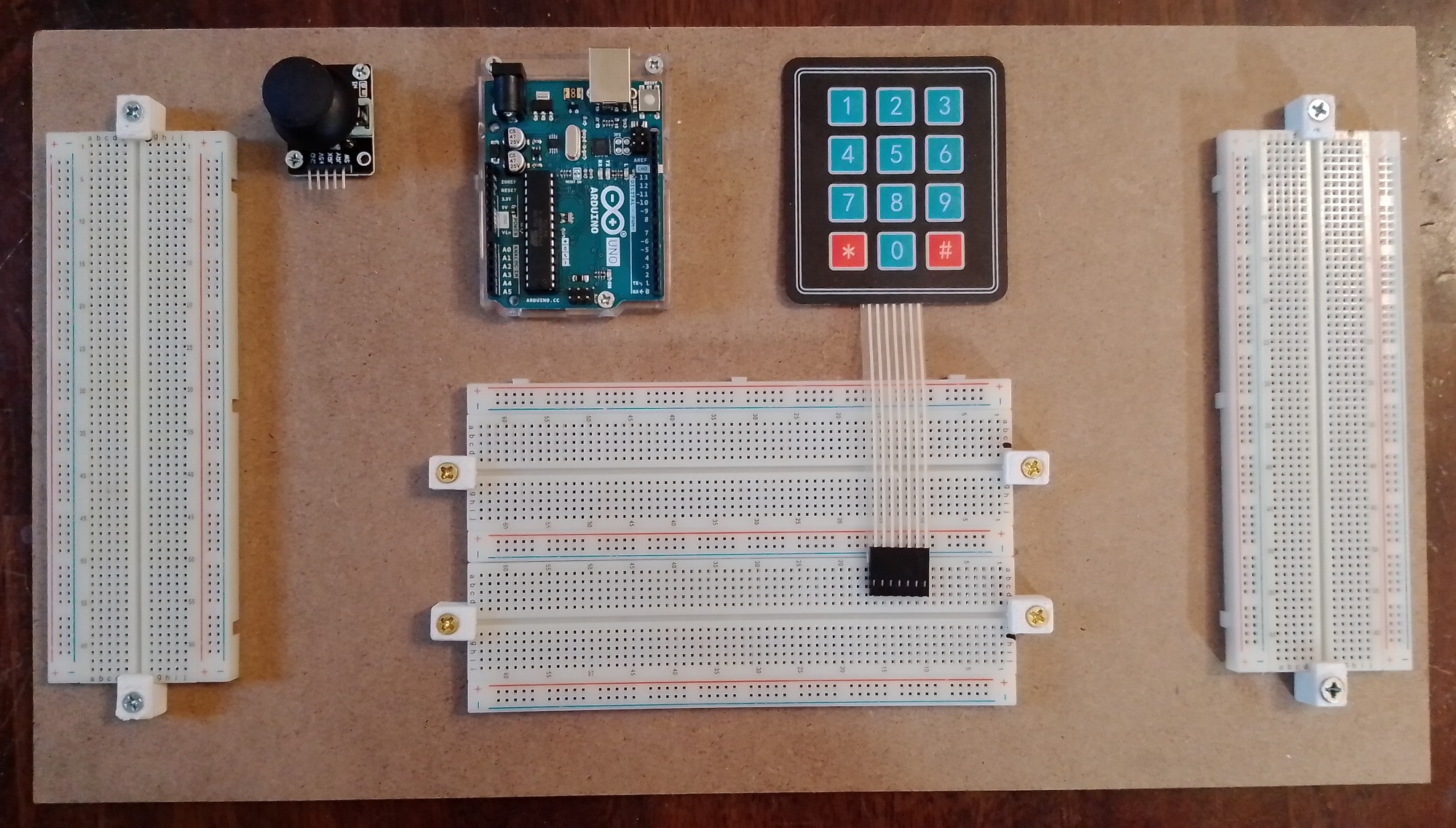
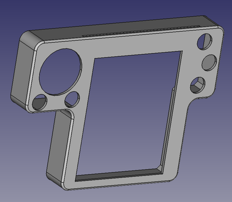
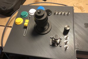
• Getting some things sorted

    deftcoyote08/23/2025 at 20:59 0 comments

    I put together a small protoboard to handle the switches, trimmer for the joystick, and the analog conversion of the keypad. It's nothing special, but it's one of the breakout boards I'll have.


    I'm to the point where I need to make some final circuit boards to test and get things working beyond breadboards. Although I want things to be really modular, the initial plan is to have the following.

    • Main board
      • keyboard analog conversion
      • 3 switches
      • 3 buttons + resistors
      • deadzone trimmer
      • joystick
    • 2 controller boards each having
      • serial communication chip
      • 2 optocouplers

    The controller boards have been done for a while, but I haven't had them printed yet. I'll make the main board and then I can actually start assembling things and actually make progress on the case.

  • Keypad Disaster

    deftcoyote06/15/2025 at 00:49 0 comments

    I assumed I could limit the travel in the low profile mechanical keys to get something I was happy with, but every attempt didn't feel correct. I put the switches and keypad on a board together, so that's what the lower traces are for. I used an engraver to make the leads. The engraver doesn't quite cut deep enough unless you run it a couple of times. Then I have to drill the holes, which is obviously tedious with a tiny drill bit.

    I then modeled and resin printed some keycaps. There were various designs to get a feel like the membrane dimples. They turned out pretty well, but as you can see from the last image, they just won't work with overlays. Also, ignore the one I broke. :)


    So for now I'm going back to a membrane keyboard, and I'm moving all the buttons and switches to a new pcb.

  • Custom Joy Pad (disc)

    deftcoyote06/15/2025 at 00:32 0 comments

    Although I'll probably just use a joystick, I did spend some time designing a custom control pad as a modular component to use. I had rather mixed results. The feel of it was great, but electronically it's not as sound as it needs to be. I should just create a membrane similar to the original, but I tried to make it a digital potentiometer instead.

    The main box design is shown with the pad being identical in size to the original.

    The circuit board is simply 5 volts in and then an evenly divided drop across 16 pads to be read by a single analog pin. The idea being to have a small membrane over it that the disc pushes on and completes the circuit. It uses the same basic design as the single common keyboard shown here: https://ardupiclab.blogspot.com/2018/11/an-analog-keypad-for-arduino.html. I do need to add a capacitor to make sure the voltage is consistent, but this was mostly for testing since I'm still planning on using a standard joystick. I'd like to get a slide-control stick (like the 3DS has), but I haven't really found one available.

    Here are the finished (rough) results. I accidentally grabbed the wrong sized resistor footprint on the pcb, and I didn't want to engrave another board, so I just mounted them up. You'll notice the connecting membrane to the out-pin is missing. That's because I didn't find a solution I liked, and figured I'd come back to it at a later date. It's been 4 months and I haven't come back to it, so I'm guessing it'll be a while.

  • Keypad Setup

    deftcoyote12/31/2024 at 12:21 0 comments

    After a lot of thought and playing around with different keypads, I think I'm going to go with low-profile mechanical keys. 

    The other options:

    • Standard electronic push buttons. I think the clickiness would be annoying, especially given how hard you have to press.
    • Soft press electronic push buttons. These are nicer but would still need custom caps to make the area feel connected. This is something I dislike about most newer intellivision controllers. I want a big square button that butts up next to the other ones.
    • Membrane keypads. This is what I originally planned on using, but they are all underwhelming and don't have enough travel in the click to feel accurate. You'd never be sure you pushed it.
    • Touch screen. Well, this is an entirely different animal that clearly has great possibilities, as demonstrated on the DS version (and homebrew DS version). Also, a recent custom INTV controller with a touchscreen was put on github, which is really well done: https://github.com/rodineyhm/IntvTouch. However, I want the tactile feel to distinguish buttons.

    I don't really like any of these options. So, my current plan is to use Gateron low-profile switches (https://www.gateron.co/products/gateron-low-profile-mechanical-switch-set) with some flat or custom keycaps. Probably something like the DOYS keycaps that have a raised circle (https://deadline.space/products/doys-keycaps). This would keep the overlays flat, but still let you feel the individual buttons before pressing, much like the original. I'll resin 3d print a bunch to see what feels the best, and it'll be nice for anyone to change the keycaps to what feels best for them.

    Here's a quick picture of the keypad board. The additional wiring and resistors is for mapping the columns to use 3 analog pins rather than 7 digital ones on the Arduino.

    The next steps are to get the keys wired up on a prototype board, start making some pcbs for testing with my cnc, and start playing with keycap shapes.

     Happy new years!

  • Early PCB setup

    deftcoyote11/23/2024 at 06:50 0 comments

    This project has been sitting there waiting for me to finish it up. I recently got an engraver that I'll use to make custom PCBs, so I finally got back into this project that has been set up in my room for months collecting dust.

    I didn't do much, but I designed the PCB for each controller board. The design is that there will be an Arduino, and a controller PCB to attach to the system. If you want the two controller input, you'd just include two PCBs. This makes it really easy to assemble it with different features.

    The board is just the 74HC595 to send 8 different signals serially over 3 pins, and then the two LTV-847 octocouplers to send the signals to the intellivision to connect pins to ground based on the input.

    I won't actually be able to make traces this tight at home, so I'll need to make a bigger one with larger traces that will need some jumpers. This is why the PCB is a bit larger and the chips are spread out. I'm not sure on my engraver how wide I need the traces to be yet.

  • Adding the optocouplers

    deftcoyote01/02/2024 at 22:56 0 comments

    Optocouplers wired for the 2nd controller. I'm having a bit of trouble with getting different outputs. Since they're all grounded to the same outputs, I think some of the pins are being affected by the others. I haven't had time to really investigate.

    I also started on the kicad schematic for the controller board. I'll have a 5-pin ribbon connecting to it with the arduino leads, power, and ground.


  • Starting Testing

    deftcoyote11/05/2023 at 04:14 0 comments

    First physical test. The left/right was working, but it was also firing when it shouldn't have been. There were clearly some wrong inputs happening. I don't actually know if the Sears model has the same controller pinout as the INTV 2. There are a few other small questions I'm not sure about, but it's coming along.

    Quick update: After discussing some issues at the atariage forums, I realize I need isolation between the console and my power supply so it doesn't damage the console over time. I had assumed I could just keep the voltage low enough, but it might still be a problem. Thus, I need some sort of isolation system. I had considered a more complicated transistor setup or just some solid state relays, but it sounds like optocouplers are going to be the easiest. The only problem with this is the size. I'd need 4 4-channel chips (16 pins each), which is a little ridiculous. I can't find a 4-channel opto-coupler where they all have the same emitter and same cathode, which is what I need. For my application, a 4-channel could be done with 4 anode pins, 1 cathode pin (as ground), 4 collector pins, 1 emitter pin (as ground), and then maybe a power/ground. So 10 pins rather than 16. I can't find a chip with this architecture though, so we may just have half the pins tied together.

  • Physical Test

    deftcoyote10/30/2023 at 00:09 0 comments

    With a bit of debugging and some code tweaks I have a physical setup working.

    List of features:

    • analog joystick working for the contol disc
    • potentiometer for adjusting the deadzone of the joystick
    • membrane keypad (this will change later)
    • the three side buttons
    • controller output for first OR second controller
    • 3 switches to control whether the output of the keypad, side buttons, or control pad should be output as first or second controller output.
    • LEDs to show high/low 8-pin output.

    The code needed to be tweaked for a few reasons. First, I used different resistor values for the analog mapping of the keypad. I also added in a bunch of debug stuff for testing the physical implementation. Finally, I was getting inconsistent output from the joystick, which I fixed by simplifying the deadzone calculations from euclidean to manhattan distance. It's much simpler and faster. The deadzone is just more of a diamond than a circle.

    Here's me pressing the control stick in a SW direction while pressing the '5' n the keypad. The joystick is outputting to controller 1 and the keypad s outputting to controller 2.

    Now I need to do output testing on an actual intellivision and then I can start designing the circuit boards. I'm thinking of having a modular circuit board arrangement, and a modular controller arrangement to accommodate left/right players and single controller output.

    • The arduino by itself (or a clone)
    • a controller output board with both SIPO chips and the 3 switches. I'm setting it up so that if someone doesn't want the controller 2 output, they can just not install the 2nd chip and the switches.
    • a board with the joystick and side buttons
    • a board with just the side side buttons

  • Getting set up

    deftcoyote10/22/2023 at 02:35 0 comments

    Not a lot to report. I finally got all the chips and parts. I was worried about having to put away things when I wasn't working on them (my desk only has so much space for my projects), so I put together a working arduino trainer for building the controller. I just 3d printed some mounting brackets from for the breadboards. I'm pretty excited to start getting everything hooked up.

    I'm also still tweaking the basic faceplate. I've printed several to get component size and feel close to correct. I'm currently on this iteration, which I'm sure barely looks different. It's actually quite a bit wider. I have been considering having the overlay holder snap on the front like the original, but I really like the feel of it being integrated as part of the controller.

    Anyway, I'll update again once I have some things wired up and I'm testing.

  • Controller Features

    deftcoyote09/24/2023 at 20:19 0 comments

    I've had a change of heart since the last log about trying to keep it to only the Arduino. The reason is because I need more output pins to have the feature of allowing input from this controller act as if it's from either the player one or player two controller. This only comes up in a few games, but basically you can't do some keypad presses while also going some directions. In certain games you'd like to use the keypad while moving. You can get around this by using both controllers because many of these games allow you to play from either one. This made some people play the game by holding both controllers!

    The current plan: use two 74HC595 SIPO chips to send output to both controllers. I'll add 3 toggle switches to control whether the keypad, action buttons, and control pad signals are sent to port one or two. This means you can even switch them while playing.

    Below is the working simulation showing 3 different inputs at the same time (I had to combine images). Keypad button '9' is being pressed, NE on the joystick is pressed, and the left bottom action button is pressed. The toggle switches on the bottom determine which output they go to. Thus, only the keypad is switched to output on controller 2.

    Although I now have 3 chips on the board, it is a nice, clean solution. And the firmware can be the same even if only one output cord is desired. The second chip and output can be an addon board that also has the 3 switches.

    The joystick continues to irk me since there isn't a good replacement for the original. I played around with adding a custom cap to a joystick to sort of replicate it (image below), but as expected, the angular movement just isn't great enough. I'm just going to have to try the thumb-slide joystick, a mini one, or experiment with something custom (as I previously mentioned).