 deftcoyote
This project has been sitting there waiting for me to finish it up. I recently got an engraver that I'll use to make custom PCBs, so I finally got back into this project that has been set up in my room for months collecting dust.
I didn't do much, but I designed the PCB for each controller board. The design is that there will be an Arduino, and a controller PCB to attach to the system. If you want the two controller input, you'd just include two PCBs. This makes it really easy to assemble it with different features.
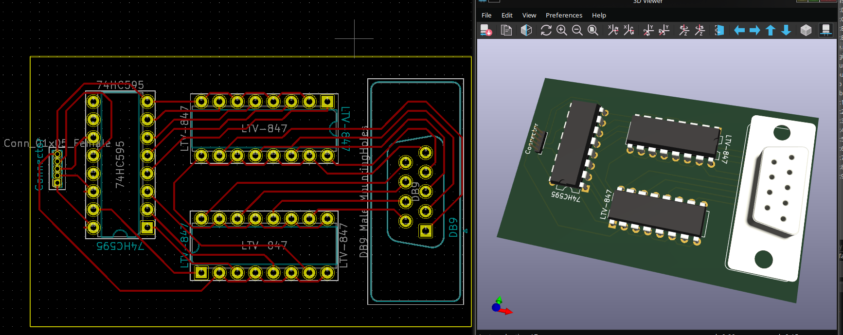
The board is just the 74HC595 to send 8 different signals serially over 3 pins, and then the two LTV-847 octocouplers to send the signals to the intellivision to connect pins to ground based on the input.
I won't actually be able to make traces this tight at home, so I'll need to make a bigger one with larger traces that will need some jumpers. This is why the PCB is a bit larger and the chips are spread out. I'm not sure on my engraver how wide I need the traces to be yet.
Discussions
Become a Hackaday.io Member
Create an account to leave a comment. Already have an account? Log In.