There are a lot of decisions to be made, so I'm going to lay out some of the ones I've made so far. A lot of research has gone into this, and I still feel like I'm usually winging it. Here are a few of the questions/decisions and some resources:
- What programmable interface are you using?
- Standard Arduino because it's easy and cheap.
- Which Arduino model (and pros/cons to each)?
- I'm just using an Arduino Uno because I have one and it's convenient. The downside is that it doesn't have enough digital pins to make this really easy, but that's minor. The idea is for someone to replace it with a Micro (or a cheaper compatible board), or to just make a small breakout board like https://www.instructables.com/How-to-make-an-Arduino-from-scratch/.
- What are you choosing for the keypad?
- As I mentioned, I'm going to use the standard 3x4 Arduino membrane keyboard.
- What are you choosing for the control pad?
- I went back and forth with this one. For now, I'm just using a standard analog joystick (https://www.sparkfun.com/products/9032), Maybe I'll try a mini one like in the Switch, PSP, etc.
- I would also like to consider a thumb-slide joystick (https://www.sparkfun.com/products/9426). My worry with the thumb-slide is long-term use, but I still want to see how it plays.
- In the future I may also consider something like a click wheel from the 1st gen ipods, or map the capacitive touch from newer ones. There are rotary encoder wheels (https://www.adafruit.com/product/5001).
- I can't seem to find any flat control pad based on pressure (other than touchpad ones like the steam controller). The closest may be a soft circular potentiometer (https://www.adafruit.com/product/1069), which I could use very similar to the original controller pad.
- Buttons are still buttons, right?
- Not much to do with action buttons except have them.
- What are the main constraints related to output?
- For output, the Intellivision needs 9 pins (really just 8 "data" pins). The controller has power and 8 pins that it grounds in combinations to detect which button was pressed. See https://forums.atariage.com/topic/169018-replacement-controller-ideas/ and https://www.raphnet.net/electronique/intellivusb/index_en.php for an overview of this.
- In the Sears model and INTV II, they used DB9 connections. I'm thinking of using the DB9 and just having a small adapter for the INTV I. or vice versa. To see their relation, check https://moddedbybacteria.wordpress.com/mattel-intelivision/
- What are the input constraints?
- Usually, the keypad uses 7 digital input pins.
- The joystick uses 2 analog pins.
- The 3 buttons use 3 digital pins.
- So what's the problem with the pins?
- There are only 13 digital I/O pins and 6 analog I/O pins. If I use 8 pins as output for the controller, then I don't have enough digital I/O pins for the keypad.
- There are several options to get around this. In the most extreme case, you could actually get all the input with only 4 analog pins, but there'd be latency issues.
- Use a shift register (like the 74HC165 or 74HC595) to get more I/O pins. See https://www.digikey.com/en/maker/blogs/2022/how-to-add-more-digital-gpio-pins-to-arduino-projects-using-shift-registers and https://www.circuitbasics.com/how-to-use-shift-registers-on-the-arduino/.
- Make use of the analog pins through various voltages. With this, I can read the keypad with 3 analog pins (could actually use 1, but not as efficient) https://ardupiclab.blogspot.com/2018/11/an-analog-keypad-for-arduino.html.
- Make use of an analog pin for the buttons.
- What's the plan, then?
- I'd like to make the circuit as simple as possible (so fewer chips). Thus, the current plan is:
- 3 analog pins for the keypad
- 2 analog pins for the joystick
- 3 digital pins for the buttons
- 8 (or 9?) digital pins for the controller output.
- I'd like to make the circuit as simple as possible (so fewer chips). Thus, the current plan is:
- Any testing?
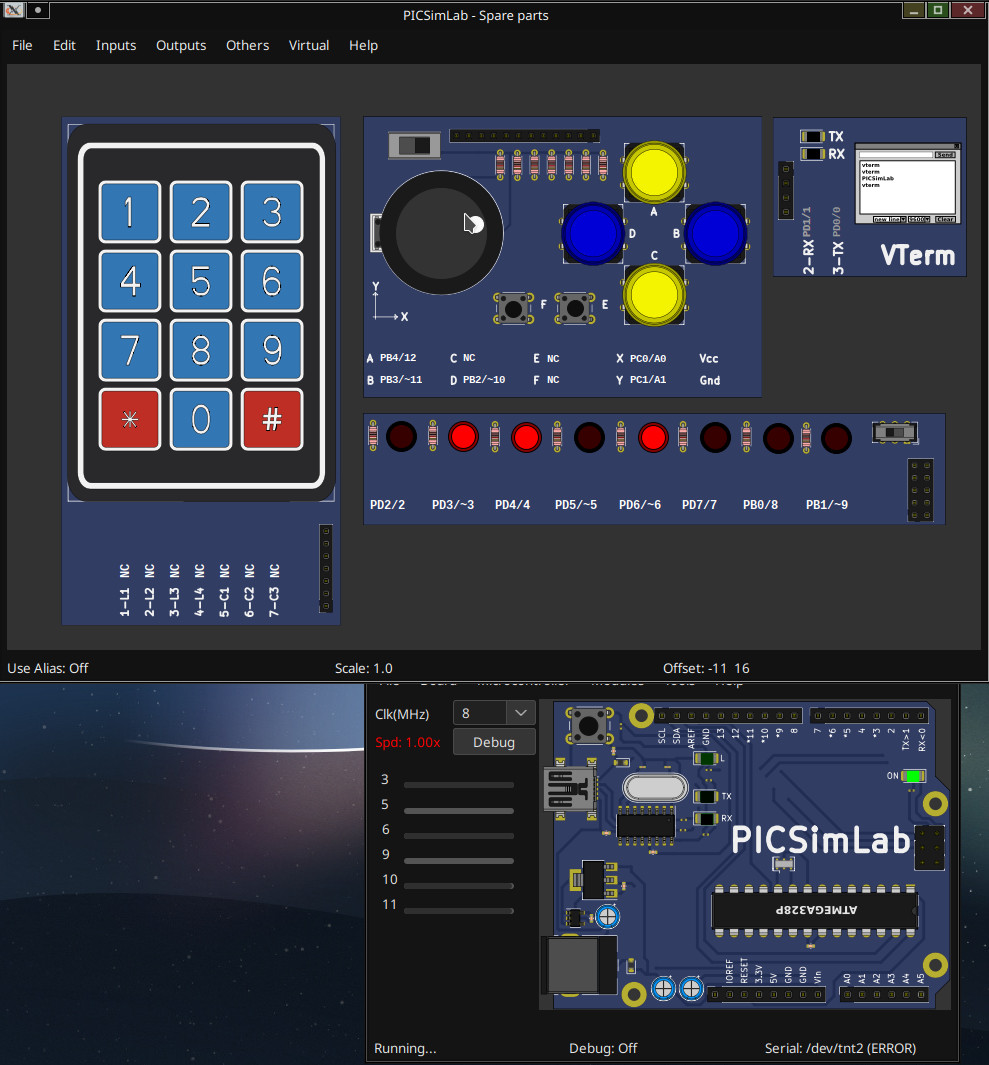
- I've been using PICSimLab (https://github.com/lcgamboa/picsimlab) for initial testing before I start breadboarding stuff. You can see the setup below, but there's no way to hook up the keypad through analog in the software, so this is mostly just testing the joystick and buttons. I have the Arduino code mostly finished. In the picture below, you can see the 3 pins for the NW diagonal lighting up. I'm just using LEDs to represent output- and I think they're actually reversed (supposed to be high normally), but this is a simple toggle in my code.
- How is the joystick mapped?
- The joystick mapping involves checking the distance from the center and ignoring anything inside a dead zone threshold. Then, it uses the X and Y to calculate the rotational angle from the top (north). Then it checks which of the 16 zones that angle is in (out of 360). Then it sets the correct bits for that zone.
- Are there any extensions to the controller planned?
- I could allow several programmable features based on a program button and a keypad press.
- I could also just add a few extra buttons for convenience.
- What features are you adding?
- A way to change the size of the joystick dead zone. Either through the keypad or a trimmer.
- I could add alternate output formats. A way to switch between the INTV, Atari 2600, etc.
- As suggested by Joe Z., a way to output as if it was the 2nd controller. I think this is only needed for either the keypad or the control pad. This is possible with an addon cord and 2 switches on the back of the controller saying whether the keypad and control pad should be sent as 1st or 2nd player (if both switches are on 2, then it's just like having only the 2nd player controller).
- All of these could be done with a single program button, but I think it would be nice to change some of them while playing.
- Have you considered just making the controller modular?
- That's what the 3d prints were about last time. I could, indeed, just have snap on pieces for different types of joysticks, buttons, options, etc., but this is getting to be too much.
- When are you uploading all this stuff?
- When something is working. That way people can modify and customize stuff to their liking- and probably make it better than me. Then I can use what they do.
- Power?
- Surely some will be needed and I haven't thought about it. I don't want to have a power cord to the wall though.
- Any more 3d work, because I bet you want to show it off?
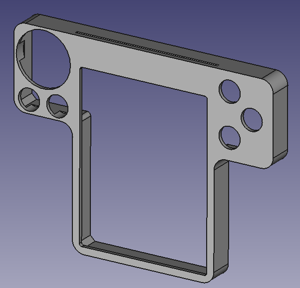
- You are correct. See below for the design 3, which I'm still not sure I like more than 2.5 (the hybrid 3d model from last time). This work is being done in FreeCAD.
The basic setup in PICSimLab. This is showing the pins lighting up with the joystick movement. All 16 positions and their bits are mapped.

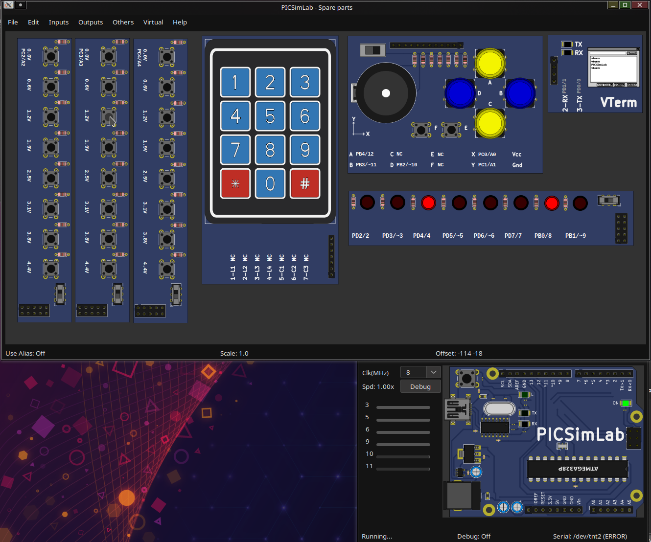
In order to simulate testing the keypad, there are rows of buttons set up for analog logic. Thus, in the 2nd picture you can see three of them set up to represent the columns of the keypad- this way I can test out the code. I only use the top 4 buttons in each of the components. Here, I'm pressing the equivalent '8' key and you can see the correct pins light up.

Design 3, which is only a slight variation over the previous one. At some point, I'll need to redesign for ergonomics, but relational placement is all these 3d models are testing.

 deftcoyote
Discussions
Become a Hackaday.io Member
Create an account to leave a comment. Already have an account? Log In.