 BastelBaus
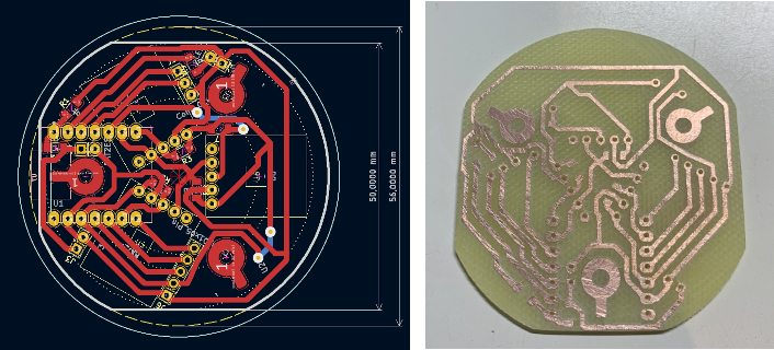
The full setup was a bit fragile to debug so I decided to do a design iteration. First Step was to update the PCB by
- adding some space at teh sides to allow mounting
- added battery connections, switches and LED as well as 6D IMU connection
- a cleaner milling process by also clearing the intermediate copper areas
- and still single sided to make milling easier ...
 Then I designed distance blocks to let the magnetic sensors be glued to the PCB. This worked quite nice
 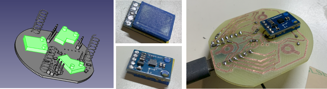 The ESP32S3 I mounted the same way, included the two wires for the battery connection (which had been rotated :-( in the design):
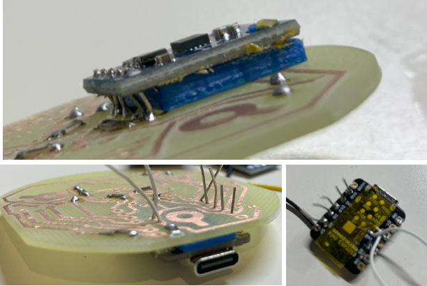 Then the base mount design followed; threaded inserts to but two half blocks together. Inside the metal weight block, the battery and on the top the PCB. The Base holds also the LED and the power switch. The push buttons and the IMU I plan to mount in the head.
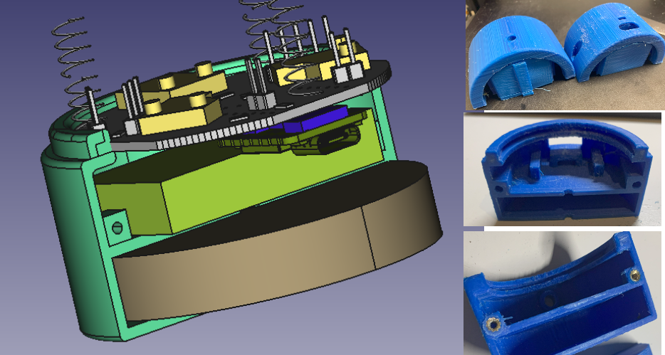 In general it worked quite good, the only problem was that the dimensions had been to small (shrinkage of the ABS I used?) and I had to print three times and still the base slightly broke. BNut sufficient to continue testing. You can see the LED in the middle picture and the battery on/off switch on the right hand side picture.
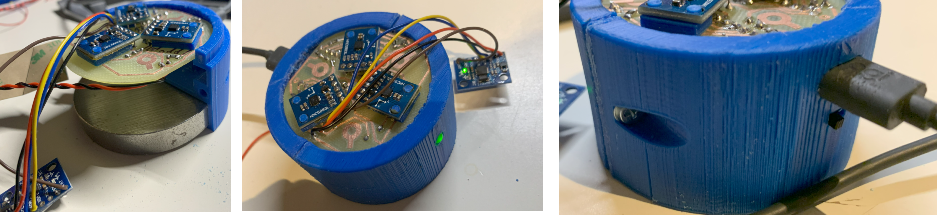 Learnings:
- housing dimensions not yet sufficient
- Antenna had to go on top of the battery, I will have add a compartment where I could put the antenna on the outside.
Discussions
Become a Hackaday.io Member
Create an account to leave a comment. Already have an account? Log In.