 BastelBaus
Good discussions with my hidden co-creator made clear that there are three to four possible options to follow to derive the conversion matrix from the 3x3D magnetic sensors to teh 6D displacement of the know:
- Use simulation to derive converstion matrix
- Use a mechanical defined displacement (i.e. in a kind of end stops, an external actuator, ...) to have a mechanical defined displacement and use these defined positions to calibrate the conversion matrix
- Use the IMU in the TOP to estimate displacement and derive from this the groudn truth to derive the conversion matrix
- Use the pure measurement data and statistical analysis (i.e. a principal component analyisis: PCA) to derive the conversion matrix from the magnetic sensors to the displacements
Simulation would probably be the easiest but I am note sure if this would be exect enough. mechanical would be the most precise but possible a lot of effort. The IMU could work (at least for the three rotations but might have additional errors by the IMU (especially when integrating the rate signals or even the accelerations twice. The pure statistical approach might bee the most elegant one, but probably quite hard and maybe not accurate enough.
I am myself not sure what to to next, so stay tuned and follow the next results !
[some hours later ... ]
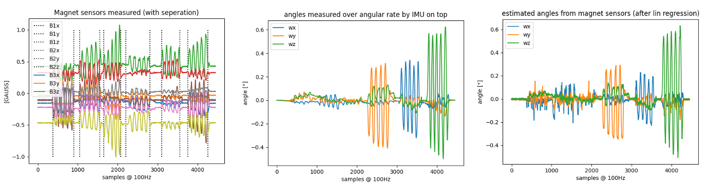
PCA did not really work, but using the IMU at least for the rotation axes did not give too bad results (not at all finished but a good way to continue!):
 Description
- left: the 3x3D magnet signals for the test recording, where i sub-sequential moved the top in all degrees of freedom
- middle: the integrated angular rate from the IMU in all three dimensions I used as ground truth for the regression
- right: the resulting estimate of the top movement only based in the magnetic sensors (and of course the regression result)
Discussions
Become a Hackaday.io Member
Create an account to leave a comment. Already have an account? Log In.