Close
0%
0%

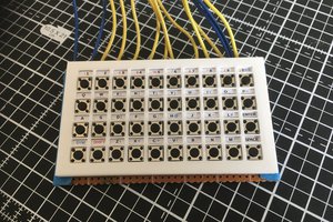
A Tile Based MacroPad

Using "magic" tiles to assign keystrokes to this MacroPad's keys.

Similar projects worth following
Having just finished my Turing Machine Demonstrator Mark 3 project (https://hackaday.io/project/191649-tmd-3-turing-machine-demonstrator-mark-3), I was looking for a more practical application for the tile based interface I used there. Well here is what I came up with.

Overview

MacroPads have been a hot topic for years now as part of the tremendous continuing interest in custom keyboards. Search Hackaday for "macropad" and thanks in large part to  you will get pages and pages of blog entries with lots of cool designs (bananas and corn and sunflowers oh my).  A similar search of Instructables returns 27 MacroPad results. With software like QMK or Kaleidoscope to ease the burden of creating and configuring the MacroPad firmware, and cheap microcontrollers like the Arduino Pro Micro or Raspberry Pi RP2040 this shouldn't come as a surprise to anyone.

The reason that I'm jumping into an already very busy category is that I think that a tile based interface solves a couple of shortcomings common to all MacroPads. 

Labels/Legends

If the MacroPad is a simple add-on number pad, then it's easy to find keycaps with the appropriate legends to populate it.
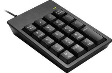
For MacroPads that are meant to be programmed with arbitrary user selected macros, then the legends become a concern.  What does a "Check Inventory" button look like? Most commercial MacroPad offerings skirt the issue by shipping with attractively color coordinated blank keycaps leaving the user to memorize the function of each key.
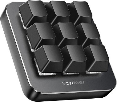
There are other solutions. For instance, at the high end, from these very pages, "ADAPTIVE MACRO-PAD USES TINY OLED SCREENS AS KEYCAPS".
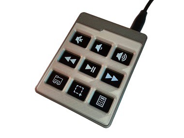
Cool except for the high per key cost and complexity. 

Another simpler and cheaper solution is Relegendable Keycaps. The clear plastic caps allow you to create and insert printed text or icons.
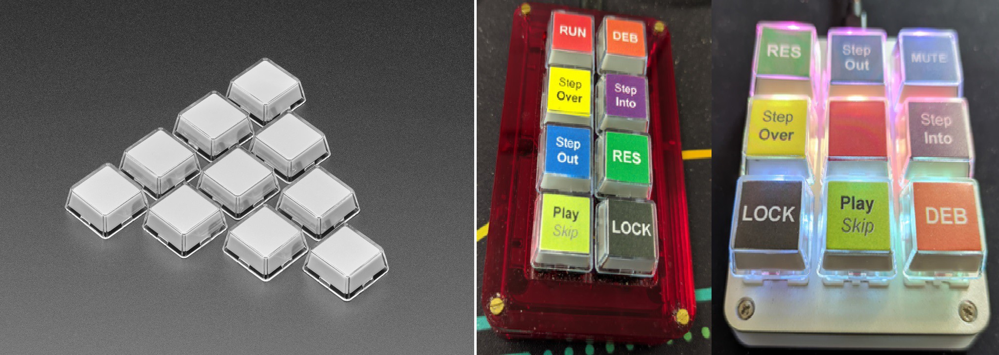
This is a pretty good solution, but it only works if the number of macros you want is less than or equal to the number of keys on the MacroPad. Which brings us to the second problem.

Many Macros/Few Keys

Once you begin using a MacroPad you start thinking about all the useful macros that you would like to use. You soon run out of keys to map the macros to. Configuration software like QMK solves this problem with layers. Layers allow the user to define multiple sets of macros for the keys available. Typically one key is assigned to switch between layers in one of the following manners:

  • only for the next key press
  • as long as the layer switch key is pressed
  • till the toggle key is pressed again (there could be many layers)

One problem here is that a layer typically applies to all of the keys on the MacroPad. So when you switch the layer all of the key's macros change. Think of how this really exacerbates the legend issue. The user must remember all of the key macro assignments based on these hidden layers as the keycaps (except for the ones with tiny OLED screens) will be wrong.

So what is the solution?

A Tile Based Interface

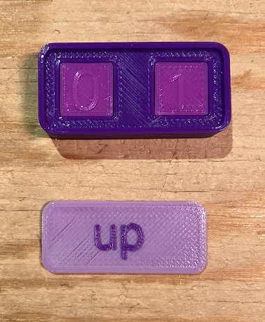
My MacroPad has eight keys based on nice Fubata MD-4PCS switches. Beside each key is a slot that can hold a "special" tile which identifies a macro to be associated with that key. To be perfectly clear, all of the available macros will be defined in the firmware in much the same way as with other MacroPads. The tile holds a "simple numeric value" that maps the associated key to a specific internally defined macro sequence when the tile is inserted into the slot (details to follow).
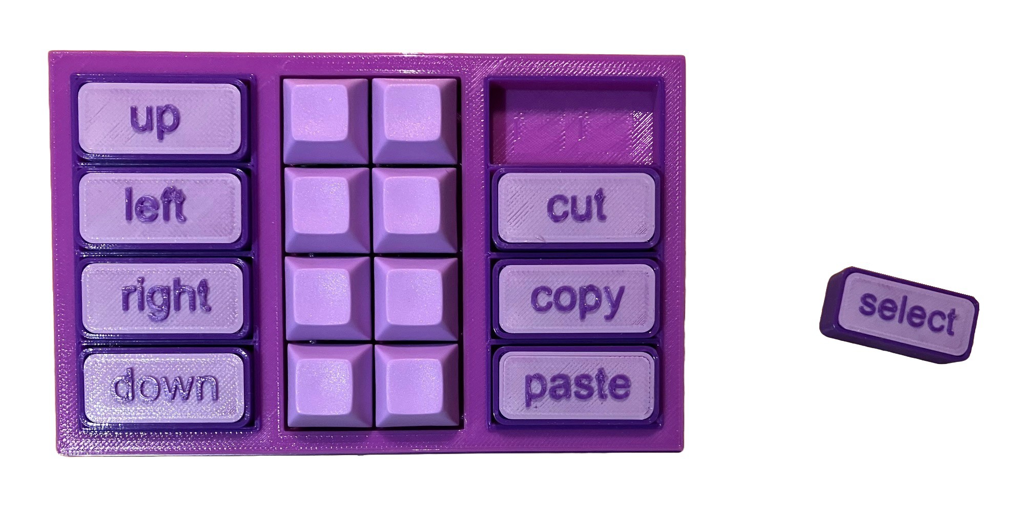
Tiles can be swapped at any time changing the key's macro immediately. I'm a big fan of this tactile based interface. 

It's pretty obvious how this solves the few keys many macros problem. The user can define a large number of macros (I think up to 64 at this point) internally and can activate any eight macros at a time by simply slotting in the appropriate tiles.  

Furthermore the tile's approximately 2U size (necessary for technical reasons) is a great surface for defining meaningful, easy to understand, labels for the macro's action. Of course if you are attached to cool but cryptic icons you can do that too.

If there is any downside, it's that the tiles do take up a...

Read more »

  • Finishing Touches

    Michael Gardi10/06/2023 at 00:11 0 comments

    When I did the wiring, I chose to use jumper wires to connect to the proMico rather than soldering directly to the header. I was glad that I did because the USB connector on the pro Micro broke and I had to replace the board. At any rate the jumper wires extended below the bottom of the case, so I added some rubber feet which not only fixed that issue, it made the box more stable.

    I cleaned up the MacroPad sketch and created a Configure_MicroPad sketch to help calibrate the linear hall effect sensors (see Calibration log). I also added auto repeat functionality.

  • Calibration

    Michael Gardi10/05/2023 at 15:54 0 comments

    In order to get accurate tile readings, it's important to calibrate the linear hall effect sensors. I found with my TMD-3 project that for the best results each sensor should have its own calibration values for each of the possible tile variations.  With 16 sensors and 10 possible tile variants this can be a pretty tedious process.  So to make things easier I create a calibration sketch. NOTE that you only have to do this calibration once.

    To start I create a special set of calibration tiles.

    Each tile contains two magnet holders set to the number that appears in the label. 

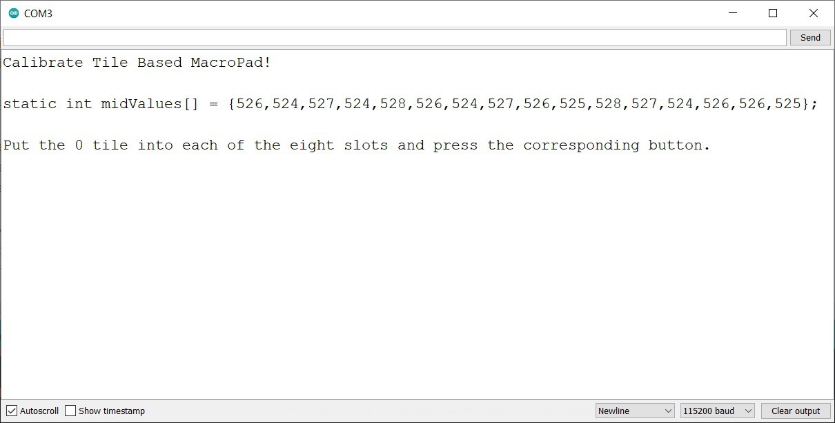
    The calibration program runs from the Arduino IDE and outputs to the Serial monitor.  With NO tiles in the MacroPad when the program first starts up you see the following:

    The midValues array printed represents the "at rest" or no magnet present readings from the hall effect sensors. Notice that the values do not vary much between sensors. This table should be copied into the MacroPad sketch replacing the existing table with freshly calibrated values.

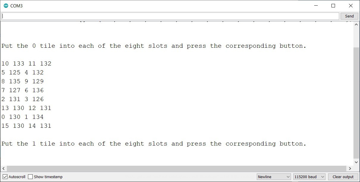
    Following the prompt, when you put the "zero" tile into each of the eight slots and press the corresponding buttons, you should see something like:

    For each button pressed the two sensors for that button are read and the sensor numbers and values are emitted. When all eight slots have been calibrated the next tile number is asked for.

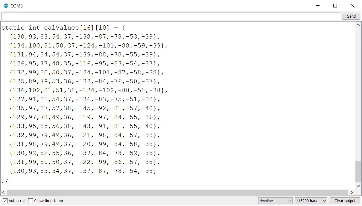
    When all ten tiles have been calibrated the calValues table is emitted.

    Simply cut the table text from the Serial window and paste it into the MacroPad sketch replacing the existing table. 

    The MacroPad should now be setup to accurately read tiles and correctly map them to the defines macros.

    I have posted the Calibrate_MacroPad.ino sketch to GitHub.

  • Even More Magical Tiles

    Michael Gardi10/02/2023 at 21:59 0 comments

    When doing the firmware I ended up deciding that the encoded tile number would be used as an index into the macros table of macro strings. But because each of the two digits in a tile could only go up to 8, it meant that the macro table ended up having gaps marked "Skip for now.".

     // Define the macros here.
    String macros[] = {
      "PRESS,KEY_LEFT_CTRL,a,RELEASE_ALL", // select
      "PRESS,KEY_LEFT_CTRL,c,RELEASE_ALL", // copy
      "PRESS,KEY_LEFT_CTRL,x,RELEASE_ALL", // cut
      "PRESS,KEY_LEFT_CTRL,v,RELEASE_ALL", // paste
      "KEY_UP_ARROW",                      // up
      "KEY_LEFT_ARROW",                    // left
      "KEY_RIGHT_ARROW",                   // right
      "KEY_DOWN_ARROW",                    // down
      "",                                  // Skip for now.
      "",                                  // Skip for now.
      "MEDIA_VOLUME_UP",                   // louder 
      "MEDIA_VOLUME_DOWN",                 // softer
      "MEDIA_MUTE",                        // mute
      "MEDIA_PLAY_PAUSE",                  // pause/play
      ""
    };

    No big deal but also easily fixed. I decide to add another magnet holder to the mix which would allow two more numbers per tile side. 

    When looking at the readings from one side of an existing tile:

     136, 72, 54, 37, -123, -87, -56, -37

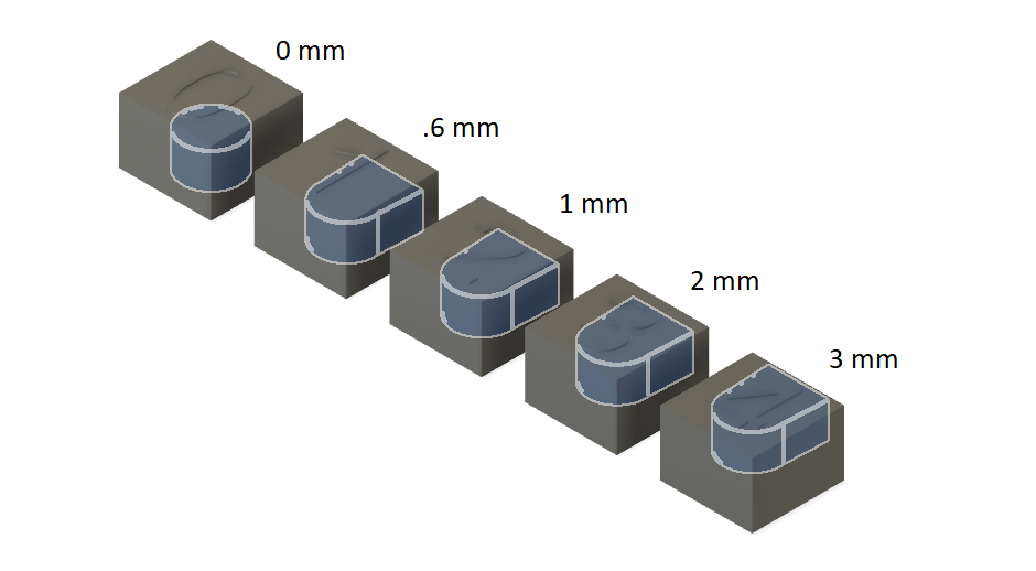
    you can see that there is a pretty big "gap" between the first two numbers and the fifth and six numbers.  This represents the difference in distance from the sensor between 0 mm and 1 mm.  So I added another magnet holder with the distance set to .6 mm. Here is my new set of holders:

     With ten digits per magnet, I can now have up to 100 macros stored, and no gaps in the macros table. 

  • Firmware

    Michael Gardi10/02/2023 at 17:39 0 comments

    I have posted an initial version of the Arduino based firmware to GitHub. It handles the reading of the tiles, and assigns the macros to specific keys.  I'm using the Arduino HID-Project library to send the keys via USB to the PC. This is working well. 

    When I started looking at similar MacroPad projects, at least the ones that were not based on QMK or Kaleidoscope, I found that they were all virtually mapping keys directly to some code. For instance:

    switch(button){
        case '1':  //Return
          Keyboard.press(KEY_RETURN);
          Keyboard.releaseAll();
          break;
        case '2':  //Escape
          Keyboard.press(KEY_ESC);
          Keyboard.releaseAll();
          break;
        default:
          break;
      };

    For every macro added or changed then the code would get modified. Not a big deal but it could be easier, especially maybe for non-programmers.  In my implementation the user can define the macros as comma delimited strings. Here are my macro definitions so far. 

    It starts with the definition of keyboard and media codes.

    /*****
    * Standard Key Codes.
    ******
    KEY_RESERVED               KEY_ENTER                   KEY_PAGE_DOWN                            
    KEY_ERROR_ROLLOVER         KEY_RETURN                  KEY_RIGHT_ARROW                          
    KEY_POST_FAIL              KEY_ESC                     KEY_LEFT_ARROW                           
    KEY_ERROR_UNDEFINED        KEY_BACKSPACE               KEY_DOWN_ARROW                           
    KEY_A                      KEY_TAB                     KEY_UP_ARROW                             
    KEY_B                      KEY_SPACE                   KEY_RIGHT                                
    KEY_C                      KEY_MINUS                   KEY_LEFT                                 
    KEY_D                      KEY_EQUAL                   KEY_DOWN                                 
    KEY_E                      KEY_LEFT_BRACE              KEY_UP                                   
    KEY_F                      KEY_RIGHT_BRACE             KEY_NUM_LOCK                             
    KEY_G                      KEY_BACKSLASH               KEYPAD_DIVIDE                            
    KEY_H                      KEY_NON_US_NUM              KEYPAD_MULTIPLY                          
    KEY_I                      KEY_SEMICOLON               KEYPAD_SUBTRACT                          
    KEY_J                      KEY_QUOTE                   KEYPAD_ADD                               
    KEY_K                      KEY_TILDE                   KEYPAD_ENTER                             
    KEY_L                      KEY_COMMA                   KEYPAD_1                                 
    KEY_M                      KEY_PERIOD                  KEYPAD_2                                 
    KEY_N                      KEY_SLASH                   KEYPAD_3                                 
    KEY_O                      KEY_CAPS_LOCK               KEYPAD_4                                 
    KEY_P                      KEY_F1                      KEYPAD_5                                 
    KEY_Q                      KEY_F2                      KEYPAD_6                                 
    KEY_R                      KEY_F3                      KEYPAD_7                                 
    KEY_S                      KEY_F4                      KEYPAD_8                                 
    KEY_T                      KEY_F5                      KEYPAD_9                                 
    KEY_U                      KEY_F6                      KEYPAD_0                                 
    KEY_V                      KEY_F7                      KEYPAD_DOT                               
    KEY_W                      KEY_F8                      KEY_NON_US                               
    KEY_X                      KEY_F9                      KEY_APPLICATION                          
    KEY_Y                      KEY_F10                     KEY_MENU                                 
    KEY_Z                      KEY_F11                                            
    KEY_1                      KEY_F12                                            
    KEY_2                      KEY_PRINT                                          
    KEY_3                      KEY_PRINTSCREEN                                    
    KEY_4                      KEY_SCROLL_LOCK                                    
    KEY_5                      KEY_PAUSE                                          
    KEY_6                      KEY_INSERT                                         
    KEY_7                      KEY_HOME                                           
    KEY_8                      KEY_PAGE_UP                                        
    KEY_9                      KEY_DELETE                                         
    KEY_0                      KEY_END 
    
    
    You can add any of these codes to the keyboard lists below for use in macro definitions.
    In the keyboardKeyNames table add the code as a string delimited by "".
    In the keyboardKeyCodes table ad the code as is without quotes.
    Don't forget the commas at the end of each entry.
    It is IMPORTANT to add the name and code in the same position in the list.
    *****/
    
    String keyboardKeyNames[] = {
      "KEY_LEFT_CTRL",
      "KEY_UP_ARROW",
      "KEY_DOWN_ARROW",
      "KEY_LEFT_ARROW",
      "KEY_RIGHT_ARROW"
    };
    
    KeyboardKeycode keyboardKeyCodes[] {
      KEY_LEFT_CTRL,
      KEY_UP_ARROW,
      KEY_DOWN_ARROW,
      KEY_LEFT_ARROW,
      KEY_RIGHT_ARROW
    };
    
    /******
    * Media Key Codes.
    *******
    MEDIA_RECORD             MEDIA_VOLUME_MUTE    
    MEDIA_FAST_FORWARD       MEDIA_VOL_MUTE        
    MEDIA_REWIND             MEDIA_VOLUME_UP        
    MEDIA_NEXT               MEDIA_VOL_UP        
    MEDIA_PREVIOUS           MEDIA_VOLUME_DOWN    
    MEDIA_PREV               MEDIA_VOL_DOWN        
    MEDIA_STOP        
    MEDIA_PLAY_PAUSE    
    MEDIA_PAUSE        
    
    You can add any of these codes to the media lists below for use in macro definitions.
    In the consumerKeyNames table add the code as a string delimited by "".
    In the consumerKeyCodes table ad the code as is without quotes.
    Don't forget the commas at the end of each entry.
    It is IMPORTANT to add the name and code in the same position in the list.
    *****/
    
    String consumerKeyNames[] = {
      "MEDIA_PLAY_PAUSE",
      "MEDIA_VOL_MUTE",
      "MEDIA_VOLUME_UP",
      "MEDIA_VOLUME_DOWN"
    };
    
    ConsumerKeycode consumerKeyCodes[]{
      MEDIA_PLAY_PAUSE,
      MEDIA_VOL_MUTE,
      MEDIA_VOLUME_UP,
      MEDIA_VOLUME_DOWN
    };
    
    /*****
    * Define the macros here.
    *****
    String macros[] = {
      "PRESS,KEY_LEFT_CTRL,a,RELEASE_ALL",  // select
      "PRESS,KEY_LEFT_CTRL,c,RELEASE_ALL",  // copy
      "PRESS,KEY_LEFT_CTRL,x,RELEASE_ALL",  // cut
      "PRESS,KEY_LEFT_CTRL,v,RELEASE_ALL",  // paste
      "KEY_UP_ARROW",                       // up
      "KEY_LEFT_ARROW",                     // left
      "KEY_RIGHT_ARROW",                    // right
      "KEY_DOWN_ARROW",                     // down
      "",                                   // Skip for now.
      "",                                   // Skip for now.
     "MEDIA_VOLUME_DOWN",...
    Read more »

  • Wiring

    Michael Gardi09/28/2023 at 17:23 0 comments

    The first thing I did was to trim the leads on the SS49E sensors and spread them out a bit for easier access.

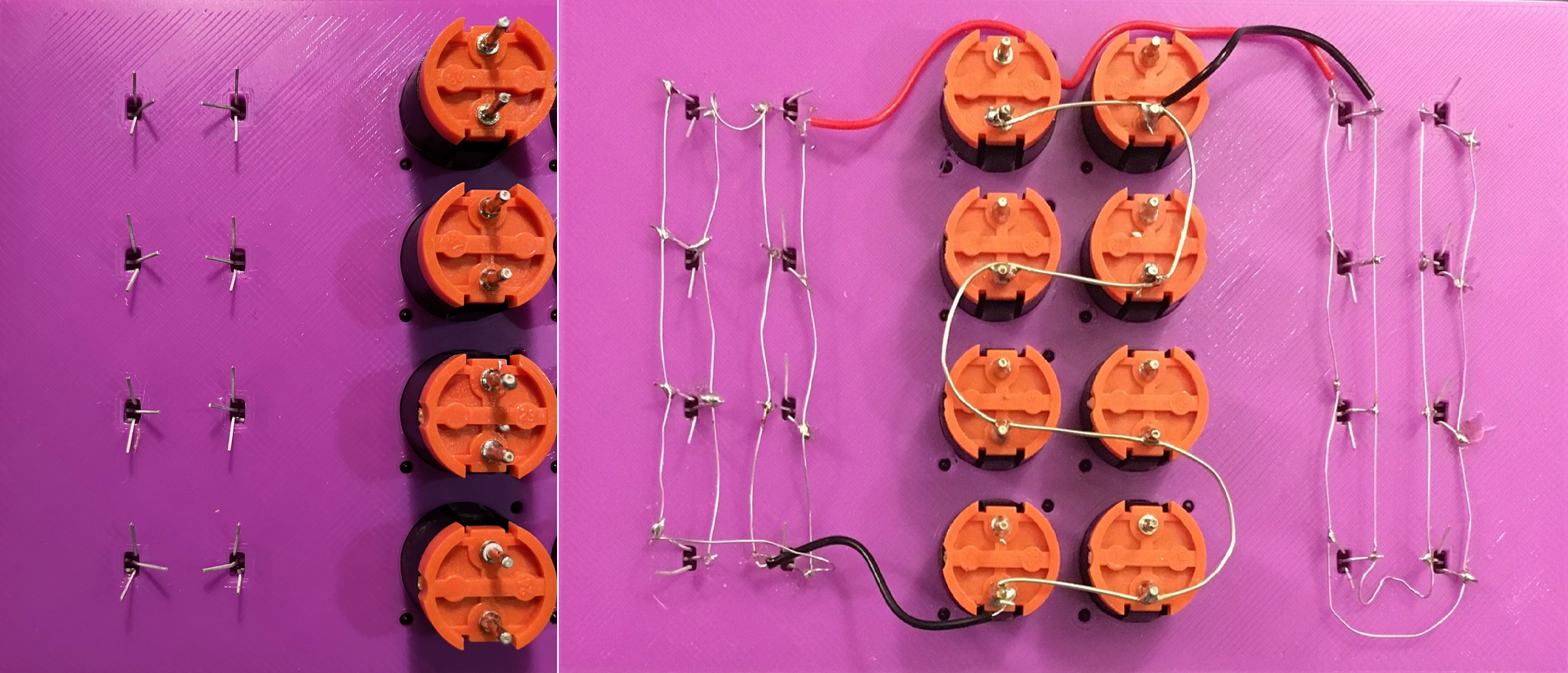
    Then I wired the power connections to all the sensors and the buttons. Obviously a lot of care was taken not to introduce shorts, especially with the tiny hall effect sensors. The perfectionist in me cringes a bit looking at this, but I am determined to keep the BOM down so point-to-point wiring it is.

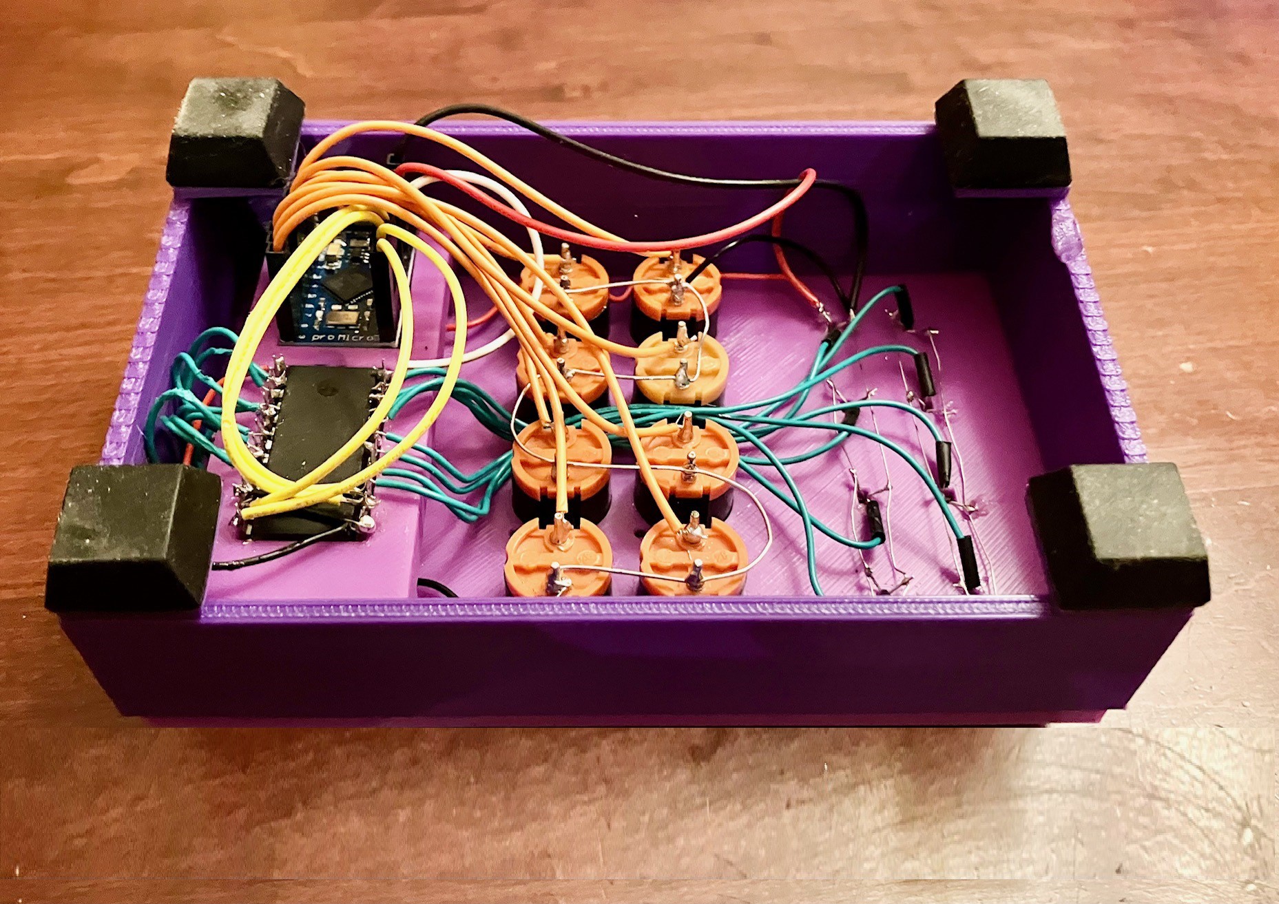
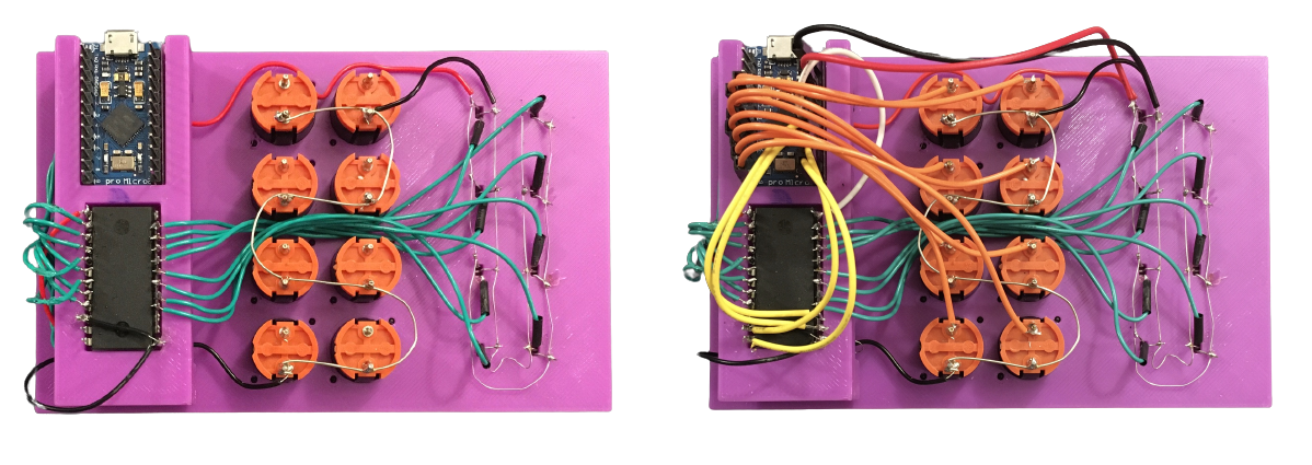
    Next I wired the outputs of the 16 sensors and power to the multiplexer (left below). Finally I connected the pro Micro (right below) to the buttons, multiplexer, and project power.

    Here are all the connections.

    Arduino pro MicroCD4067BE MultiplexerWire ColorOther
    VCC+5VDark OrangeAlso powers the sensors.
    GNDGNDBlackProject Ground
    A0Common Input (Read the channel selected by S0-S3)White
    I/O Pin 2-9Light OrangeButton 1-8
    I/O Pin 15S0 (These four outputs select which of the 16 analog channels to read.)Yellow
    I/O Pin 14S1Yellow
    I/O Pin 16S2Yellow
    I/O Pin 10S3Yellow
    I0 - I15GreenSensors 1-16
    GNDE (This is an inverted chip select pin.)Black

    I wrote a quick and dirty test program and discovered a couple of bad solder joints, but everything seems to be working as expected now. Software time.

  • Building Up The Base

    Michael Gardi09/27/2023 at 21:46 0 comments

    The core of this MacroPad will be built around this 3D printed base.

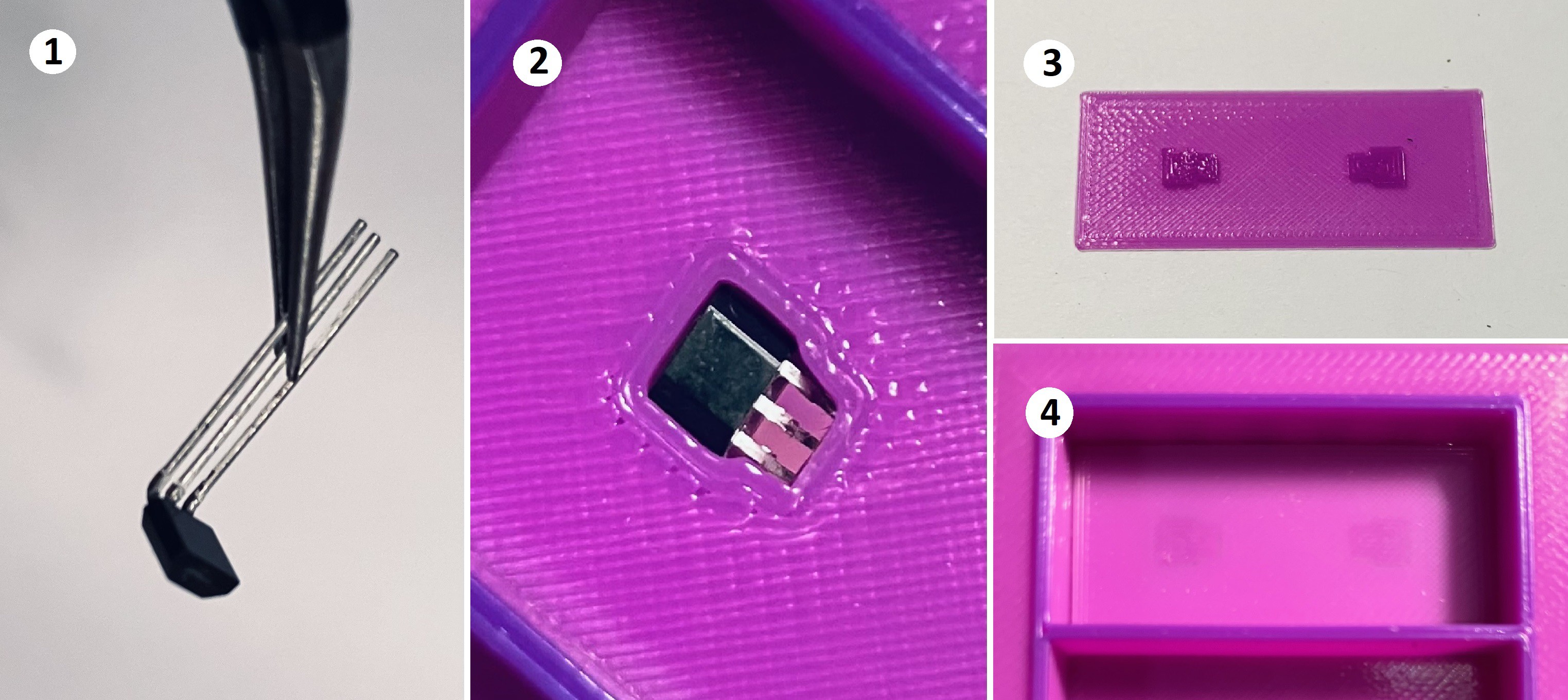
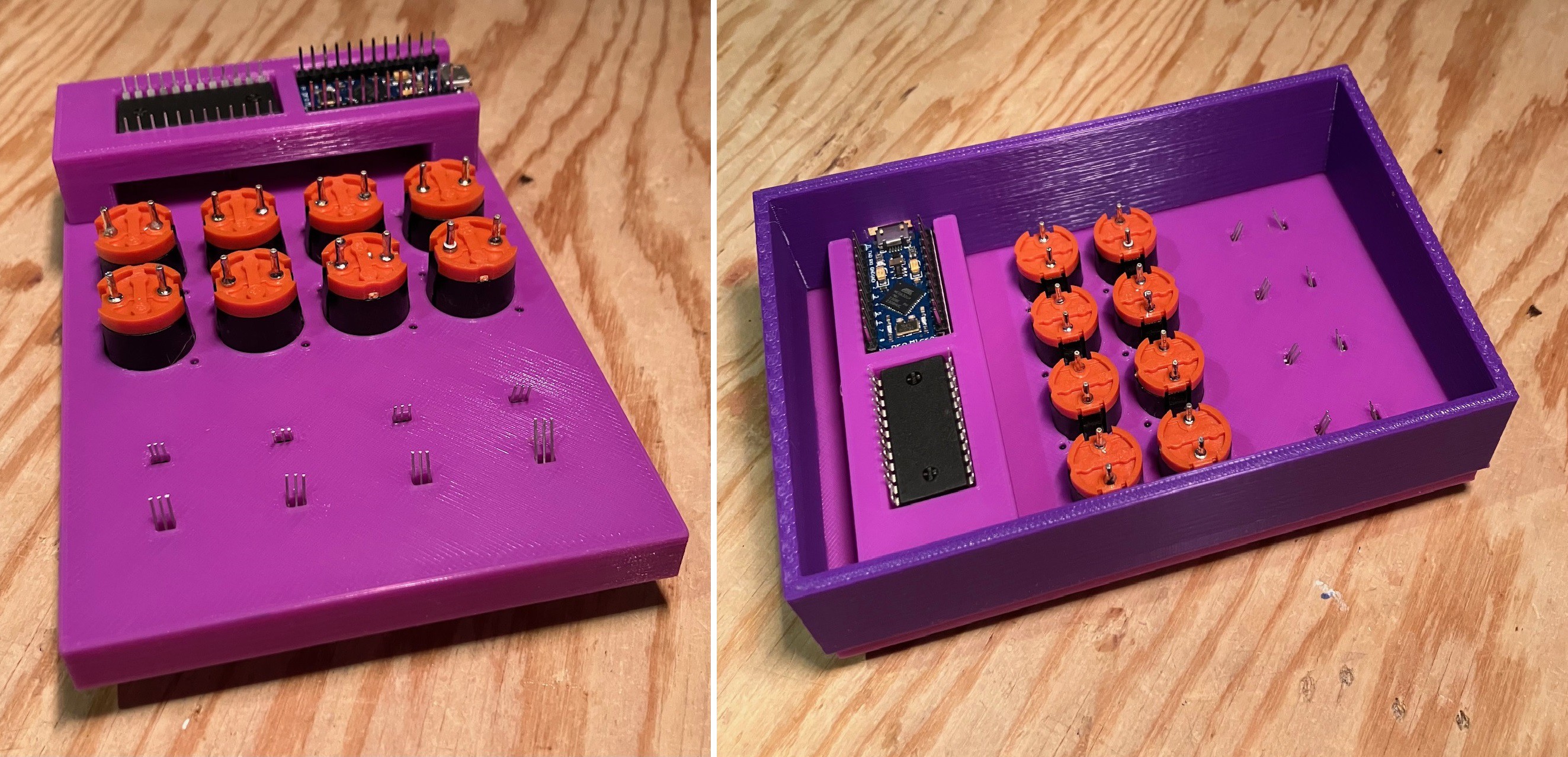
    The center panel has holes to mount the eight Fubata MD-4PCS switches. To the left and right are eight tile slots. You can see at the bottom of each slot two indentations to hold SS49E linear hall effect sensors with holes to pass through the sensor's leads. 

    Adding The Sensors

    1. Start by bending the leads on one of the SS49E linear sensors at about 1 mm from the base towards the flat side of the sensor to about 80 degrees.
    2. Insert the sensor into one of the slot indentations by sliding the leads through the slot's hole and pressing it in place. You should be able to feel it quietly clicking into place.
    3. Add the second sensor to the slot in the same way except that it's oriented 180 degrees from the first. Get one of the slot bottom cover pieces. Notice that there are two raised bumps.
    4. Glue the bottom cover into place making sure that the bumps are facing down. You should apply the glue around the SS49Es without getting any glue on the sensors. (Note: I got burned once when the glue I was using was actually conductive.)

    Repeat for the other slots and sensors.

    Adding The Buttons

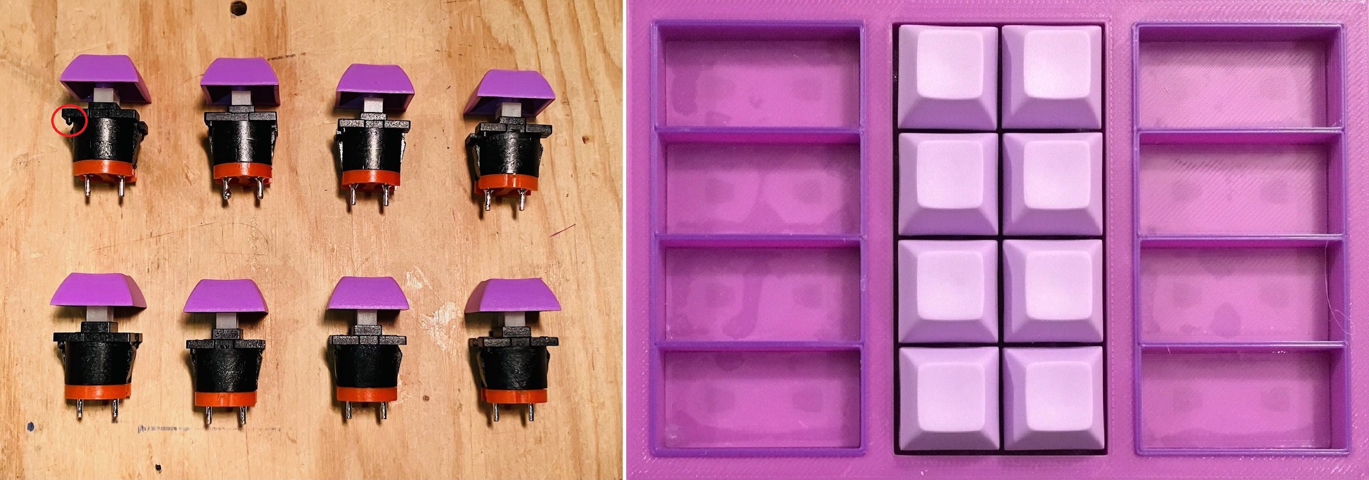
    Here is a look at my Fubata MD-4PCS switches which I'm using because I still have a bunch from some of my retro computer projects. They are nice and clicky as retro keys should be. Snap in the buttons making sure that the two small studs (one of which is circled in red below) align with the holes in the base.

    I love the light lavender keycaps which as I have mentioned inspired the overall aesthetic for this build. 

    On the backside I now have wiring access to the sensors and switches. In addition I designed a frame to hold the pro Micro and the CD4067BE 16-Channel Analog Multiplexer. 

    Here is another look. The pro Micro and multiplexer will be attached with two sided tape.

    Ready to wire.

  • Talking To Tiles

    Michael Gardi09/27/2023 at 01:41 0 comments

    With tile construction set, we now have to calibrate the reading of tiles and establish a "protocol" for mapping tiles to macros.

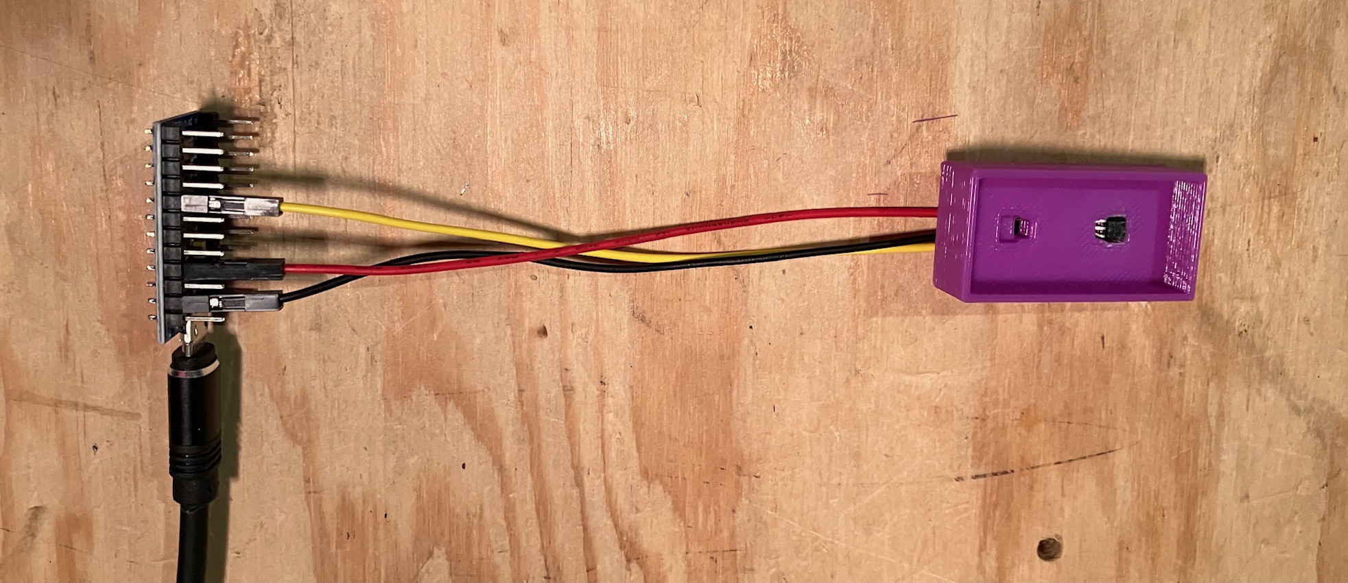
    I'm using the same SS49E Linear Hall Effect Sensor that I did with the TMD-3 project so I know that the Analog To Digital (ADC) default reading from the sensor (with no magnetic field nearby) is the middle of the range. Furthermore a magnet with one polarity will move the reading to higher values while the opposite polarity moves it to a lower values.  So I printed a tile slot and populated it with a single SS49E sensor. The sensor is pressed into a precisely sized and positioned indentation at the bottom of the slot with the leads extending below.

    I wired the sensor to my pro Micro.

    Pro MicroSS49E
    VCC+5V
    GNDGND
    A0OUT

    I wrote a simple sketch to read the sensor.

    /*
      MacroPad Sensor Calibration.
     */
    
    int sensorPin = A0;   // Sensor input pin.
    int sensorValue = 0;  // Sensor value.
    int sensorMid = 0;
    
    void setup() {
      Serial.begin(115200);
      Serial.println("MacroPad Sensor Test!");
      sensorMid = analogRead(sensorPin);
    }
    
    void loop() {
      // Read the value from the sensor.
      sensorValue = analogRead(sensorPin) - sensorMid;
      if (abs(sensorValue) > 20) {
          // Magnet detected.
          Serial.println(sensorValue); 
      }
      delay(1000);
    }
    

    Using this code I established the following table.

    Assigned Number01234567
    Magnet Distance0 mm1 mm2 mm3 mm0 mm1 mm2 mm3 mm
    PolarityNNNNSSSS
    Sensor Reading1801047953-164-114-81-49

    The important thing here is the first and last rows. If the value read from the sensor is "close" (there will always be a little variance between different sensors and tiles) to one of the values in the last row, then that position will be assigned to the number in the first row from the same column. So for instance if the sensor value read is say 50, then the value for that position will be assigned a value of 3

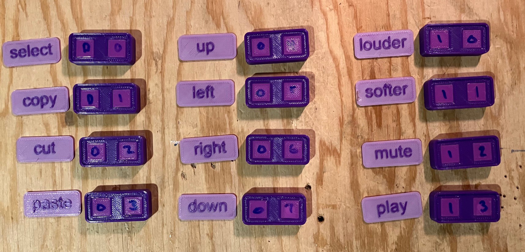
    Remember that each slot has two sensors. When you drop in a tile, the assigned value from the left position will be combined with the assigned value from the right position to form a two digit "key" that will map to a specific macro. Astute readers will realize that each tile will thus have a valid two digit octal number key associated with it. Of course care must be taken to make sure that all tiles have a unique key.

    So here are my first 12 tiles ready to have the top labels attached.

    12 down 52 to go.

  • Making Magic Tiles

    Michael Gardi09/26/2023 at 15:47 0 comments

    OK I know the tiles are not magic, they are magnetic, but despite my advanced years I still find magnetism well, magical.

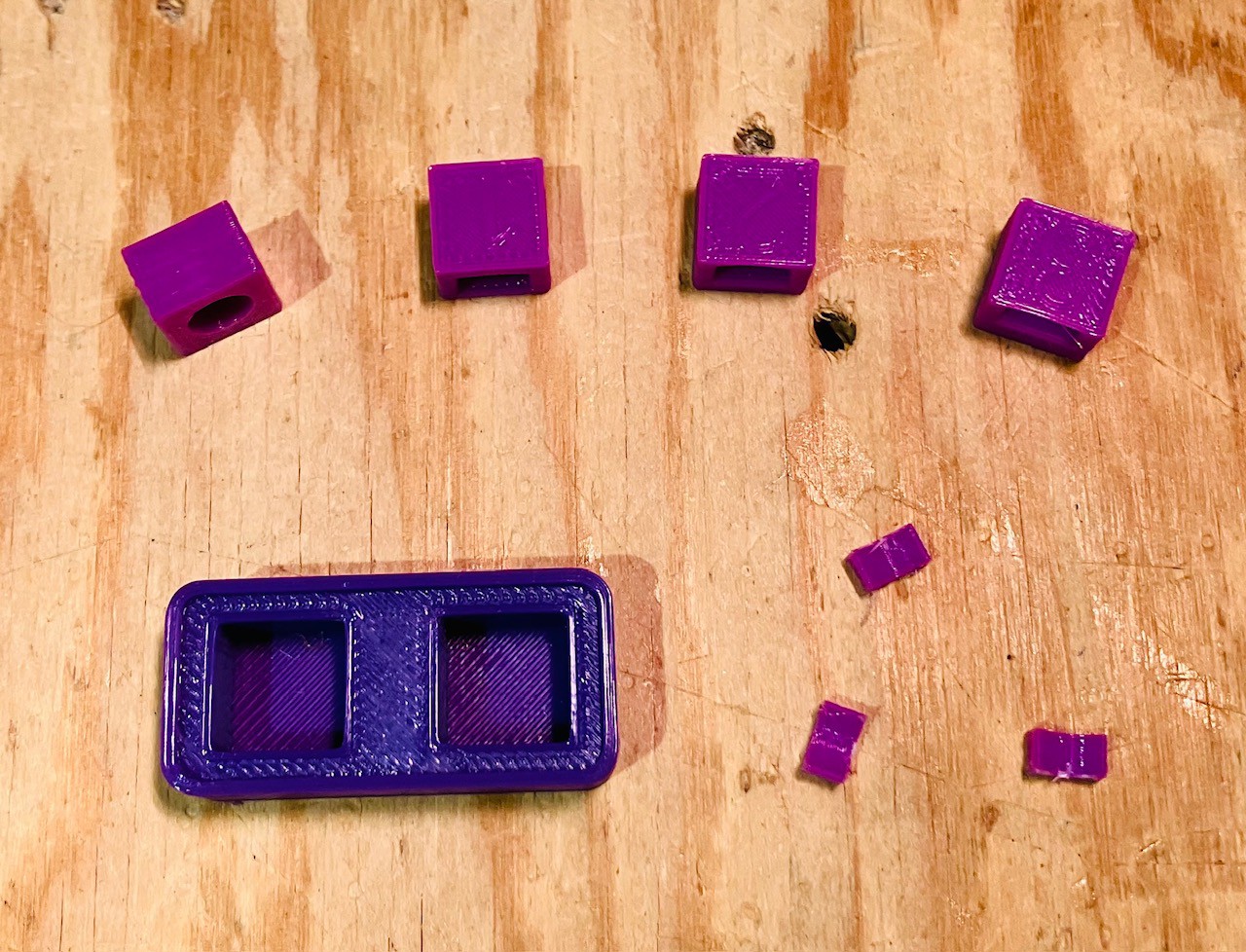
    A tile starts with a base. The base has two square "wells" to hold the magnets. I learned from TMD-3 that with one magnet and a single linear hall effect sensor, given the thickness of a tile as a constraint and the sensitivity of the sensor, you can reliably differentiate between about 8 different tiles. So with two magnets and two sensors I can have 64 unique tiles. You can see the dark violet base below.

    You can also see in this picture four lavender magnet holders. When trying to measure the strength of the magnetic fields consistently between different tiles it's important to set the magnets in the exact same position each time. Each of the four magnet holders positions the magnet at a different distance from the base (where the sensor will be), from 0 mm to 3 mm. Of course we know that the magnetic field strength (magically :-) decreases as distance increases. The linear hall effect sensors are responsive enough to detect these small differences. 

    The voids in the magnet holders are sized to snugly hold two 6 mm diameter x 1.6 mm high neodymium magnetic disks. There are also some wedges to make sure that the magnets inserted from the side are precisely centered over the sensor. Here is a better look at the holders. The numbers help me keep them straight.

    But Mike that's good for only four different tiles. Right, but it turns out that the hall effect sensors I am using can detect the polarity of the magnetic field in addition to its strength. So you can double the number of different tiles recognized to eight by just reversing the polarity of the magnets and using the same four holders. 

    To make a tile simply drop two "loaded" magnet holders into the well and attach a labelled "top" to the tile with a few drops of glue. Of course you will have to keep track of the "values" associated with the magnets used and map them to the specific macro that the label of that tile indicates. More on this later.

View all 8 project logs

Enjoy this project?

Share

Discussions

Michael Gardi wrote 10/16/2023 at 19:20 point

Cool idea. You should easily be able to get 100s (?) of unique resistances and would only require one analog read per tile not two. 

  Are you sure? yes | no

RunnerPack wrote 10/16/2023 at 18:17 point

I thought of a cheaper, simpler, possibly more reliable detection method:

1. Use two magnets per tile.

2. Connect a resistor between the two magnets.

3. Each magnet sticks to a separate metal plate.

4. Measure the resistance between the plates.

For space savings, just make the key and "tile" one, hot-swappable unit.

  Are you sure? yes | no

Michael Gardi wrote 10/16/2023 at 19:23 point

  Are you sure? yes | no

Similar Projects

Does this project spark your interest?

Become a member to follow this project and never miss any updates