-
Case
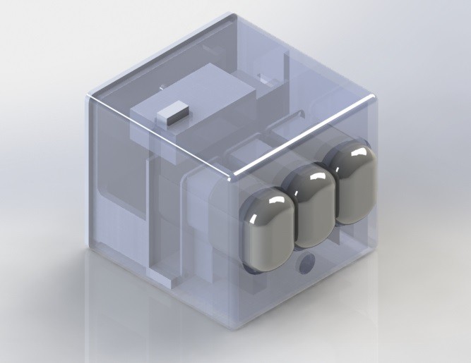
01/13/2017 at 11:55 • 0 commentsNow that the internals are (almost) done, I'd like to make a nice case for this puppy. To the 3DPrinterMobile!
Now, this looks good and all, but as I forgot to bring my calipers, I had to measure everything with a ruler! Even with the wide tolerances I took, the openings will probably be off by a few mm... Eh. Let's get that printed!
![]()
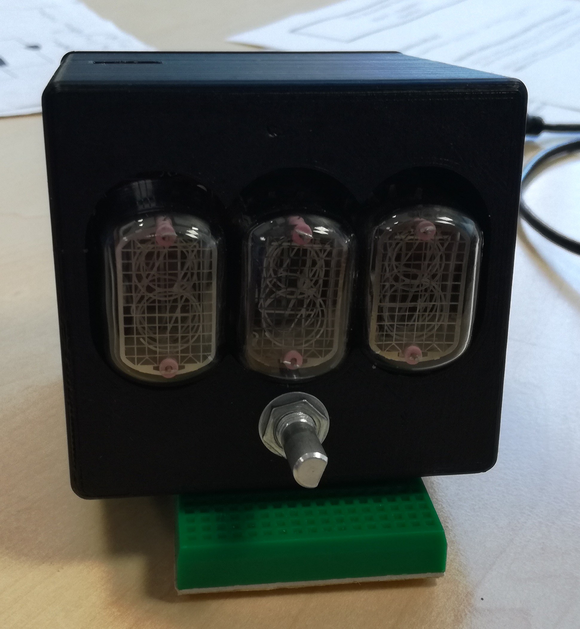
Got lucky here! The board fits perfectly, It's correctly sandwiched between the two halves. The USB port for the Arduino Mini doesn't line up exactly with the opening, neither does the port for the thermometer. I had to slightly trim them.
I think I'll probably leave this project as it is now... The only improvements now will only be software-side: implement the rotary encoder, other sensors, ...
-
Building the controller board
01/06/2017 at 17:11 • 0 commentsThe driver boards are designed as a repeatable way of easily interfacing a Nixie tube with a microcontroller... I have to be able to quickly have a bunch of them available without too much fuss. I won't say the same for this main board; I'm too impatient to design a one-off board, wait three weeks, I want my display NOW!
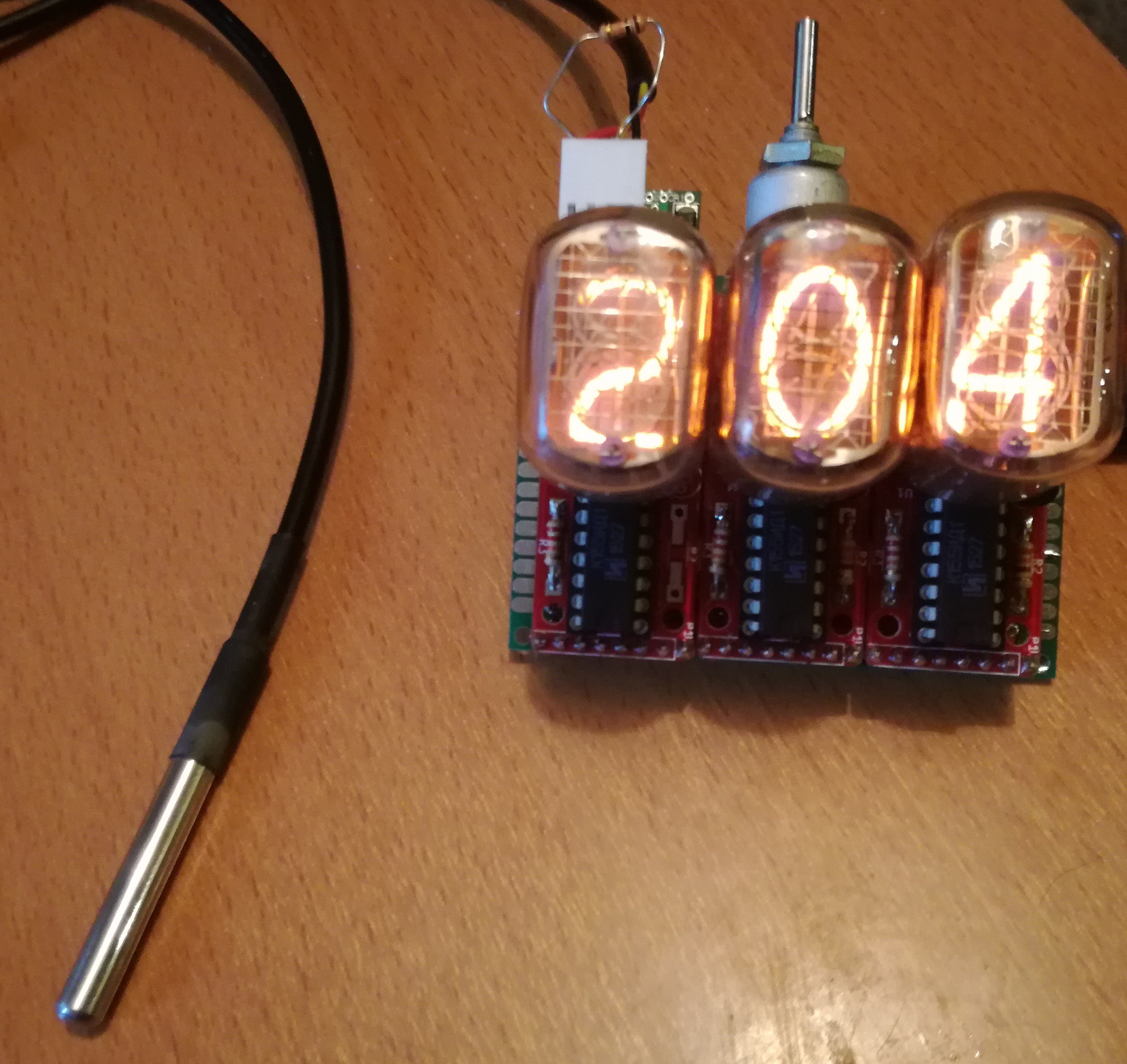
Three Nixie driver boards were used: one without decimal point (with an IN-12A tube), two others with decimal points (with two IN-12B tubes). With those, I'll be able to display values from 0.00 to 9.99 with two decimal digits, 10.0 to 99.0 with one decimal digits, and 100 to 999 without decimal digits. It seems to be the best compromise to me.
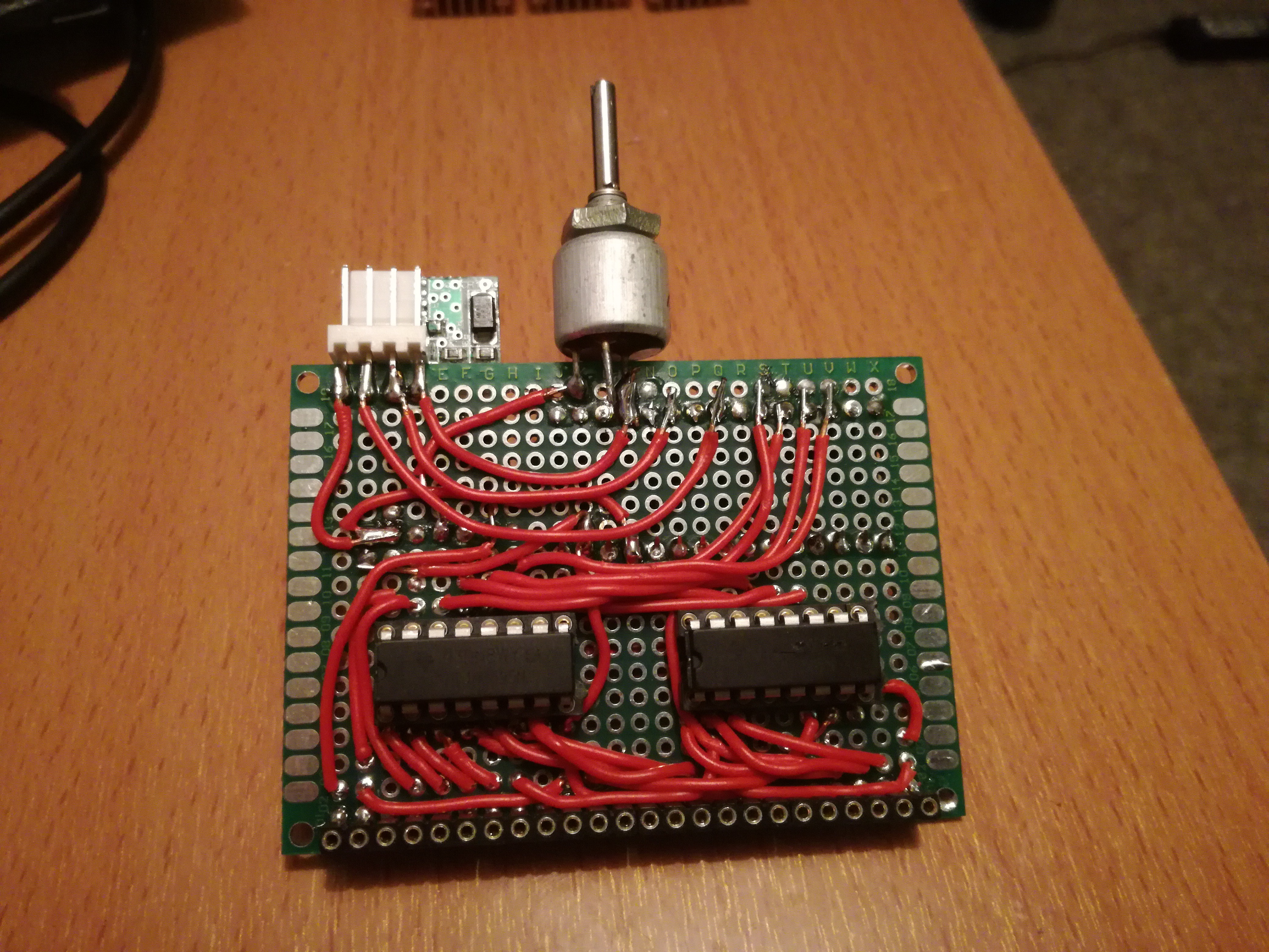
A simple ATMega328 doesn't have enough (or barely enough) pins to directly send signals to the three drivers+the two decimal digits+the sensors... I used two cascading shift registers (74HC595) to reduce pin usage. Queue the big mess of wires.
![]()
The two first digits (i.e. 4 data lines each) were connected to the first shift register, the last one (along with the two decimal points) was connected to the second register. The serial, data, clock and enable line were then connected to the microcontroller.
![]()
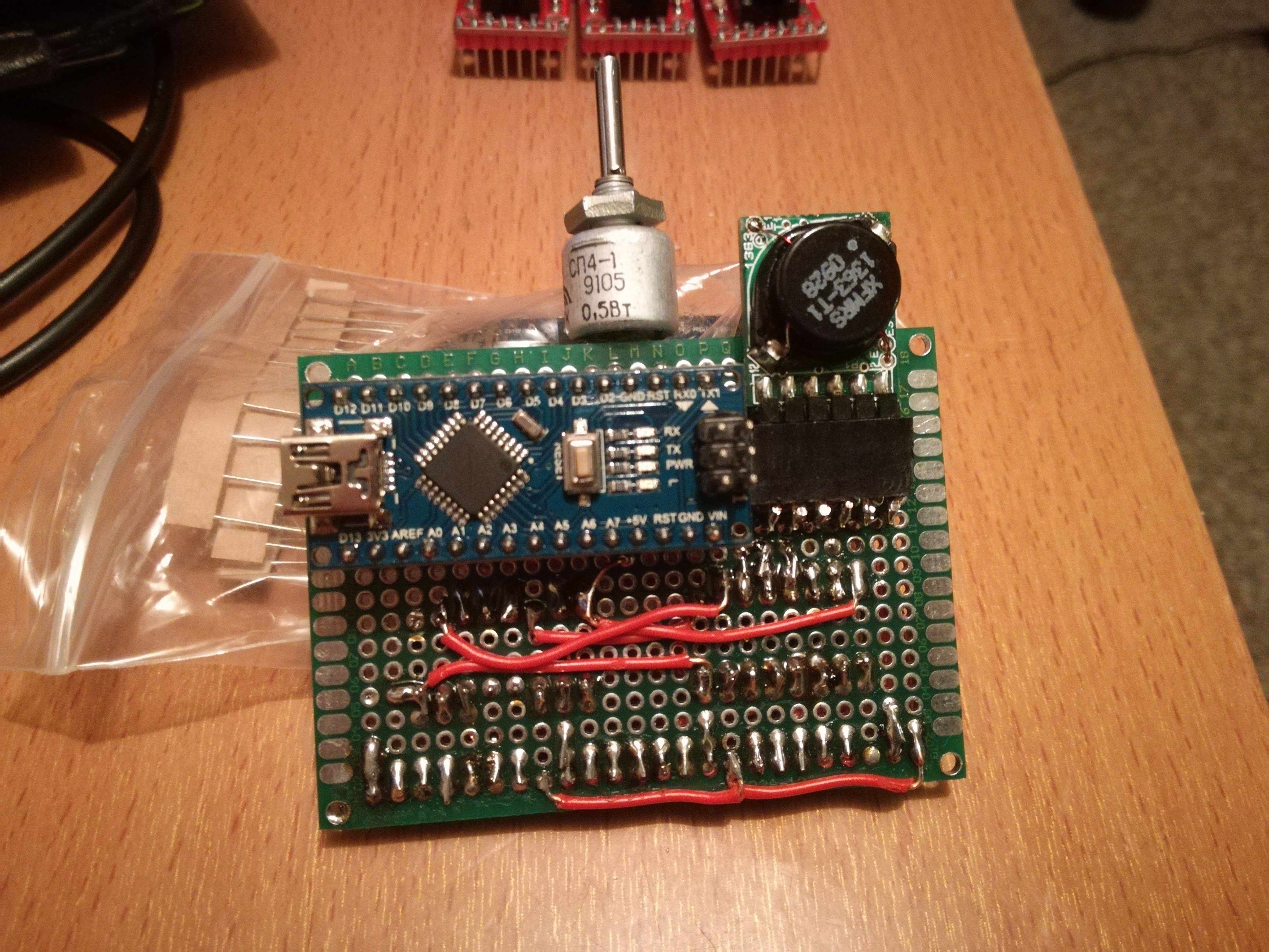
The high voltage power supply (1363 model from Taylor Electronics) is connected on the other side, along with the ATMega328 controller. The potentiometer sets the PSU voltage, and a 4-pin connector allows to connect the sensors (two data lines, 5V and GND).
I first tried a DS1820B temperature sensor... The temperature (in °C) seems to be correctly displayed. For negative values, I made the display blink for 50ms.
![]()
I need to make a case for this!
-
Driver boards arrival, first tests
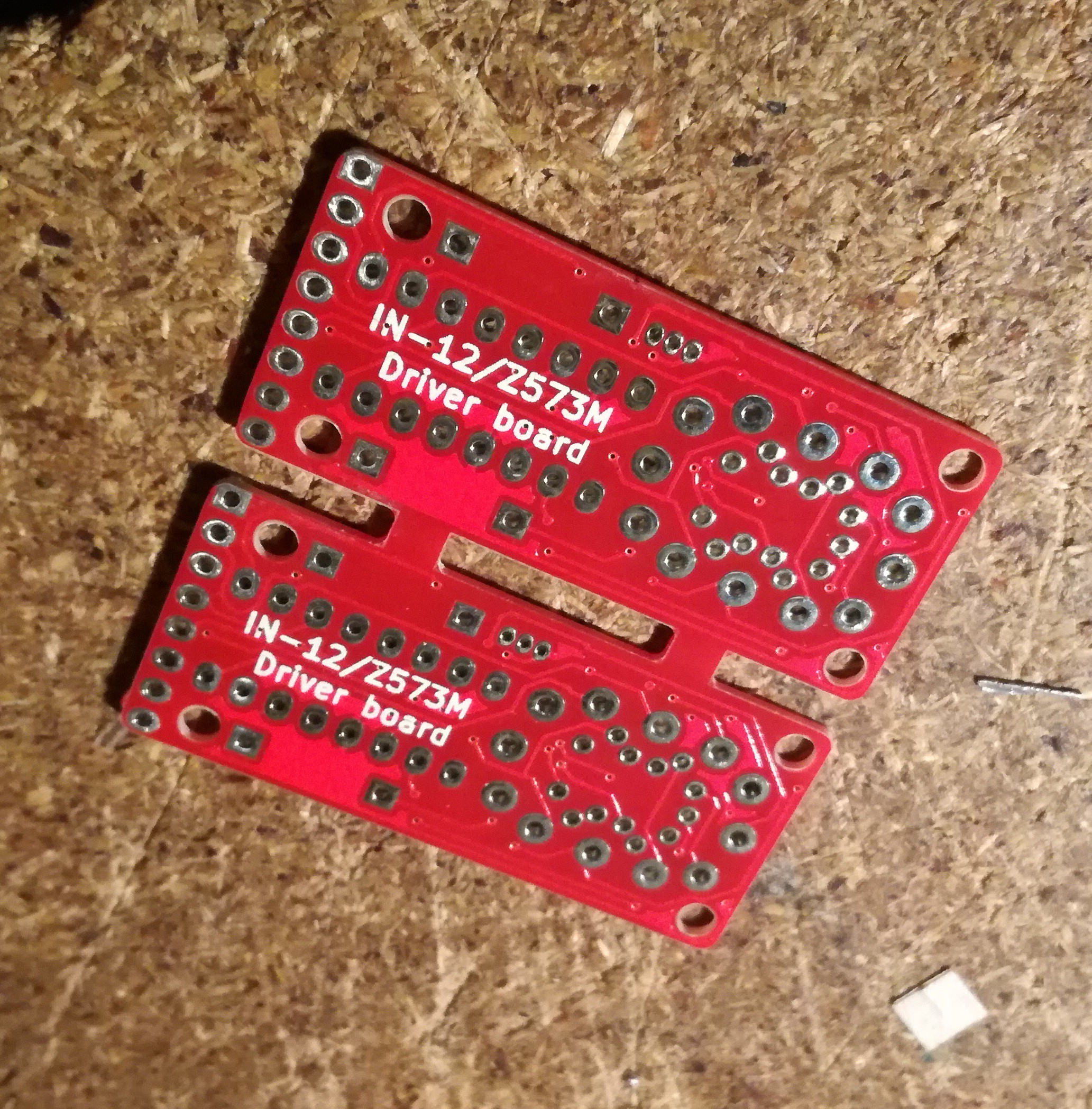
01/06/2017 at 16:45 • 0 comments3 weeks. I never had such a fast delivery time. I received 10 panelized boards, which means 20 boards total!
![]()
I was afraid the grooves weren't gonna be correctly made, but apparently they nailed it! I kept the default red colour, thought it looked nice.
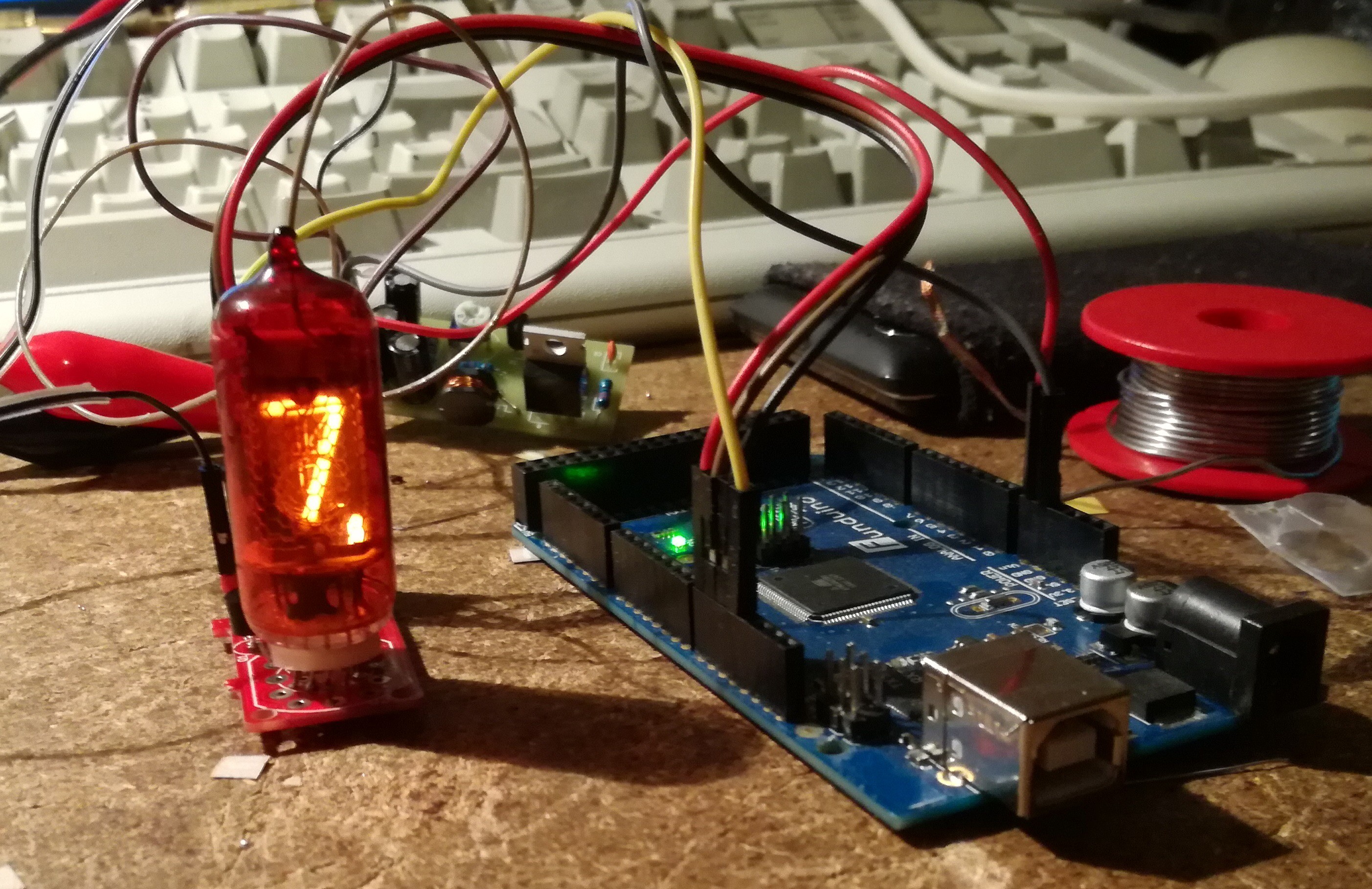
The first test was with a Z573M. Man those tiny leads are a pain to insert into the board... But it worked great on first go! The logic signals came from an Arduino I programmed to scroll through the entire range, while blinking the decimal point.
![]()
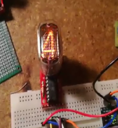
I made three other boards with IN-12 tubes, they worked just as well.
![]()
Off to make something useful with this!
-
Nixie driver board design
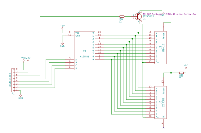
01/06/2017 at 16:22 • 0 commentsThe Nixie tubes are individually controlled by a K155ID1 driver. The driver boards simply contains this chip, an optional HV transistor for the decimal point, a couple of resistors and two footprints:
- One for the IN-12A/B Nixie;
- Another one for the Z573M Nixie.
I chose those two because it was what I had in stock; furthermore (at the time I'm writing this), the IN12 and Z573M are one of the cheapest tubes you can find online.
![Driver board schematic]()
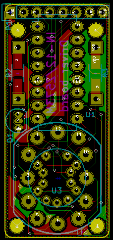
KiCAD was used for the schematic and the PCB.
I tried to cram everything in the smallest board possible, while keeping the possibility of installing either tubes. Particular care was taken in making sure the correct pin sequence was followed for the tubes.
![]()
The boards were sent to dirtypcbs... As they were 20x50mm in size (smaller than the minimum size), I panelized them to get twice as many boards :)
 M.daSilva