Overview
After designing, getting the parts and building this project on October '23, I realized the strong similarites with https://hackaday.io/project/186842-mini-solar-system and, I guess, with many unpublished others.
However I published it here anyway because I think a few peculiarities deserve public interest.
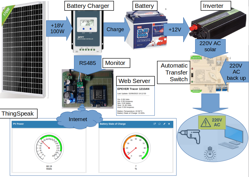
Block diagram
Solar Panel
i bought a nominal 170 W (111 x 77 cm) monocrystalline from Eco-Worthy. At the moment I cannot get more than 105W at noon with full sunshine in October at my 43° 11' Latitude. (I don't know why!).
Price: 85 Euros including shipping
Battery Charger
I bought an EPEVER MPTT 1210AN battery charger because I liked to monitor its working parameters by its RS485 output.
The Instructions say clearly to connect the Inverter to the battery (1) and not to the "user" dedicated output (2) without explaining why ☹️
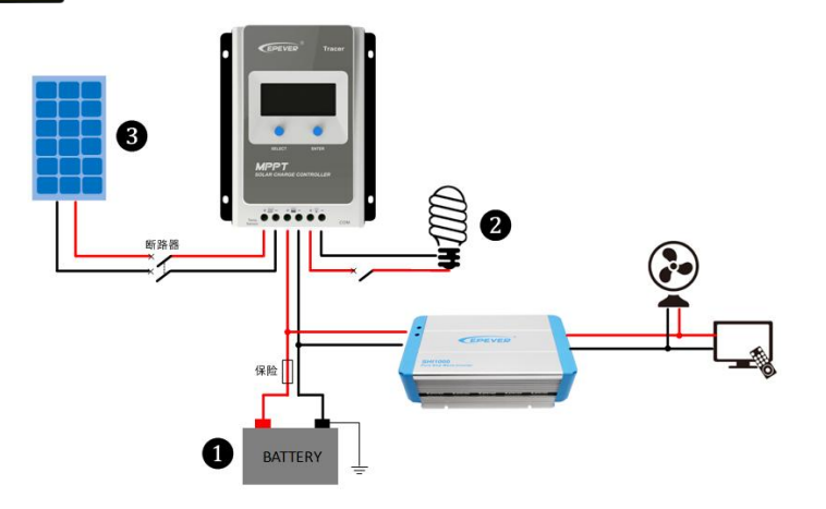
I suppose to have found the reason. EPEVER asks to connect the Inverter to the battery because the "user" output is capable of supplying a maximum of 20A, while an Inverter like the one I adopted could draw 50A (600 W) and more. However, this solution has an issue, at least for me, because my Inverter starts working (generating 220V) when the input voltage rise to 12.2V and stops when it falls below 10.8V. Such a range is too limited and well below the battery operating range, which is 11V to 13.5V. In fact the operating range of the EPEVER "user" output (i.e. when the "user" output is powered) is 11 - 13.5V.
Therefore I decided to add a 100A relay (like the ones for engine starters) powered by the "user" output. In this way I solve also another issue: the inverter draws around 1A when it has no load ☹️. This absorption leads the battery to discharge down to the limit when its BMS disconnects it and, as a consequence, during the night the battery is not operating and the monitor is not supplied.
The relay is driven by the Battery Voltage. See below the Voltage Hysteresis.
Price: 71 Euros including shipping
Voltage Hysteresis
This circuit connects the battery to the Inverter when the battery voltage rises above 13.5V and disconnects when it falls below 10.5V.
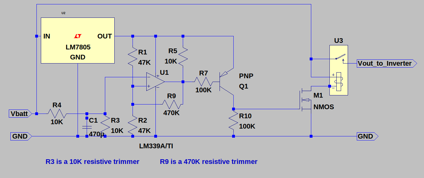
- Adjust R9 to obtain 3 Volts hysteresis (13.5 - 10.5 = 3V)
- Adjiust R3 to obtain max=13.5V min=10.5V
- (repeat if necessary)
Battery
I opted for a LiFePO4 12V 50Ah battery with internal BMS from TimeUSB.
Price: 155 Euros including shipping
Inverter
I found a Green Cell 500W pure sinusoidal inverter
The case remains pretty cool (<30° centigrade) while supplying 100-150 Watts, even if the noisy fan starts frequently. For this reason, I changed the original 12V 0.22A fan with a less noisy (and less powerful 😀) 12V 0.1A fan, scavenged from an old PC.
Price: 83 Euros including shipping
Automatic Transfer Switch
Until now, I didn't know the existence of such kind of device. The Jadeshay 2P 100A 220V I bought is nothing more than a very fast (less than 20 milliseconds) stepper relay but it is fast enough to switch almost seamlessly to the AC mains when the voltage from the inverter goes down and viceversa when the Inverter comes back to operate again. The supplied PC's I tested have no problem, while my 32" Samsung TV have a very short screen blanking (the screen becomes black and reappear in half a second).
I see two issues:
- the relay sounds a very noisy "clack", which I attenuated inserting the ATS in a 1.5 cm thick polistirene box.
- its electrical life is guaranteed for 2000 times (see Instructions) i.e. switching 6 times a day it should live less than an year ☹. I'll try to study a mosfet/TRIAC alternative or adopt a solution like this TRIAC based transfer switch.
Price: 35 Euros including shipping
Monitor
I built this circuit with an ESP32, an RS485 board and a...
Read more » Guido
Guido

 Gabor Futo

 Bryan Williams
 Hulk
Hulk
 akbarhash
Thank you Dan! That ATS is working very well. Anyway, beside the strong noise "clack" when it switches, I found another issue: its electrical life is guaranteed for 2000 times i.e. switching 6 times a day it should live less than an year ☹. I'll try to study a mosfet alternative!