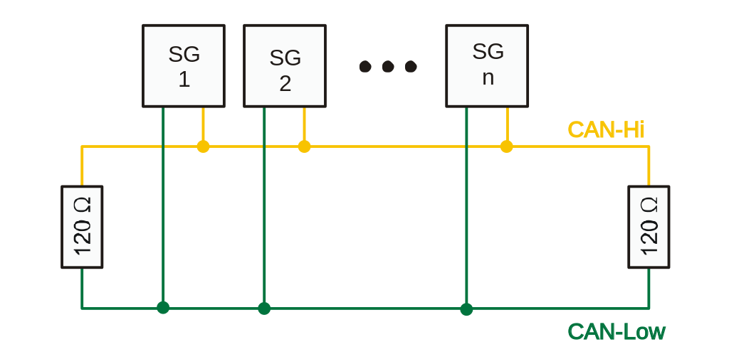
The entire design is built around a shared bus, into which multiple modules, interfaces and screens are plugged in. With various sensors asynchronously producing data, a one-to-many bus that supports message broadcasting is required. This leaves us with some options...
- Ethernet
- I2C bus (in multi-master mode)
- Wireless transceivers
- Custom bus with collision avoidance rules
- CAN bus
Ethernet tends to be a bit too expensive for simple modules, and requires a bulky Ethernet switch. I2C is susceptible to electrically noisy environments, requires a master node to poll slave nodes, and the data rates are quite low. Wireless transceivers are usually not full-duplex and become unreliable when there are too many transmitters and packet collisions occur.
Initially I ran UART over the CAN physical layer (saving some cost and overcoming the maximum 8-byte CAN payload limit), and added some arbitration rules to the protocol. This required some assembly optimisation to check for collisions after each bit transmission, but worked quite well. With the number of sensors increasing, I started to feel a bit uneasy about the reliability of this implementation though.
Hence, the CAN bus was chosen. It is robust (differential pair), features automatic message arbitration (packet collisions are impossible), and is used widely in the aerospace and automotive industries. The can bus consists of a CAN_HI and a CAN_LO differential pair, which is terminated (HI and LO pins connected together with 120 Ohm resistors) on each end of the bus. When no node is driving the bus, the resistors pull the HI and LO lines together and the bus is a high-impedance "recessive state" (logical 1). During a "dominant state" (logical 0), one or more nodes drive the HI line towards +5V and the LO line towards 0V.
(Image from Wikipedia)

Messages are sent out on the bus with a unique CAN-ID, which identifies the message and also acts as a priority. After each bit is sent, the bus is checked for a potential collision by the CAN controller. When multiple nodes attempt to simultaneously transmit, the node with the lower CAN-ID (first dominant bit in the ID) continues transmitting, while the other node back's off and re-transmits at a later stage.
(Image from Wikipedia)
 One disadvantage of the CAN-bus is the small message size: an 11 or 29-bit CAN ID, and 0-8 data bytes. Yes, a maximum payload length of 8 bytes!!! Luckily most sensor values that are broadcast periodically (and make up the majority of bus traffic) can be represented with a single precision floating point (4 bytes).
 Rene
Rene
Discussions
Become a Hackaday.io Member
Create an account to leave a comment. Already have an account? Log In.