The way to get started making is by tearing something apart!
Using some small scissors or razor knife, remove the top seam of the candy bucket lining as much as needed to stick your hand in and move around freely. You'll be placing components and running wire between the linings to hide away all the smarts!
2
Create an access point at the bottom of the bucket
This is where the wires from the inner lining will reach the battery and Raspberry Pi.
The picture above shows where the bottom tear is placed to fit the wires that will be passed through.
3
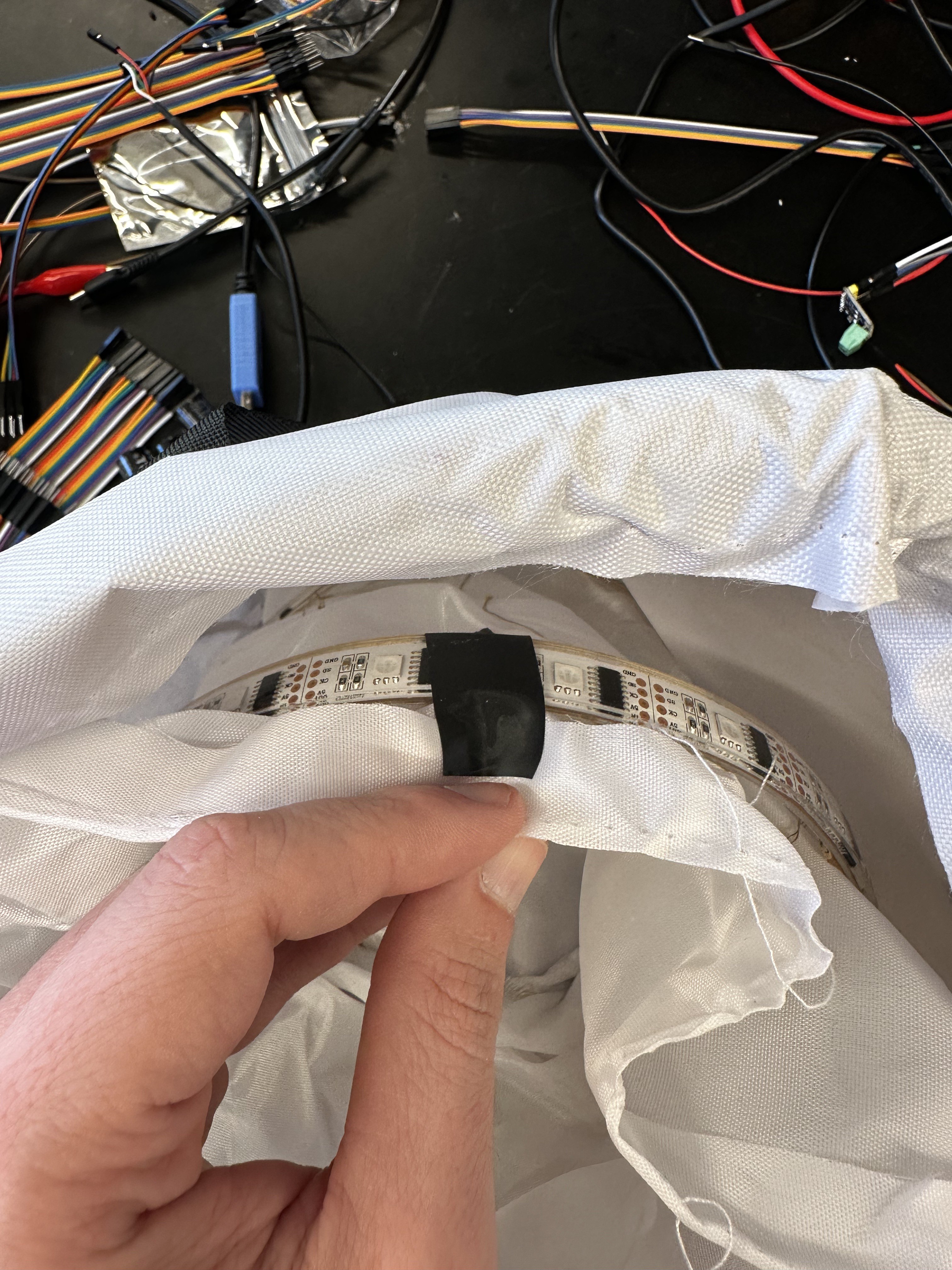
Place the RGB light strip
Electrical tape is a great resource.
The light strip may have some paper backing that can be peeled off so hot glue can be applied to the strip. That will hold it in place within the lining of the bucket. Adding some electrical tape as extra measure will ensure it stays put while continuing to maneuver inside. Make sure the end of the strip with male header pins runs through the bottom access point of the bucket.
4
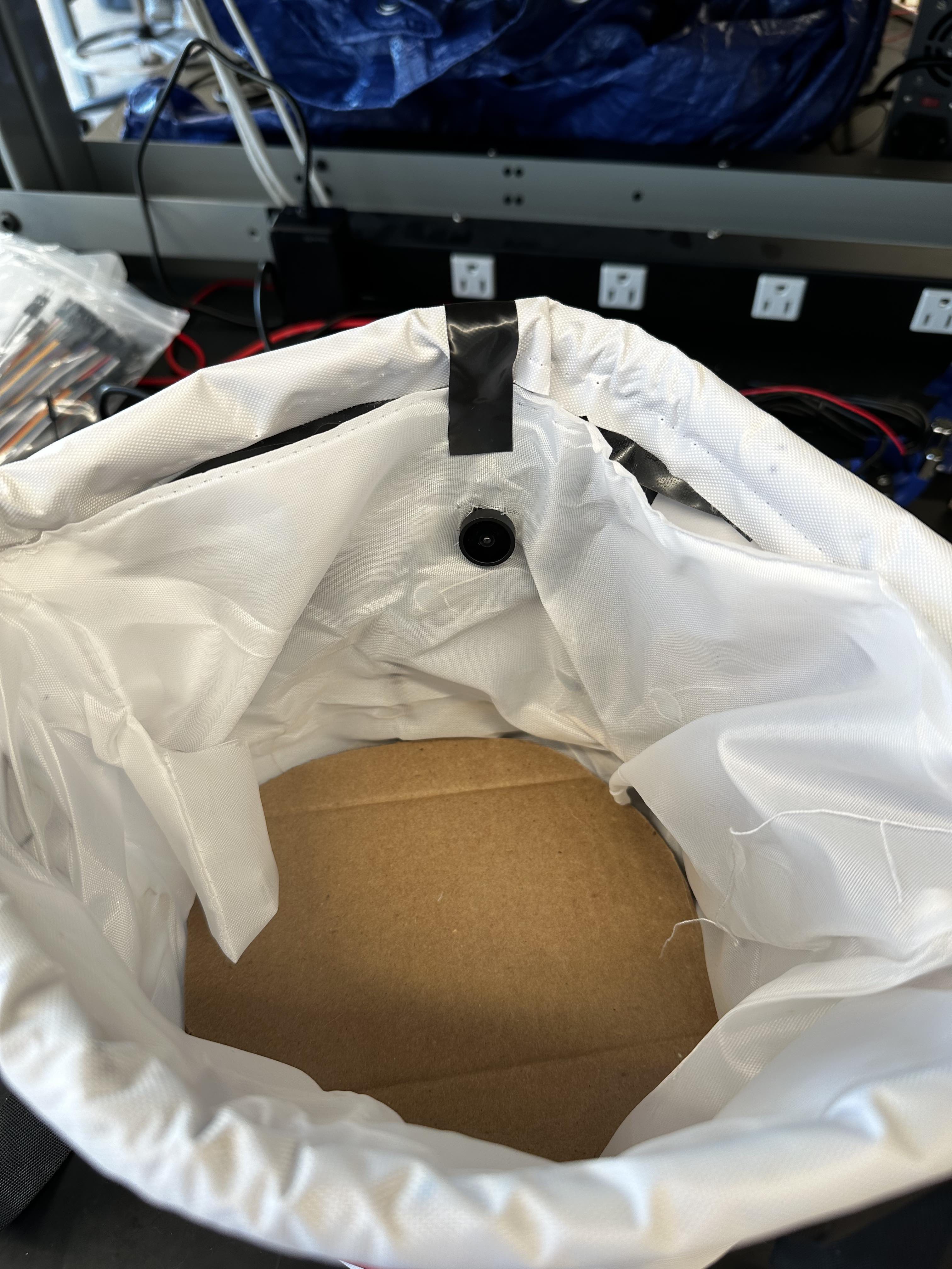
Place the camera
Cut a hole in the lining about a third of the way from the top of the bucket for a snug fit of the camera lens. Use more electrical tape to keep it in place before you're ready to hot glue the back of the camera to the outer lining when closing the whole thing up in a later step. Run the USB cable connected to the camera control board down to the hole in the bottom lining.
5
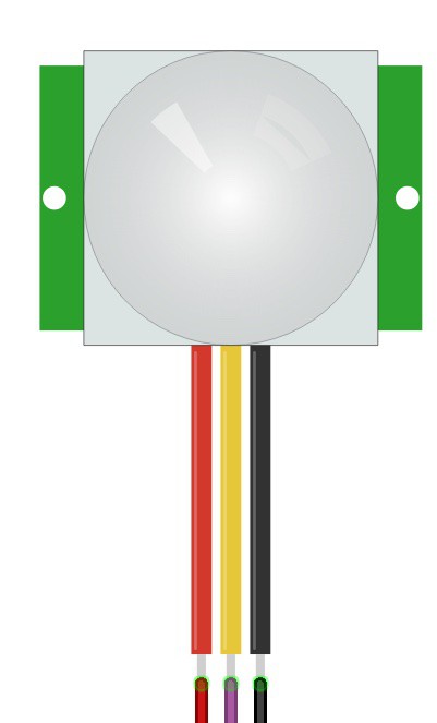
Place the mini PIR
For the mini PIR, I printed a housing to hide it away a little bit and keep the sensor focused on the inside of the bag. It can be mounted anywhere around the rim of the bucket, but I found about 45 degrees from the camera was good to trigger it just before the candy reaches the front of the camera.
Run jumper wire from the PIR to the opening at the bottom of the inner lining. Tape the three wires (power, data, ground) together to make it easier to push through the lining and keep it organized before connecting to the Pi in a later step.
6
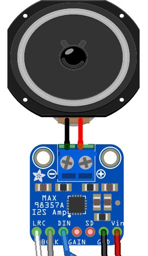
Place the speaker
The speaker should be wired to the screw terminals on the I2S amp breakout board using a small screwdriver, tight enough to make sure they stay in place. Connect jumper wires to the bottom pin headers on the board (Left/Right Clock, Bit Clock, Data In, Ground, and Power) and place those components anywhere you'd like on the inside of the lining. The speaker is loud enough to be heard from within the lining, so it can be placed on the bottom or taped somewhere higher up. Run the jumper wires through the bottom hole of the bucket for connecting to the Pi later. Tape them together to make it easier to keep organized and push through the lining.
7
Place the switches
With two SPDT swtiches, connect two jumper wires to each: one in the middle pin and one to the right pin. The middle pin will eventually be connected to the battery and the right pin will connect to either the Pi or the RGB light strip. Place the switches near the existing fabric pocket holding the button for the string lights within the bucket (not related to the RGB light strip). There should be an existing hole to run the switch wires through to the bottom of the bucket, otherwise make one using some scissors or a razor knife.
8
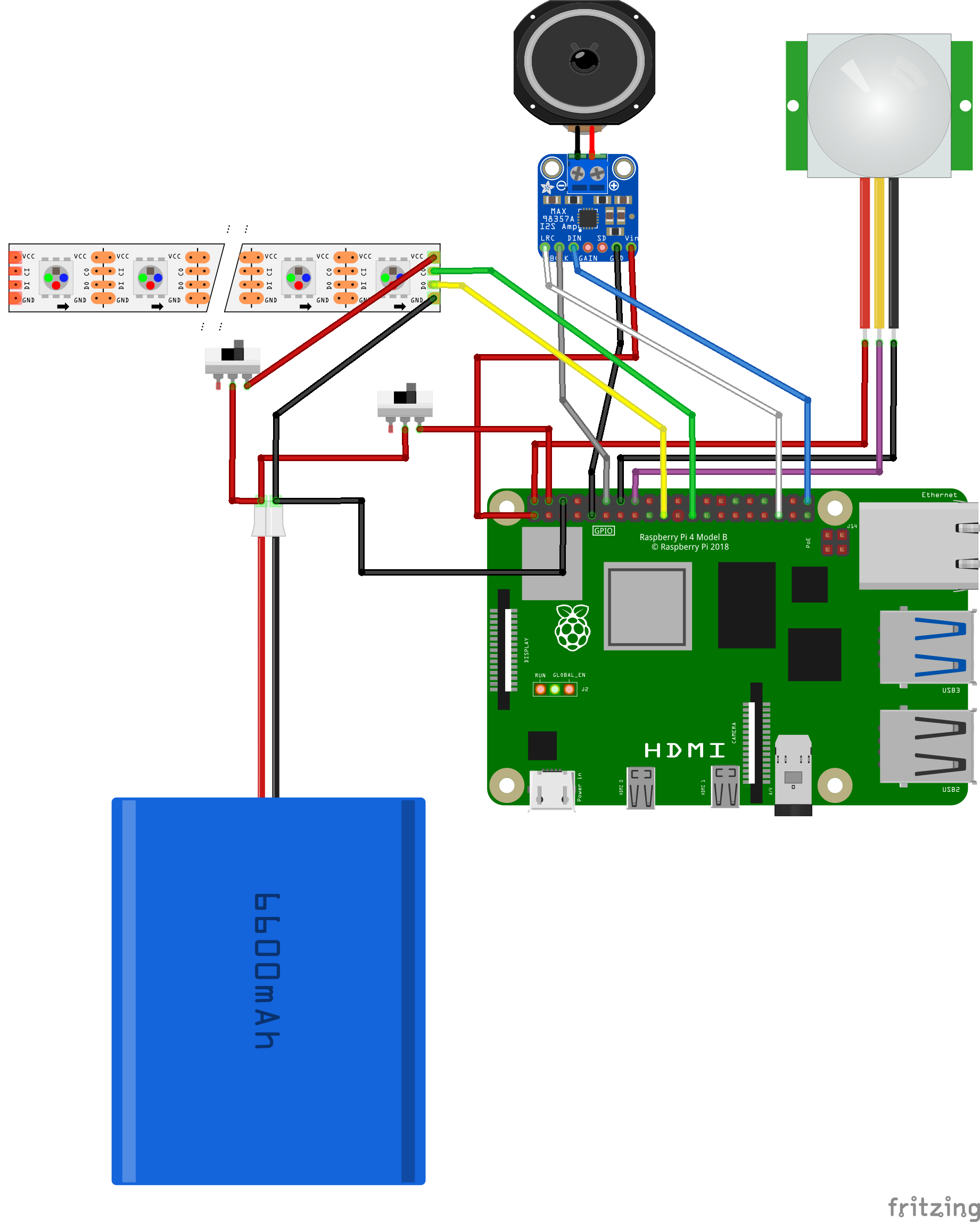
Wire up the Pi, light strip, and battery
After placing the Pi and the battery on the bottom of the bag, connect the jumper wires for all the hardware components. Starting from the top of the pins on the Pi (use this diagram] to follow along if you're unfamiliar with the pinout):
Pin 1 (3v3 Power) <-> Power wire for the I2S amp breakout Pin 2 (5V Power) <-> Power wire for the mini PIR Pin 4 (5V Power) <-> The right pin jumper wire for one of the SPDT switches Pin 6 (Ground) <-> Common ground wire for the battery Pin 9 (Ground) <-> Ground wire for the I2S amp breakout Pin 12 (PCM CLK) <-> Bit Clock (BCLK) wire for the I2S amp breakout Pin 14 (Ground) <-> Ground Wire for the mini PIR Pin 16 (GPIO23) <-> Data wire for the mini PIR Pin 19 (SPI MOSI) <-> Data header pin on the RGB strip Pin 23 (SPI SCLK) <-> Clock header pin on the RGB strip Pin 35 (PCM FS) <-> Left/Right Clock (LRCLK) wire for the I2S amp breakout Pin 40 (PCM DOUT) <-> Data In (DIN) wire for the I2S amp breakout
The right pin wire for the other SPDT switch should be connected to the power header pin on the RGB light strip and the ground on the strip connected to the common ground on the battery.
The middle pin wire on both switches should be connected to the power wire/connector on the battery.
Try flipping the switches to ensure power is running to the RGB strip and the PI correctly. If nothing happens, toggle the switch back the original position before attempting to debug any issues.
9
Set up the Raspberry Pi
With all the hardware components in place, you can start working on the software piece. Although this project uses a Raspberry Pi 4, any single board computer (SBC) that supports general purpose input/output (GPIO) with PCM/I2S pins and runs 64 bit Linux should be able to work as well. Having wireless network (Wi-Fi) is handy for iterating on the software, it is not necessary when using the completed project out in the world. I chose DietPi as the operating system for the Pi because it is very minimal while providing a nice command-line user experience to configure various parts of the system; it also supports many SBCs, so the instructions will stay largely the same.
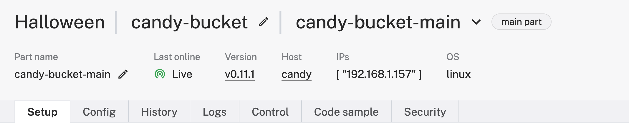
Viam is being used on this project to easily configure all of our hardware, train the machine learning model, and monitor the project for any issues along the way. You can connect the Pi to the Viam platform by installing `viam-server` onto the device following the Viam documentation. Once you've followed all those steps, you should have created a new robot in the Viam app and see it live:
I called my robot "candy-bucket" in a location called "Halloween", but you can name it whatever you like.
 Nick Hehr


 The speaker should be wired to the screw terminals on the


Discussions
Become a Hackaday.io Member
Create an account to leave a comment. Already have an account? Log In.