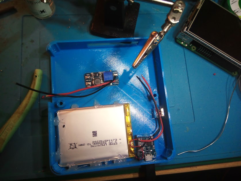
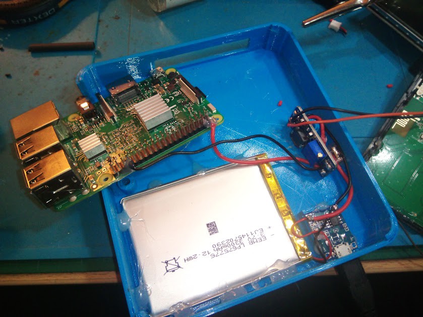
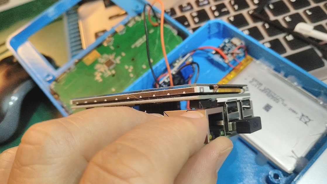
Connect to pins 5V and GND in GPIO). Hold the connections with some glue. Adjust the dcdc Vout to 5V BEFORE TO CONNECT THE RASPI.
4
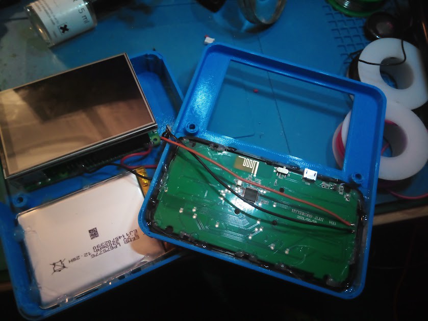
Solder the BT keyboard.
First of all cut the wire of little keyboard battery (only 150mAh). Glue the pieces of the keyboard without its bottom. Solder to 3300mAh in the dcdc DCIN connectors.
5
Glue the little piece to the screen (not to the Raspi).
This adjust the level between Raspi and display. This piece is included in the stl bezel file.
6
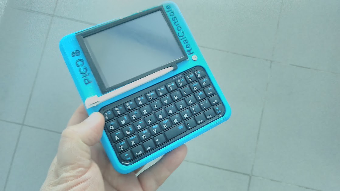
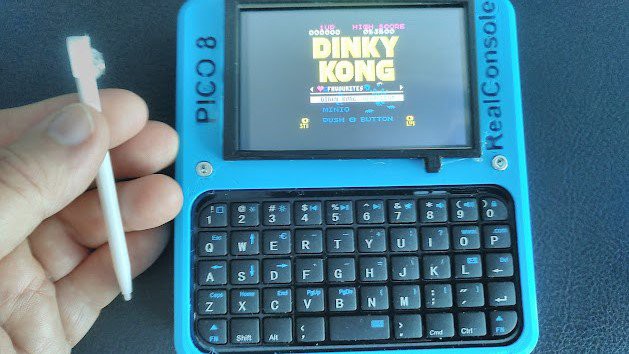
Join the top and bottom with 2xM3 25mm nuts&bolts.
The screen must fit in the upper rectangle. After that, glue the bezel. Glue a little magnet in the top of the stick and test if holds correctly in the bezel.
 Victor Barahona
Discussions
Become a Hackaday.io Member
Create an account to leave a comment. Already have an account? Log In.