I got approached by PCBway who wanted to sponsor a batch of assembled prototypes.
It was a rather significant amount, so thank you again! PCBWay went out of their way to sponsor it, way to go!
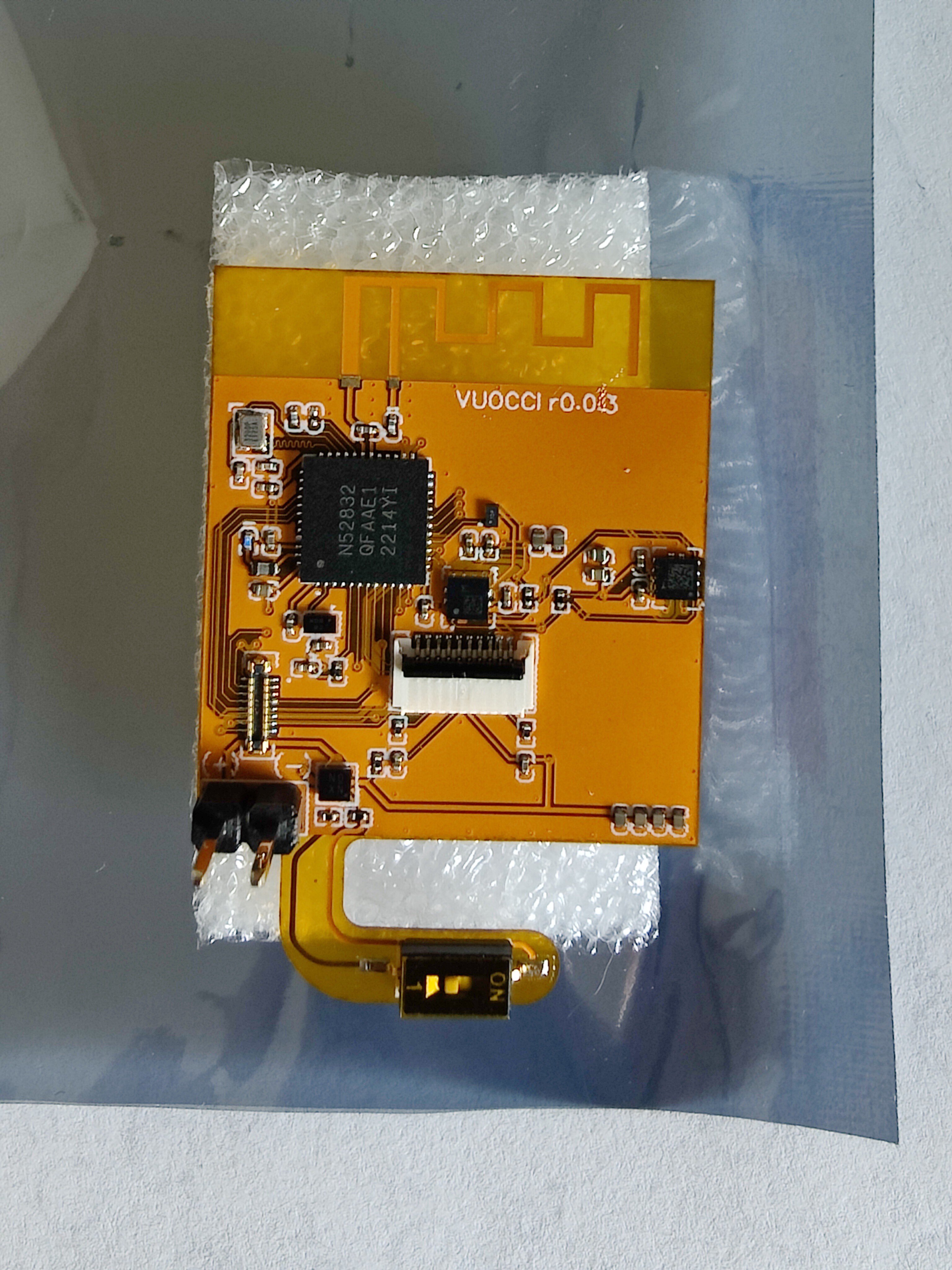
PCBs have just arrived from PCBway, many thanks for supporting this project by sponsoring the PCB's. They have come out looking great, everything is very sharp and the finish is good. Their customer service was very helpful and responsive which was great.
The board worked as soon as I plugged it in. So far I haven't tested all sensors, that will come later.,
Other then that I don't really have much else to report, everything works and its been a great success, I couldn't have hoped for a better outcome so far. Now I'm just back to writing firmware which is going to take forever for me. If someone has many of hours of free time on their hands good, I don't. Thanks again to PCBway for supplying pcbs for this project, I do really appreciate it.
The PCBs are rather costly due to being fully SMD flex-PCB, which is a really challenging process.
Attached is a macro of the flex PCB.
One good thing about PCBWay is that they will source all components for you, you don't have to rely on pre-sourced in-stock components and separately buy them, as with other PCB manufacturing outfits. Also, my PCBs arrived sealed in antistatic bags, which was a nice touch.
One last thing, PCB Way will send you pictures of the assembled product before shipping, for you to visually check the assembly. This is very helpful if you know certain component orientation is tricky, such as photodiodes, diodes, or other small polar components. I've had cases in the past where some component were rotated incorrectly and seeing a picture before shipping helped.
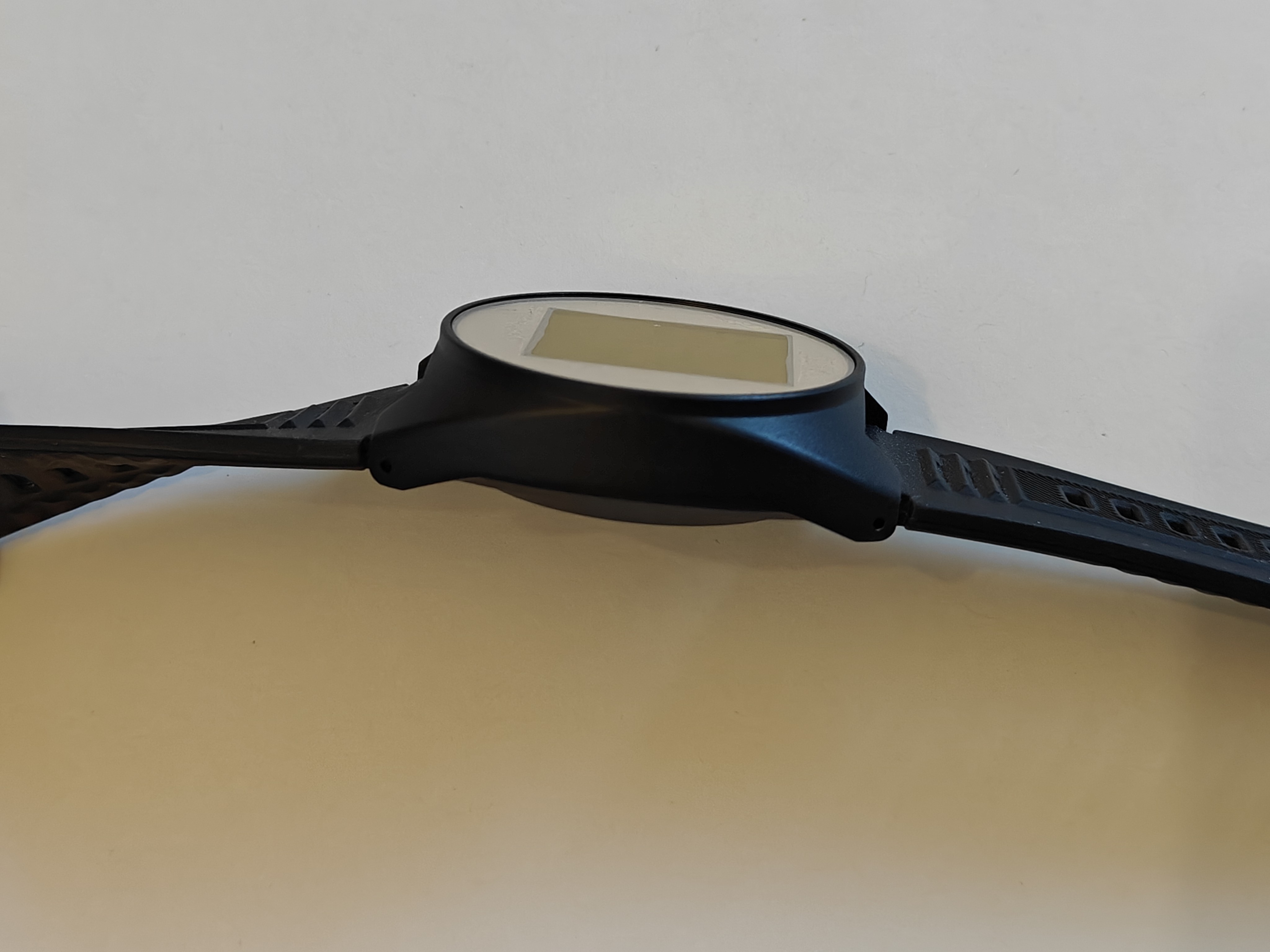
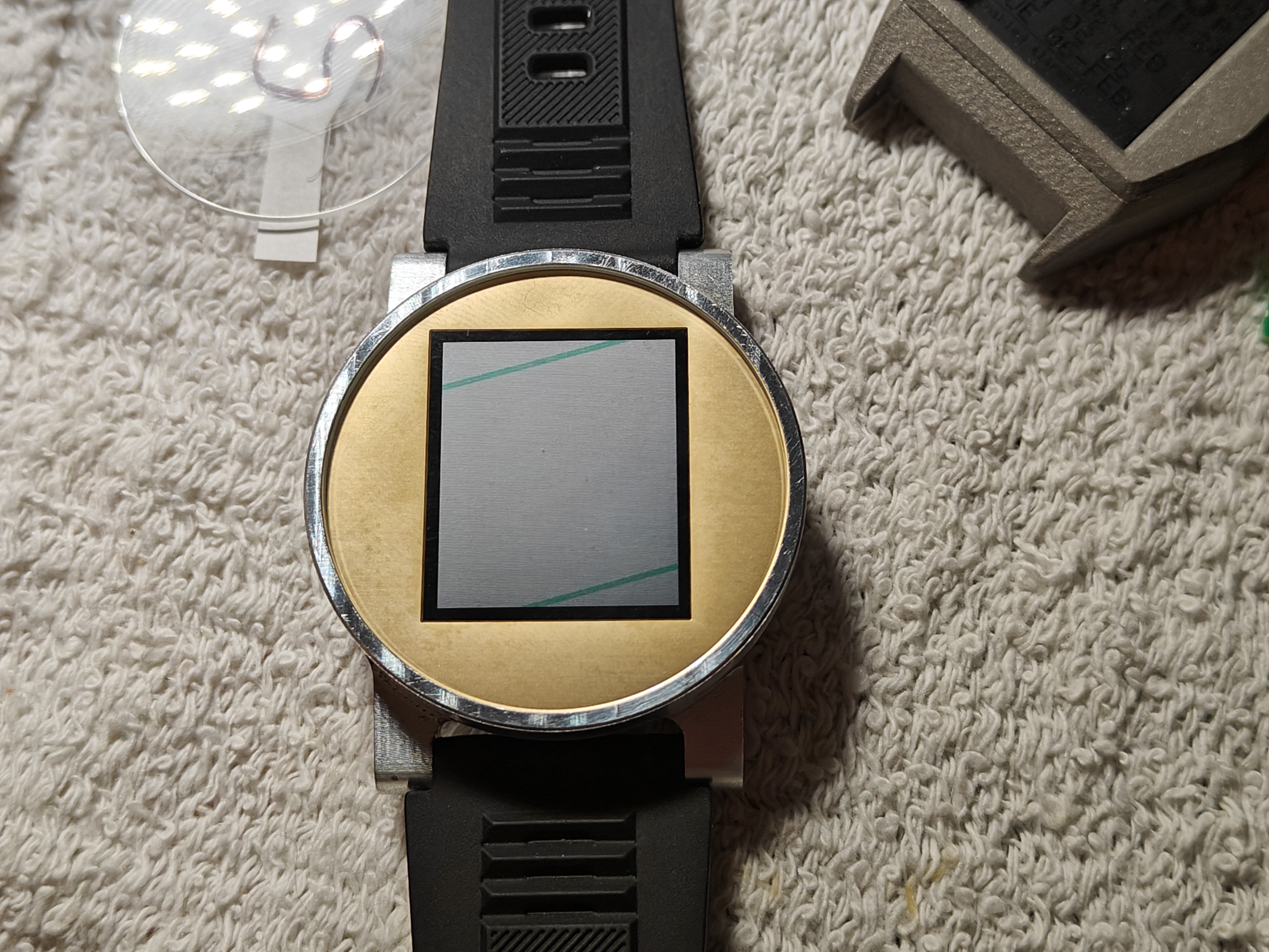
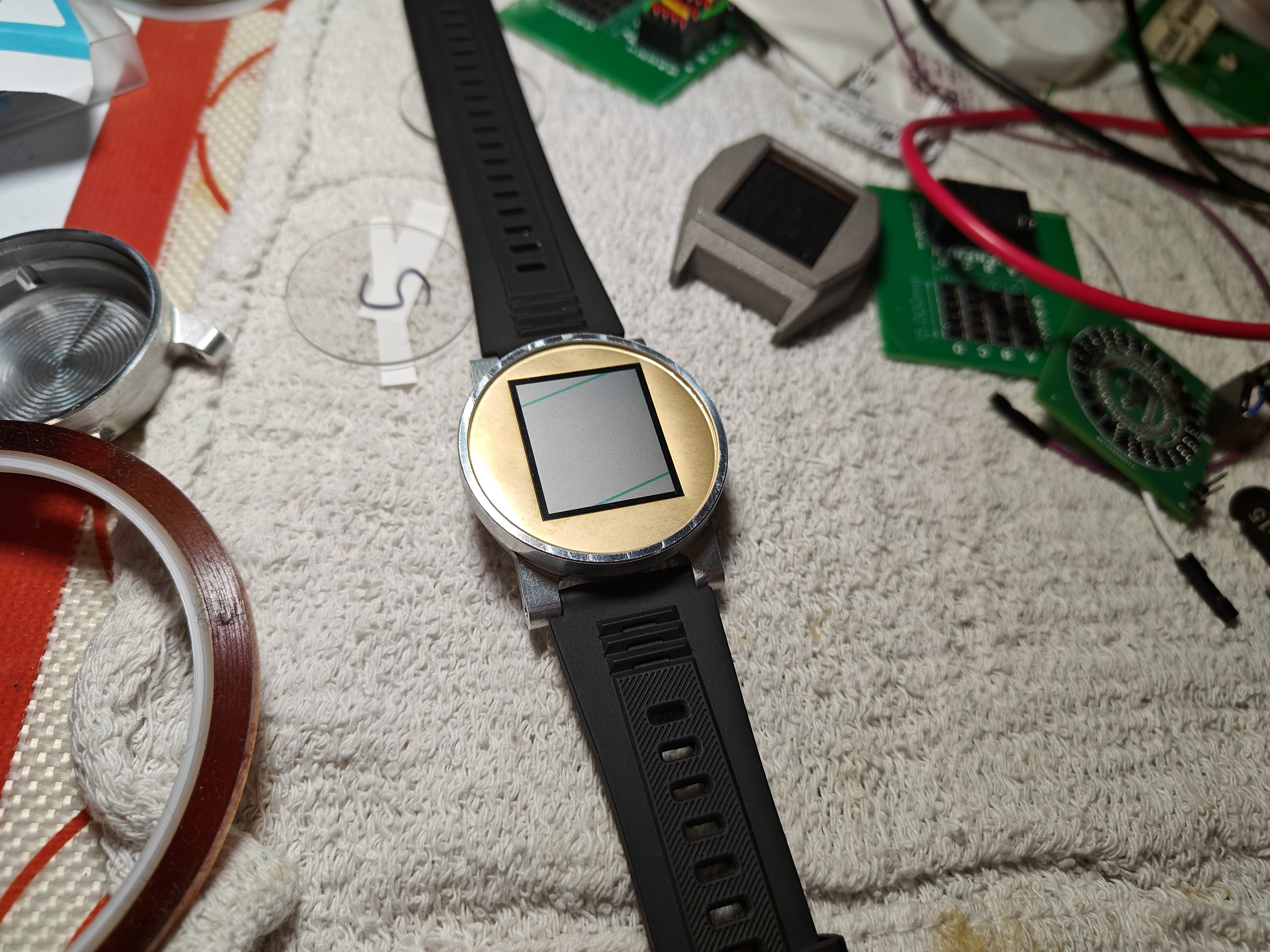
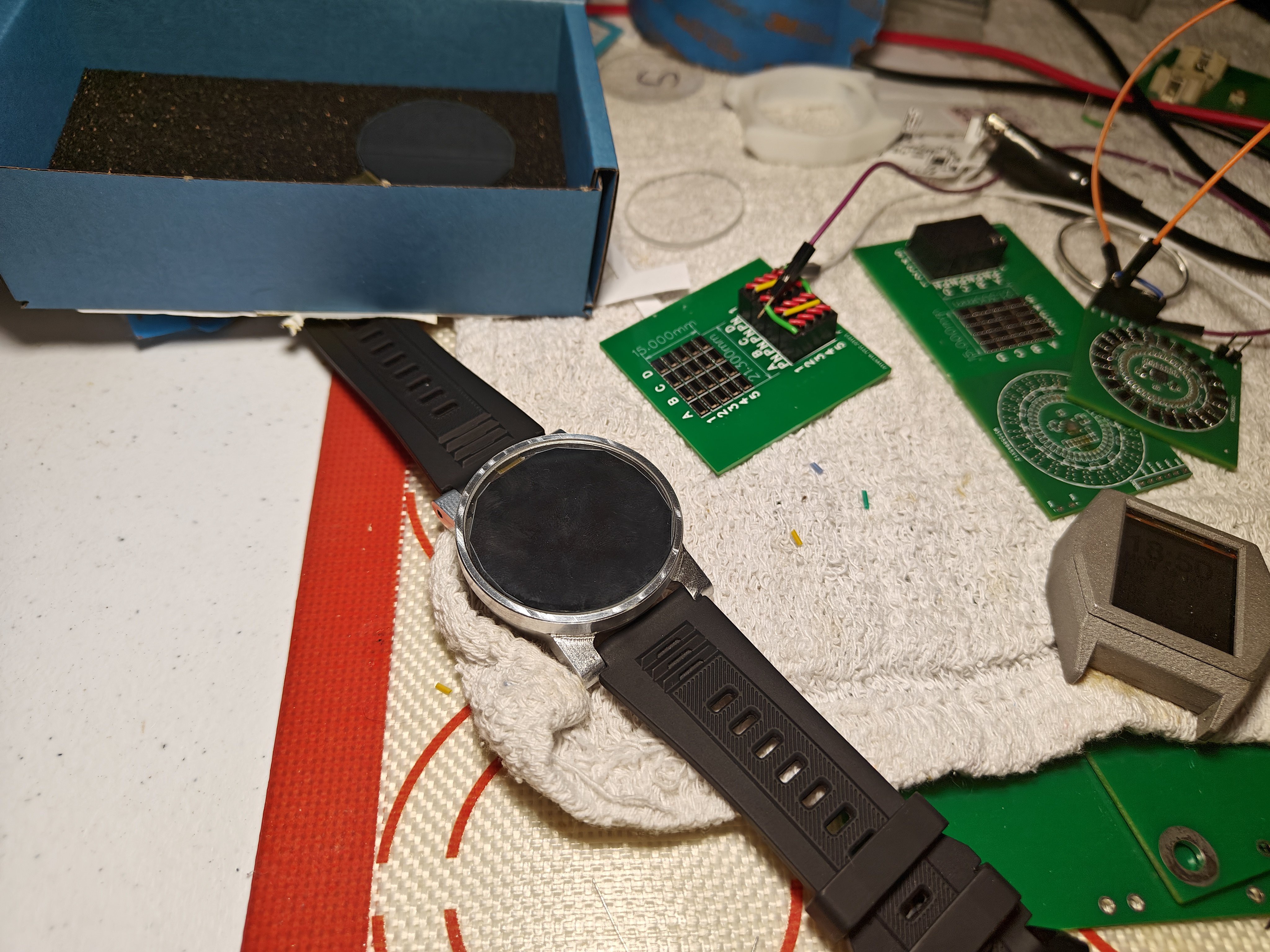
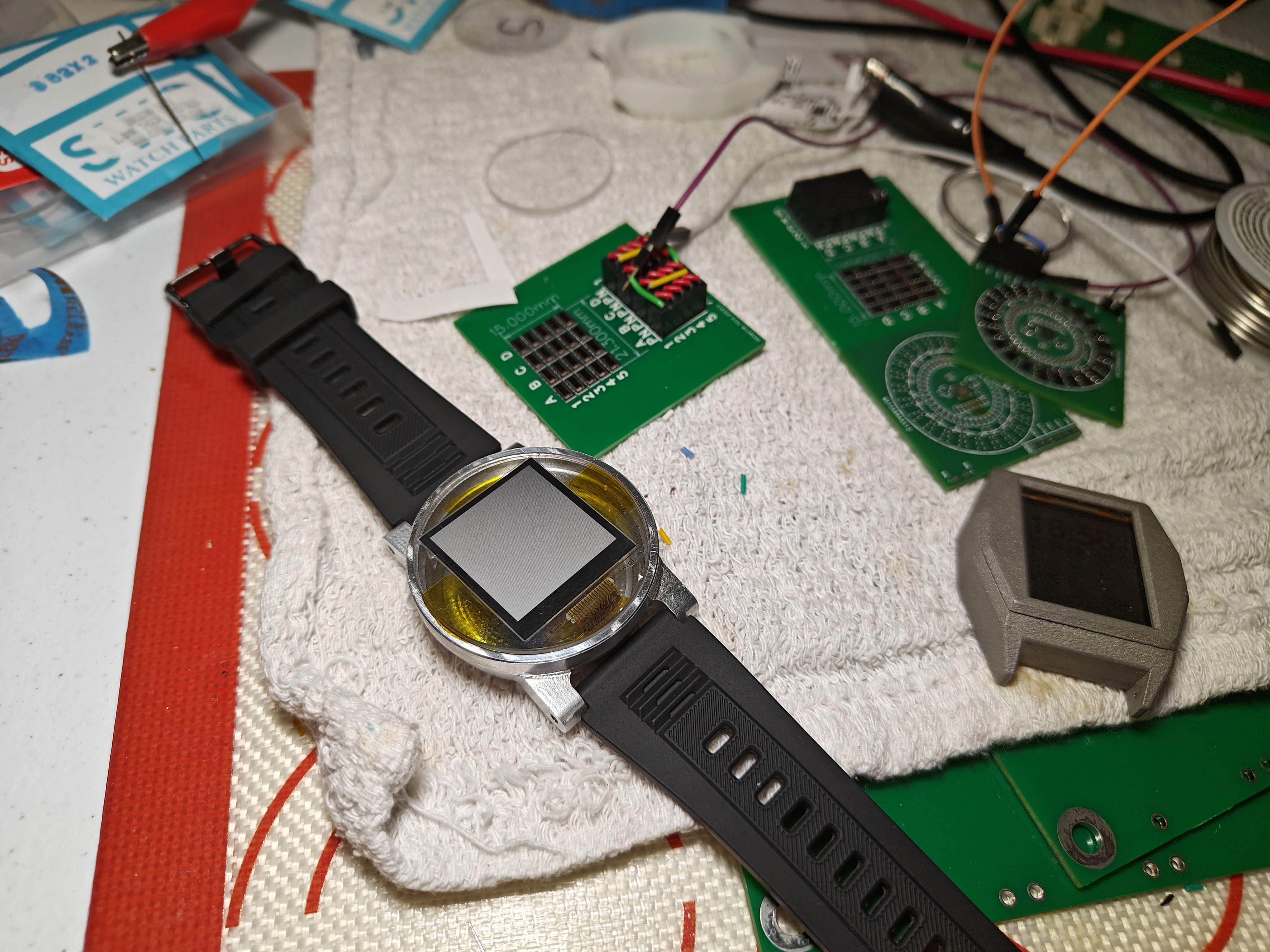
Laid my hands on really large 1.4 inch round ultra-low power transflective color Sharp LCD, will work on it in parallel, as the controls are rather complex. This is a parallel effort and might not be progressing as fast as the rest. Got two in case one breaks. These are super-hard to find, I was very lucky to procure two pieces which were miraculously in stock from a European distributor. Those are used in very high end smartwatches.
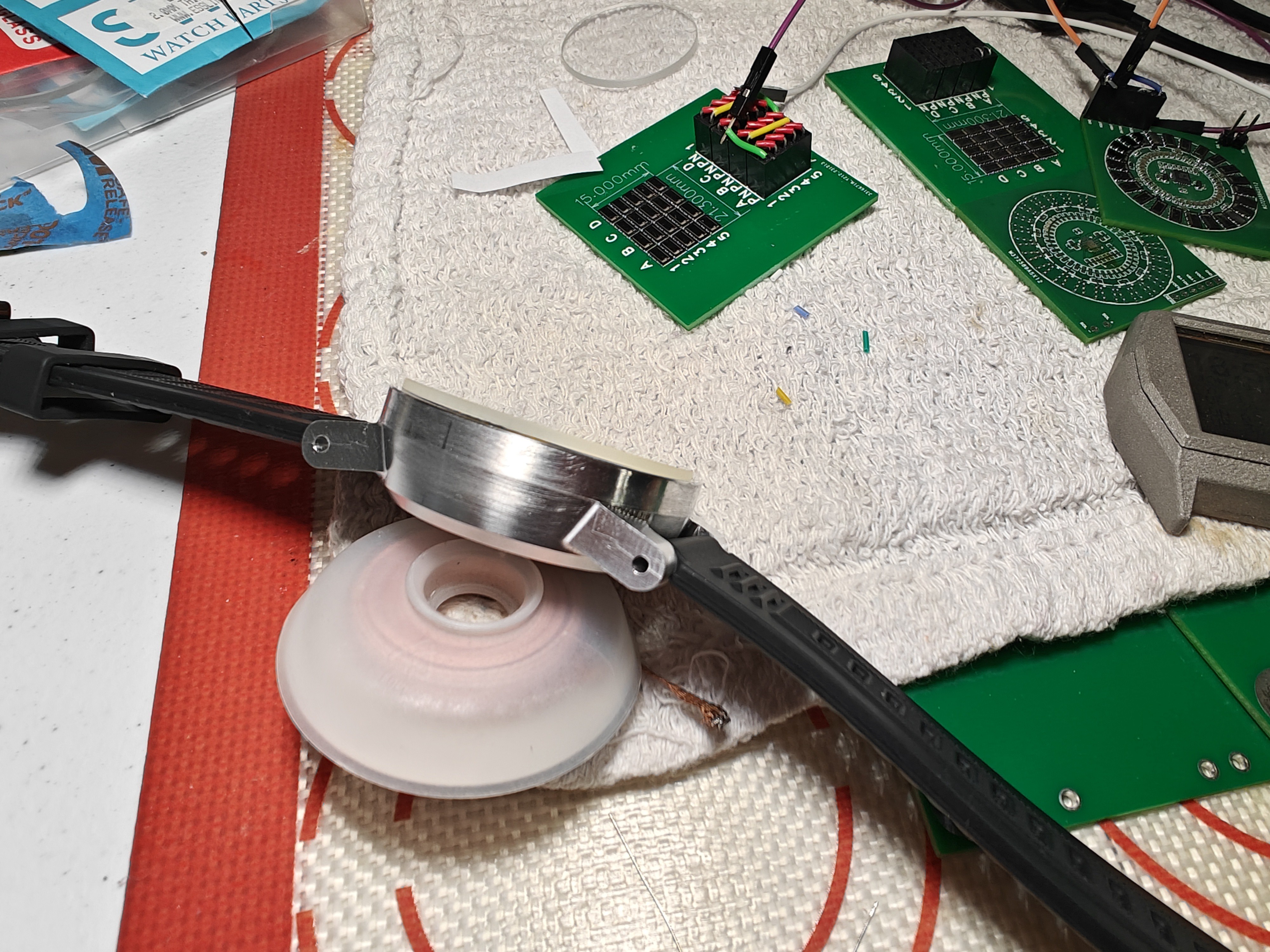
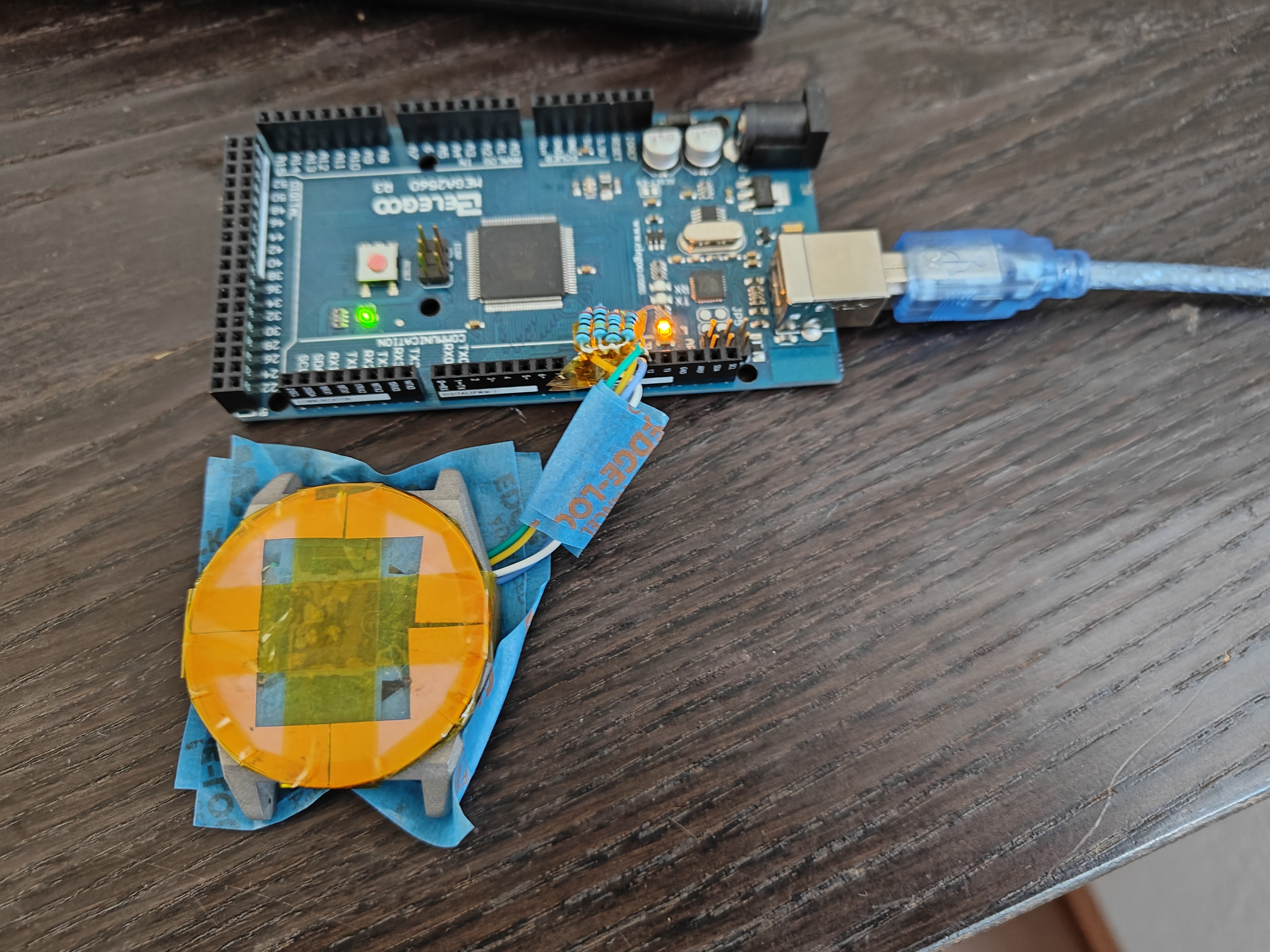
Prototyping a touch sensor screen to get the buttons working since the watch has no physical buttons. I decided to get away with the photodiodes due to complexity and added thickness.
So far so good, lots of challenges mainly with physics as the sensors are behind a thick glass face, but seems to be working, with caveats.
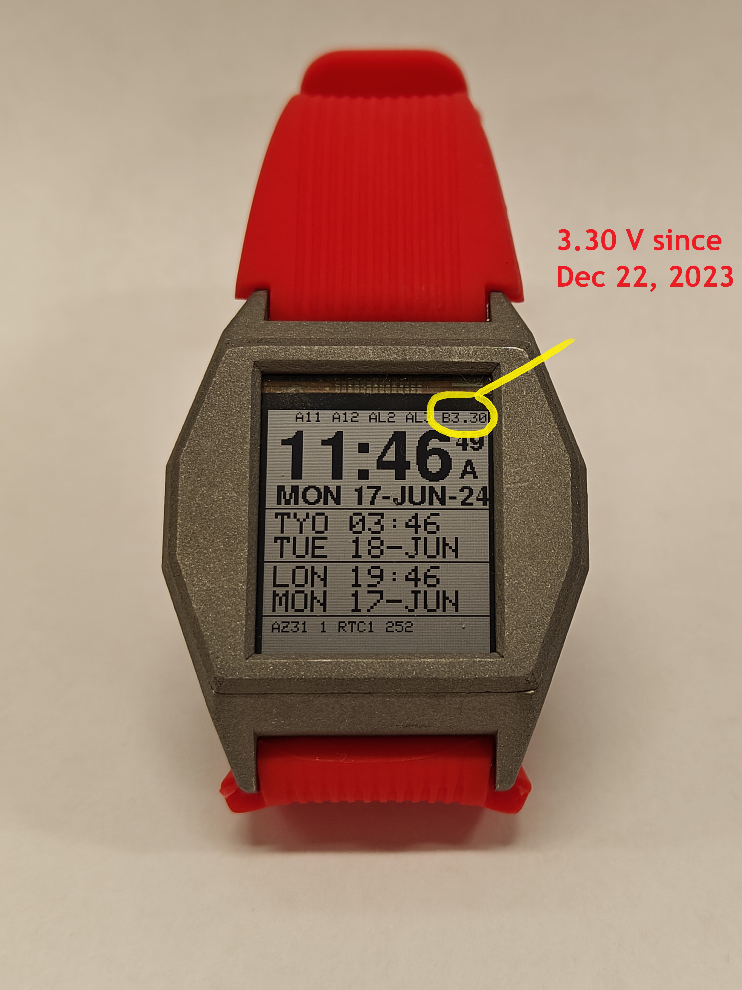
It's a long and convoluted calculation but bottom line, the design as is today will cost me 2uAh, so that would be about 50 years on a 1Ah battery drained to the bottom. I don't like that. On a 100mAh that's 5 years. Upside is of course solar charging, so make some lose some, make more than lose I guess.
The calculation was that I lost 1V in 2.45 minutes on a 400uF battery, so F*V/3600 that's about 100nAh, with 0.05 hours, that's 2uAh, give or take. Sssssss......
Haven't updated the log in a while, due to being really busy with the case and the powerplant.
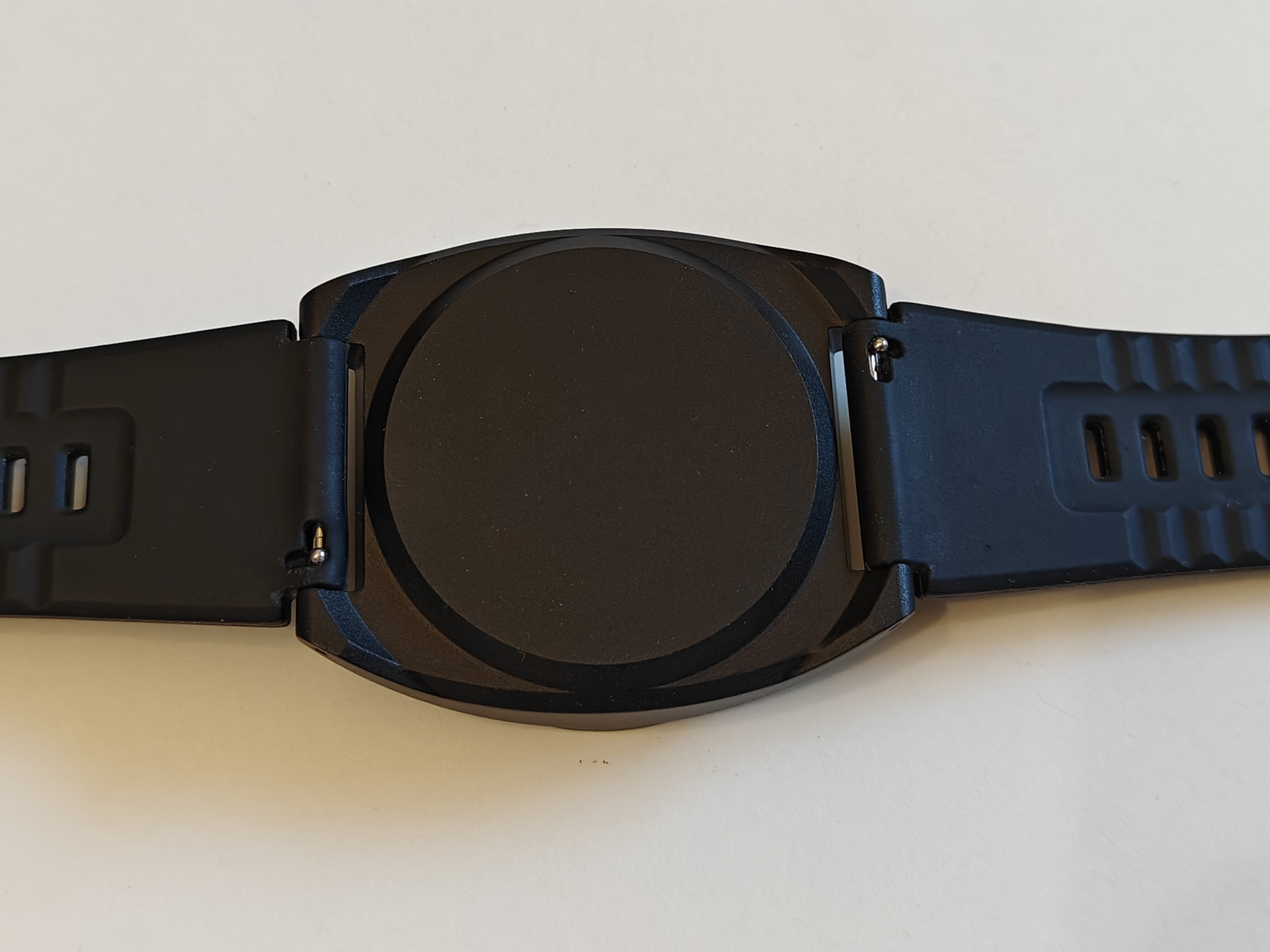
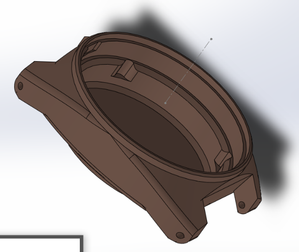
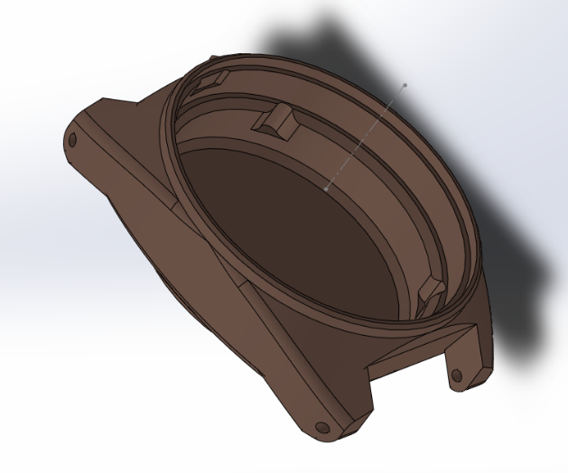
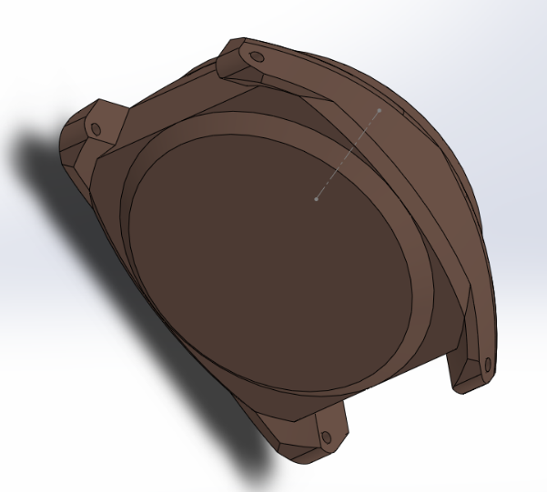
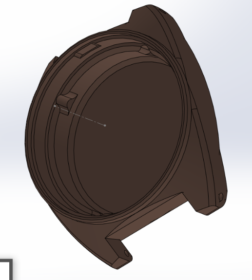
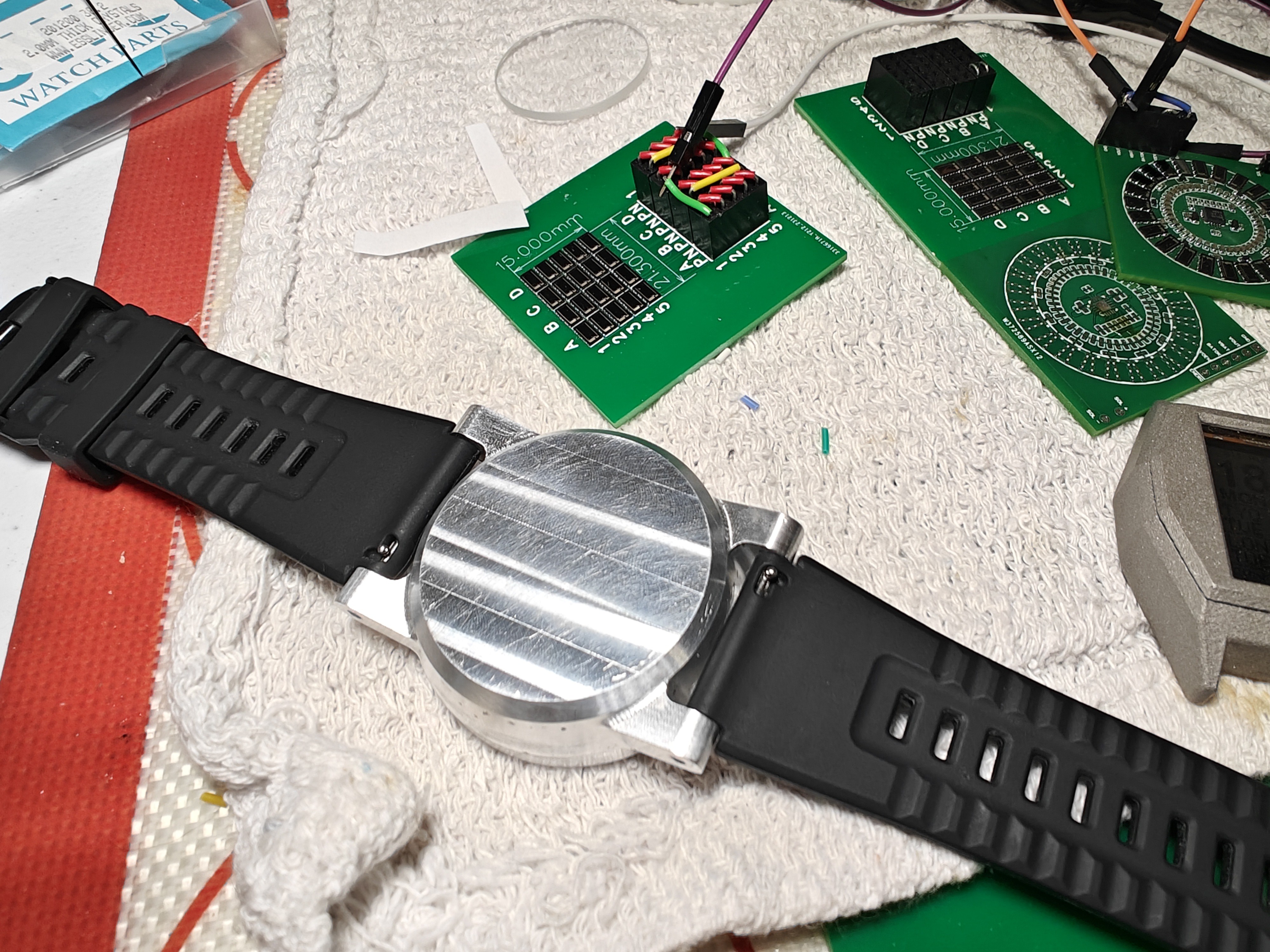
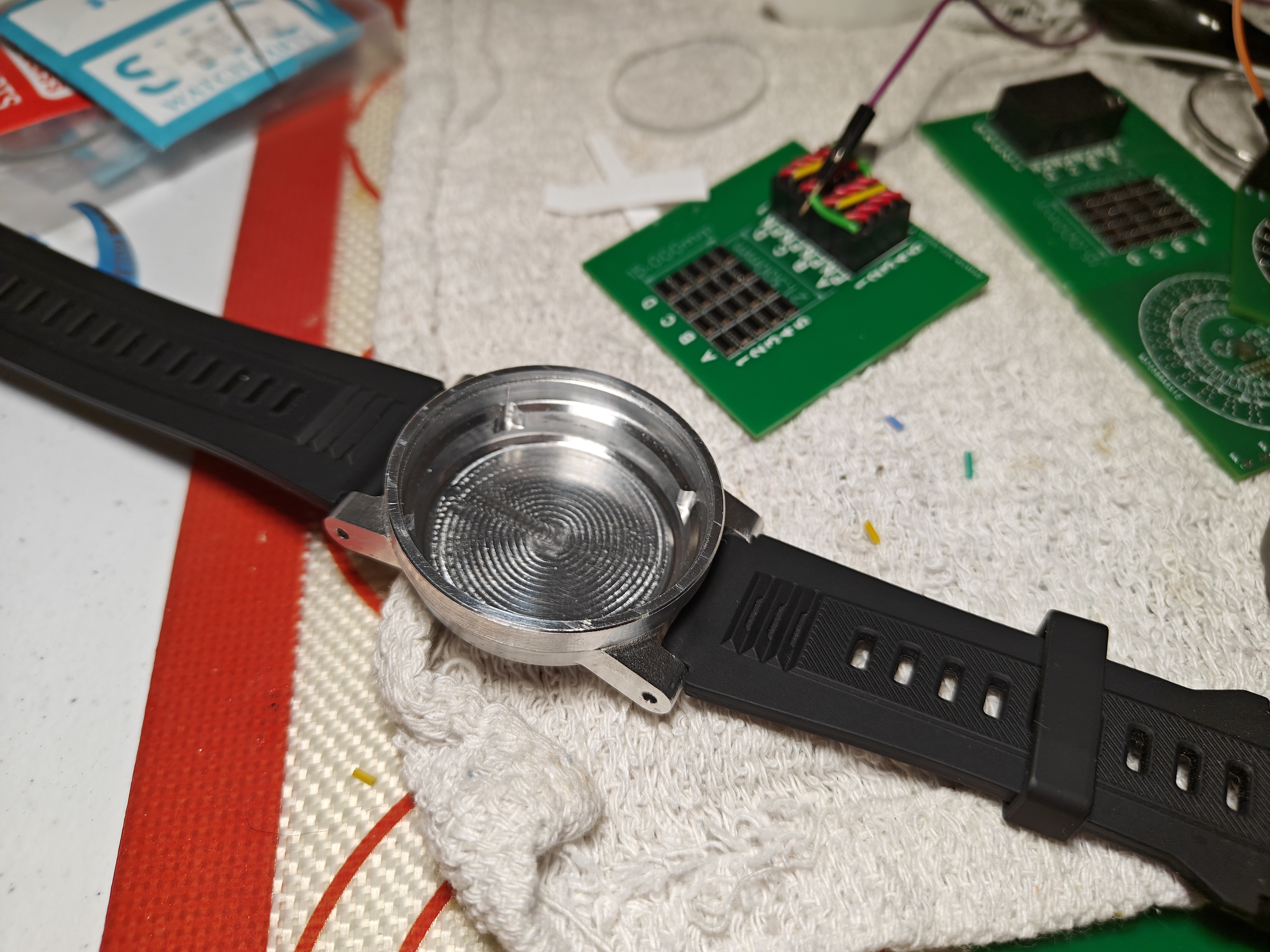
I did a full redesign of the case, will post a new log entry when I get it machined. Designing a case and manufacturing it was a major effort, hopefully this time it will work, this is revision four. The R2 and R3 were really nice but sadly they could not be manufactured. Details later.
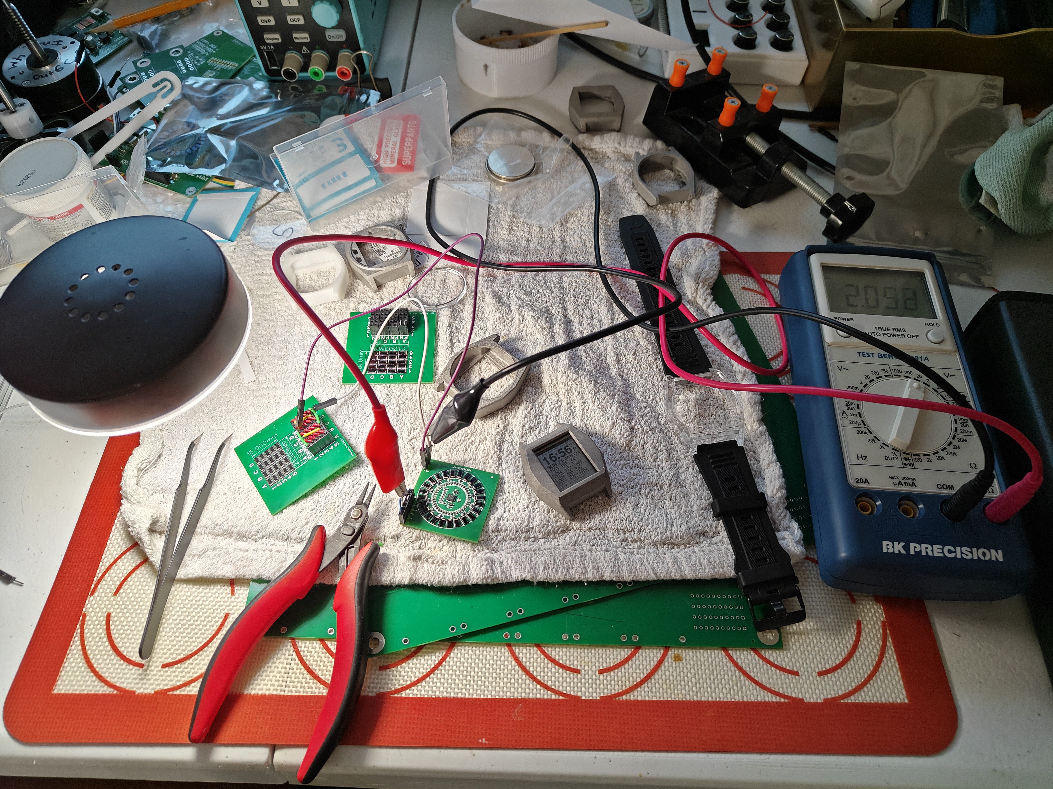
Powerplant: also some setbacks. The manufacturer could not properly SMD the design, I'm in a process of re-making it, it will take a week. Meanwhile, I was able to literally carve out (as in with a PCB mini-saw) the power portion of the design and test it.
Picture attached. I managed to read through the fifty pages of documentation for that IC and I'm getting it to the point where it's testable. There are moments I don't fully understand, but will clean up along the way.
Powerplant notes.
1. Connect EN to GND for gen mode. Connect to High for ship mode. Probably reed contact.
2. Connect vout-en to batt-ok. This will set the cold-start automatically vout-en to disable to charge the battery without powering the main circuit load, then exit cold start and enable the vout once the battery is charged to pre-set level and switch to battery + solar unless the battery drops and disable the circuit. I hope I'm doing it right.
3. For some reason the resistors I chose using the provided spreadsheet resulted in 1 volt under for both the charge and voltage out levels. This needs to be investigated, as the spreadsheet might be off or wrong or I got something incorrect during component and PCB design. It's easy to fix by experimentally tweaking the resistors however I don't feel comfortable tweaking without understanding why it works/doesn't work as designed and documented.
 VALENTINE