VALENTINE
-
PCB Breakout Test Board
11/06/2023 at 16:01 • 0 commentsBack to the proverbial mythical drawing board. My original idea of bundling the STM32 with NRF52 was a dud, even though I'm quite certain it would have worked, however, the complexity of combining all components and writing two separate firmware branches would be effort-prohibitive at that point. I have a real job, I cannot afford such a full-blown full-time effort at that point, safe for hiring a small team of SW/HW devs to finish this. Therefore, I made an executive decision to scale back a little and go native.
We go full commando! Redesigned the PCB and came up with an amazing ultra-super-nano small board.
Off to manufacturing!
Almost manufactured, SMD-ed right now. Crossing fingers. Will get it next week.
As you could see I dropped the STM32U and went nRF52 full native. Hence the massive pain in making sure the SPI worked to drive the display. Worth it!
Probably the smallest PCB I've ever designed, 8x8mm, 80 micron traces.
It's 10x10 with the antenna.
I could make it even smaller with a dual-sided design but not sure it's worth it.
Final design should be 2-layer single-side flex PCB however we cannot go that low before we confirm the correct functionality. I'm not sure my antenna calculations were correct. However, as long as I get like 10 feet / 3 meter signal propagation I'm golden.
Definitely worth exploring a chip antenna, however, at that stage it's a total overkill.
-
Display side quest
11/06/2023 at 15:52 • 0 commentsThe e-paper display seems like a bad idea, due to extremely high refresh current draw which is unsupported by the small watch battery. I could place large capacitors to buffer enough charge for a re-draw and refresh, however, the extra circuitry required to cap the charging current and space for extra capacitors seems a bad idea. SHARP Memory display has a lot better characteristics and on average the current required for both is equal. Also, it appears all modern high-end smart watches use SHARP memory displays, so I'm sure their multi-million design teams have done their due diligence and picked a winner. So, a memory display it is. I got a couple sharp memory modules from adafruit.
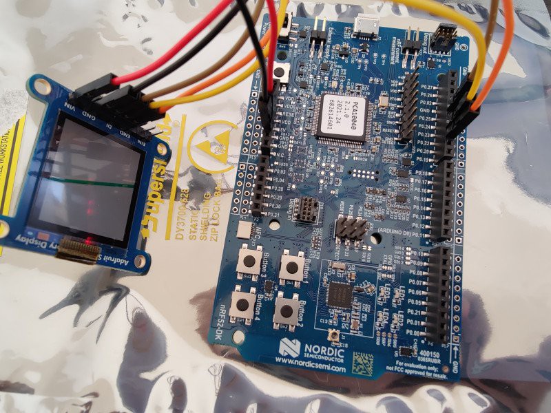
I'm using an official nRF52-DK SDK (nRF52832) from Nordic.
I'm also using Sharp Memory Display ( Adafruit SHARP Memory Display (144x168 pixels) ).
I'm trying to drive the display, but no luck. I got two displays, just in case one is faulty, but both are just showing random pattern and no communication. I'm running the built-in example from Adafruit.
The SDK otherwise is perfectly healthy, the BLE works, no problems.
Interesting...
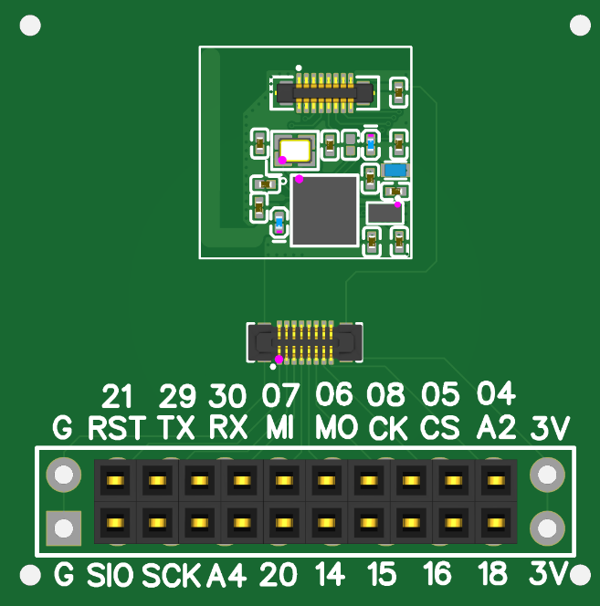
I checked if those are the actual pins by on/off -ing then and checking with an oscilloscope one by one, since the library is abysmally poor at specifying which pin maps to which integer, I had to experimentally find out the mapping, but whatever, I did it.
At that point I give up.
I'm willing to hire someone to dig into this.
Any takers?
I have low confidence this library could really work, as I see others have made it work using the Nordic basic core in PlatformIO and the same Sharp Memory display library, so I'm doing it right code-wise. Also I checked and replaced the wiring in case of a bad wire, no luck.
I would of course appreciate if anyone points me in the right direction. I might be doing something wrong. This at that point seems like a library/board definition issue.
I do have an oscilloscope but for that have something better, a logic analyzer. I ran the exact same code, except the pins, on an Arduino MEGA 2560, and it ran flawlessly out of the box, and the memory display worked as it should, no questions, there, so I captured the output, looks just like an SPI output.
The I hooked the NRF52 and the output was garbage, so it's definitely a library problem. At that point I conclude the library has an issue. Any ideas? Anything I could try to debug and narrow the issue?
The MEGA 2560 is 5V and the NRF52 is 3.3V
Yes, the nRF52-DK has 5V, that's really not the problem, it's something completely different. I wish it were that easy.
looks like the 5V is connected to Vin, have you tried using 3.3V (VDD) instead?
Nope that's really not the problem. The logic analyzer clearly shows the SPI is misconfigured.
I spent close to 20 hours but I'm on the right track. I had to re-write some of the SPI h and c, then re-point the pins to the ones away from the antenna, and now I can get correct SPI sent out to the analyzer. Before it was crapping I'm not sure why and not worth my time and effort digging.
Next is to dig into the Adafruit library to find out at what point it calls the SPI and re-write those parts too.
So, it's a messy combo of problems between the SPI for NRF in the library combined with the Adafruit's SHARP display library which relies on the underlying SPI library defaults. I would not be surprised if the adafruit bit-bangs the SPI, that would be absolutely hilarious.
I will figure it out however I'm not sure if this is directly transferrable to other's efforts. I totally suck as PRs, so could create a list of things I modified, and create an example but don't forget that would involve changing the adafruit library too, so caveat emptor.
I'm a very determined person, so I'll make it work, no problem. But definitely, the variant file and lack of documentation of which P0.xx maps to which integer on the DK is a major suck. However, I don't look a gifted horse in the mouth, so that's that.
I'll come back to report. The library is a good piece of work, it just needs some usability makeover. If I can port it to PlatformIO would be best but one step at a time.

Clearly the nRF52 hardware SPI is working fine as demonstrated here MOSI a few random bytes I'm coming back to report, the adafruit library defaults to bit-banging the SPI which creates a whole 'nather bag of problems, apparently this nrf core can't handle some of the adafruit fast pin manipulations. This is funny.
So the problem cascades leading to a comedy of errors. The adafruit library attempts to find hardware SPI, but fails, the nrf core doesn't properly advertise the availability of a hardware spi. adafruit then goes for sw spi and since it's a mosi only data it never checks if the data was properly sent and just keeps banging out while the cs, sck and mosi pins have already gone to the cuckoo clock. bang-on, baby!
I'm not really sure at that point it's worth my time digging any further. the sharp memory display library is so simple i'm going to rewrite it from scratch for nrf52 hw spi using my own changes to hardware spi headers, that's only couple hundred lines of code i need to write.
I'm putting a stop on this, if anyone wants to fix the library to properly handle spi please go ahead, i provided with enough information here.
But definitely, a proper pin mapping documentation is an absolute must.
I wrote some code to output the display clearing bytes and ran it on the hardware spi nrf board, no luck clearing the display.
Then I ran it on the hardware atmega, as it appeared the adafruit is bit-banging the spi on atmega too, this is really either sad or funny, not sure. I rewrote the code to use the hardware atmega and output the signal to the sharp memory display. Boom, the screen cleared! WTF.

AT Mega 2560 hardware SPI clearing bytes 
AT Mega software SPI clearing bytes 
nrf52 hardware spi clearing bytes So, the display clears fine with both atmega bit-bang and hardware spi, and doesn't clear with hardware nrf spi despite that the signals are identical (apart from that tiny gap between the two bytes on the nrf which is irrelevant). I even matched the css high advance of about 10uS before the clock went off, so that's that.
At that point my only conclusion is that the issue is electrical. I also bypassed as a last attempt the 5v on the display board in hopes that feeding 3v directly would make a difference. Alas, no luck. Therefore, the issue is definitely in the way the nrf works with the level shifter on the adafruit sharp board. I cannot measure the signals going into the display itself, this would require some destructive testing, and probably not worth the effort, I mean what else could it be right... but I suspect they are duds as the level shifter is crapping itself. A little known fact, the nrf being low power chip, the outputs are probably defaulting to <2.7v / 1mA low drive strength which smears the signal enough to befuddle the level shifter?
Next, bust out the soldering iron and smack that lame level shifter out of the board and shunt all the signals straight to the display. Anyways, that's how the final design will look like anyways, so if that doesn't work then we are going probably for plan D or E or whatever else next is on the alphabet.
Shunting schematics:
![]()
Let's do it!
![]()
The fix is in! With the steady hand of a neurosurgeon, the eyes of a bald eagle and the focused mind of an Olympian rifle shooter we fixed the PCB!
Victory!!!
The screen cleared! We are off to a real sprint to the end here.
Next, we try to finish editing the code to write some cool stuff. Stay tuned!
Next, after we cleared the display, it was time to ektchsually write some cool stuff. That turned to be such an adventure. Hours of logic analyzer dumps, looking into code, deep diving into documentation, crappy pin connections, mis-placed and mis-connected wires, all the beauty of hacking without any sound/solid plan and too much caffeine, enthusiasm, too short of a temper and very little patience. I'll not go into details, that's neither here nor there.
One very important oops point, Serial defaults conflicted with the SPI pins I selected, so that added another dimension of crappy confusion, was that fun or not! Oops.
Then, another issue, the problem was that GFX library required a device for the display, which was exactly what I wanted to avoid. After a load of work, I finally made it to draw a line on the display buffer, reverse-engineered all relevant logic from the adafruit library and re-wrote only the salient parts of it, then wrote a simple draw line into an array buffer and sent it to the display via my brand-new SPI routines. And there you are, a simple line on the display that took like a day of work, but we are on the right track!
Next, the real work was to be able to draw on the display buffer. That was also a rabbit hole. I looked for any library that can draw on a bitmap canvas buffer. There were a few candidates that I rejected due to a number of reasons. Then, eventually, after reverting and going over the code of the GFX library I discovered that the library supports a canvas primitive that sits under the display , where the real work is done. Reading the documentation, it appears that's exactly what I wanted.
Did some light (means read end to end a hundred pages) reading and digging and after another couple hours of coffee and coding was able to output some stuff on the display, which came out jumbled like crap. For the life of me I could not figure out what's going on. Then, I output a simple circle primitive. And then it became very clear. The Sharp display needs SPI that does LSB. The GFX canvas primitives did MSB... remember, the sharp display works bit-wise, so developing a bit-wise graphics library across unsigned bytes from scratch is not something I can lightly undertake without some extreme time/effort commitment and days/weeks of debugging, no sir, thank you. The goal here is to quick-dirty use whatever is available.
Quickly building a reverse byte lookup table (remember we have like 512k flash, that's never gonna fill up unless we want to play a kittens movie or stuff) and adding a dirty reversal loop, we got it!
![]()
That concludes the saga of the SHARP SPI memory display on nRF52. Off to building the clock, that is. Alea Iacta Est, Tempus Fugit, I and all that jazz...
-
Dev environment setup
11/06/2023 at 15:39 • 0 commentsHurray!
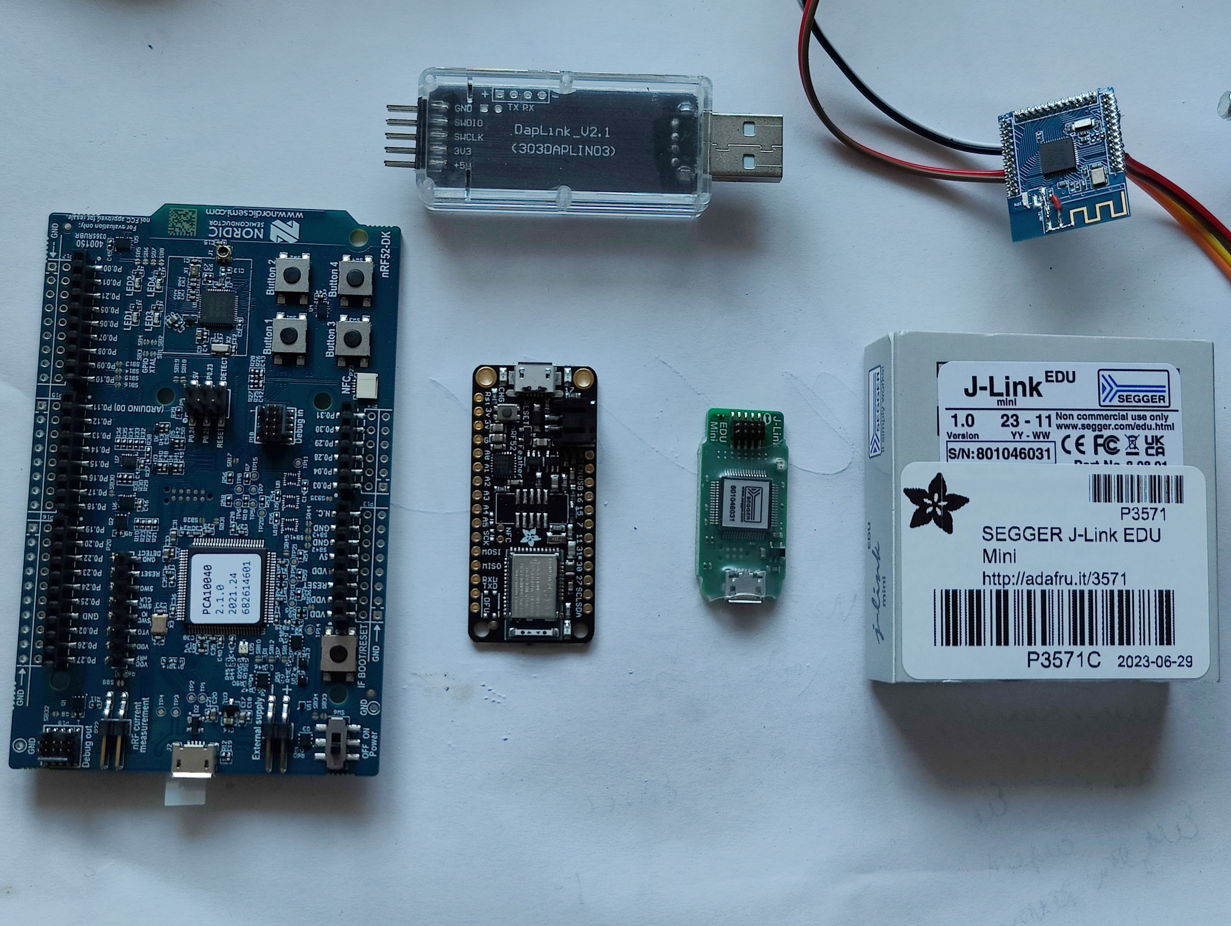
Set up my dev environment. Not very cheap but not too expensive either. Got a bunch of dev boards, cables, etc. Let's hope it's worth it! I have no idea if this is all that I need, but one way to find out! Do it!
-
Rechargeable Watch Batteries
11/06/2023 at 15:34 • 0 commentsMy quick notes on watch rechargeable batteries.
This type of watch batteries are generally split into three categories:
Manganese L
Vanadium L
Basic old-fashion Li-Ion
Manganese:1000 charge cycles at around 20% discharge depth
3V output
Large capacities up to 50mAh
Charge voltage around 2.8V to 3.2V
Vanadium:1000 charge cycles at around 20% discharge depth
3V output
Large capacities up to 100mAh
Charge voltage around 3.2V to 3.4V\
Winner here is ML2020, at 45mAh, 1000 cycles @10%, 100 cycles @50%, 20mm x 2mm, due to the small size, special overlap of charge and discharge voltage allowing for some very tricky dual-power solar charging scenarios (else needs a special harvester) and:At 45uA consumption this gives about 20 days at 50% discharge without charge, and 2000 days / 5+ years life.
At 45uA consumption this gives about 4 days at 10% without charge and 4000 days / 11+ years life.
At 4.5uA consumption this gives about 200 days at 50% discharge without charge, and 20000 days / 54 years life.
At 4.5uA consumption this gives about 40 days at 10% without charge and 40000 days / 110 years life.
Collapse
Clearly the truth is somewhere between these two numbers, and having a watch that would clearly outlive you and your children, anywhere between 5 years and 100 years, let's say we hit realistically 10uA @ 20% effective discharge, which will give us about 1000 hours/37 days at 20% discharge without re-charge, 4500 hours/187 days to full discharge, and lifespan between 500000 hours/57 years or 180000 hours/20 years definitely sounds vey attractive.We could definitely hit the 20 year life of the watch, since the STM32U575 is pulling 20uA/MHz at full throttle, 4.3 µA Stop 3 mode with full SRAM and 510 nA at standby with RTC, so assuming a once a second wake-up to perform a simple operation of updating the screen and say one an hour or even once a day wake up the BLE to pull the time, that's a winner. That would probably average around 10µAh as I'm pulling that average number out of my ass but those seem quite reasonable.
TBD check the BLE and e-paper consumption in low-power mode as that seems rather tricky.
The Nordic BLE pulls <20uA continuously while waiting for a connection and ~65uA while connected and sending/receiving data, so doing this once an hour for say a few seconds to adjust/pull the time is very reachable.
The E-Paper is a lot trickier to calculate.
Deep sleep is 2µA / no RAM retain
Sleep 35 µA / RAM retain
8 mA image update
280 ms partial update
680 ms full update
Therefore we are bound at 2uA on the low side and nearly 10mA on the high side.Assuming a full image update once a minute, and partial image update every second.
There is a display library https://github.com/ZinggJM/GxEPD which lowers the update to about 6mA.
Also there is a rather interesting discussion about power consumption on a coin battery, definitely worth the read. https://hackaday.io/project/134018-coin-cell-powered-temperaturehumidity-display
Full image update would give us 8mA * 0.68s / 60s / 60m = 1.5 uAh, say 2uAh? Not sure, that seems too low.
Partial image update would be a lot trickier, I cannot do it now. TBD.
The e-paper is definitely the power hog here. May have to change it perhaps to something else?
More discussions here: https://www.pervasivedisplays.com/why-e-paper-displays-will-run-for-22-years-in-coin-cell-powered-iot-applications/
More to come. Best would be make the setup and measure. I might be just full of hot air and all this is not attainable or has some basic errors.
-
Ad-libbing a circuit
11/06/2023 at 15:30 • 0 commentsTook me a weekend to design the alpha-version of the PCB. Lot's of documentation to read, component selection, placement, wiring, routing, design decisions, DRS, manufacturability, machinability, and way too much EM/RF physics to take into account. The design won't win any awards but it's a starting point.
![PCB Alpha Dev 001]()
-
Basic design points
11/06/2023 at 15:28 • 0 commentsStarted ad-libbing a circuitry. Solar powered, with a battery.
Ultra-low power. So many choices. Components galore.
My vague idea is to create a circuit based on a massive dragnet of ideas from other circuits, features, and available online. End goal is to be manufacturable end to end with no in-house work but out of box, all components in stock. Cost is irrelevant.
After a massive search I stopped at
MCU: STM32U575 — ultra-low power
BLE: Nordic
E-Paper: Waveshare
Battery: SEIKO Manganese Lithium
Antenna: Self-made built-in
TIMER: Go with the internal.
Took me a week to search for the components.
Must eventually go with external timer. Currently found a seiko/epson crystal 20ppm accuracy, way too low but fine for development.
Need something better than 5ppm, or even better 1ppm at 32k, which is like what, 5 sec/month error? Now it's a second per day error depending on temperature. There are temperature controlled/corrected oscillators or external timers. Seiko / epson seem the way to go but later for a future iteration.
Smartwatch 10 Years Ultra-Long Battery Life
Smartwatch wearable, ultra-long life measured in years, no need to recharge.