Tamas Feher
-
BJR_LOG_04 Dynamics analysis
11/15/2023 at 13:55 • 0 comments
In the next log, I will choose the motor for the actuator. To be able to do so, I will need to set some requirements. Mostly:- Maximum stroke length
- Maximum output force
- Maximum velocity
My way of figuring this out spawns from quadcopters (Bear with me on this).
A general (often wrong) rule of thumb when sizing the motors for a quad is to have twice the amount of thrust that's needed to hover. Why is that?
It boils down to control authority. Which means how much can you influence your controlled variable.
For your system to be effective, there needs to be enough control authority to perform the intended action, and some more to be able to compensate for disturbances. Going back to the quadcopter example: If the motors are producing a 100% thrust just to hover, they don't have enough headroom to control the tilt of the craft. Any small breeze would send it spinning, making it unstable.
That's why the output thrust is chosen to be what's needed, and some more on top of that.
Doubling the value is an easy guesstimate that can be tuned further once the prototype is ready.
In this case, we can start the analysis by looking at the most demanding use case, which is the fast circling of the ball.
The speed of circling is 200 Deg/s, and the diameter of the scribed circle is 130mm.
![]()
The linear velocity (blue arrow) of the ball can be seen changing direction, but not magnitude.
The change in velocity direction is due to centripetal acceleration (red arrow). To calculate the magnitude of this acceleration we can use this formula:
where:
- a is the centripetal acceleration
- omega is the angular velocity
- r is the radius of rotation.
Plugging the values into the equation we get a = 0.792 [m/s^2]
The ability to exert acceleration on the ball is our control authority. So this is the value we will double to give enough headroom. Giving us a = 1.584 [m/s^2]
The next topic is about how can we influence the acceleration of the ball through tilting of the plate. I will not go into the breakdown of the dynamics of a sphere rolling on a slope, but here is the formula:
Where:
- g is the gravitational acceleration g = 9.8067 m/s^2
- phi is the tilt angle of the plate
Rearranging the formula we can get the maximum plate angle needed, which is 13.069 degrees.
So now we've got a requirement: The plate needs to be able to tilt +- 13.069 degrees.
Next we can analyse how fast we need to be able to tilt the plate. The plate can tilt in pitch and roll directions.
If we look at the plate from the side, we can see that during motion it tilts in a sinusoidal wave.
![]()
We can express the plate motion through this formula:
Through derivation, we can express the plate tilt angular velocity:
The upper limit of this function is where cos equals 1, meaning our maximum plate speed is the maximum plate tilt times ball angular velocity, which is 0.796 rad/s
To get the maximum plate angular acceleration, we can derivate once again:
Once again expressing the maximum value of this function by replacing sin with 1:
Plugging in the values for the equation above, we get the maximum plate angular acceleration: 2.779 rad/s^2
Now we are finished with analyzing the plate, and we can move on to analyzing the linear actuator capabilities.
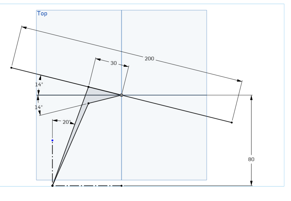
Now moving on to evaluating the needed stroke length for the linear motor. for this, we need to do geometric evaluation.
We can consider the center of the plate being pinned in space, and tilting around it.
The first variable we need to figure out is where the piston attaches to the plate. you can imagine a lever here
If it attaches close to the center, the stroke length will be shorter, but larger forces need to be applied and if it's closer to the edge, the stroke length is higher, with lower forces involved.For visual appeal, I chose a radius of 30 mm, but that can be tuned for the motor selected.
Another important factor is the minimum internal tilt for the actuator is set to be around 20 degrees.
I didn't have the energy to break it down into equations, so I used a neat trick to obtain the values: Using CAD sketches in onshape I can easily get the necessary lenghts for my actuator:
With this I got the minimum actuator length: 79.37mm and the maximum is: 92.85mm. Giving me a stroke length of 13.5 mm
Okay, we are almost there. now we just need to consider the maximum linear velocity, and the maximum force needed.
I'll simplify the following calculations by not considering the internal tilt of the actuator, but rather considering it directly under the 30 mm joining point, making it perpendicular to the plate.
From the maximum plate angular velocity, we can calculate the maximum velocity of the actuator:
The actuator velocity comes out to be 23.8 mm/s
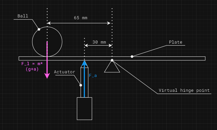
To finish up the calculations, we only need to get the worst-case force exerted by the piston. To set up the worst-case scenario, imagine the is plate accelerating the ball upwards with the maximum plate acceleration. The ball is positioned at the far end of the piston assembly.
The mass of a 20 mm diameter stainless steel ball is 33g. I'll consider the mass of the plate together with the mass of the ball for simplification.
In the earlier log we've established the technology for ball detection will be contained within a pcb, so we can estimate the weight of the plate by the weight of a 200mm x 200mm pcb, which is approximately 148g.
All together the mass that needs to be considered is 181g
The upwards acceleration of the ball can be calculated through the maximum angular acceleration of the plate
The upward acceleration of the ball comes out to be 0.18m/s^2. It's negligible next to the effects of gravitational acceleration, but I will still consider it, as I put so much effort into calculating it.
From this point we can calculate the force exerted by the ball and plate on the actuator. Taking the lever forces into account:
Expressed from this equation we get the necessary actuator force to be: 3.91N
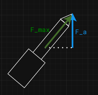
At this point we can start reintroducing the internal tilt of the actuator, as coming form the onshape analysis, the worst case actuator tilt compared to the plate is around. 37 degrees.
Where Beta is the worst-case relative tilt of the actuator compared to the plate
All together the maximum actuator force comes out to be 4.9N
Through a long and treacherous journey, we managed to obtain all the requirements needed to select an actuator
- Minimum stroke length: 13.5 mm
- Maximum output force: 4.9N
- Maximum velocity: 23.8 mm/s
Is it over-engineering the problem? Certainly. The reason why I went into such depth about the requirements is that I was interested mostly in direct drive applications, where there are no reduction gears. This usually means lower forces. So I wanted to make sure I know what kind of forces I need to deal with before selecting the actuator.
-
BJR_LOG_03 Plate subsystem breakdown
11/12/2023 at 18:09 • 0 commentsIn the earlier log, I broke down the project into smaller subsystems. This time let's analyze the first subsystem, the "Plate"
Let's narrow our options by specifying some requirements:- The whole assembly needs to fit in a 20cm diameter cylinder, so this is true for the plate as well.
- The sensing of the ball needs to have a high enough resolution that it can sense at least 100 marks in each direction. This is a control system good practice. With too low resolution the ball would jitter instead of holding the target. The earlier requirement set up a 20 cm diameter, so we can say that it needs to be able to detect within the accuracy of around +- 2 mm
- The sensing method should have a high enough refresh rate that it would achieve smooth operation. My usual rule of thumb is to use at least a 100 Hz refresh rate for mechanical control systems. This means anything that involves F=m*a.
Given the requirements, I started researching touch-based sensing technologies. I selected 3 touch-based technologies that I would like to run up against each other:
- Resistive touch sensing:
In a resistive touch screen, there are 2 conductive films separated by a thin layer of air gap. Once something applies pressure to the top film, the contact is made by the 2 conductive surfaces. opposing edges of the films are connected to electrodes, so if a voltage is applied across them, with the contact point it forms a voltage divider. The voltage can be measured and from there the touch location can be interpreted.
![How Does A Touch Screen Respond To Touch? » Science ABC]()
The benefit of this technology is that it is very simple to control and widely available. However the downside so far I've only seen rectangular units being produced, and the ball needs to be heavy enough to overcome the stiffness of the top surface.
- Capacitive touch sensing:
In this case, we are interested in a capacitive touch array instead of individual touch buttons.
Capacitive touch arrays operate on the principle that a finger (or a conductive material) would disrupt the electrostatic field around the electrode, and change the capacitance between the TX and RX electrodes. This change in capacitance is recorded as a touch input.
![Projected Capacitive Touch Screen | Capacitive Touch Sensor]() This is the technology used in smartphones to detect user input.
This is the technology used in smartphones to detect user input.The benefit of this technology is that it can be all self-contained on a PCB, allowing any form factor. However, the downsides are that the ball needs to be conductive, and it requires more advanced PCB design.
- Infrared touch sensing:
On the edge of the touch surface, rows of infrared emitters and receivers are populated at the position of the touch, the beams are blocked by the object, registering a touch point.
![Infrared touch screen technology | Reju Technology]() The benefit of this technology is that it does not impose any major restrictions neither on the surface, nor on the ball. The downside is that it requires a border around the perimeter of the plate, which would be visually unappealing.
The benefit of this technology is that it does not impose any major restrictions neither on the surface, nor on the ball. The downside is that it requires a border around the perimeter of the plate, which would be visually unappealing.- Optical tracking.
As a last technology, I chose to evaluate machine vision, as it's a common technique in ball-balancing projects.
Unfortunately, it means a camera needs to be mounted high above the plate. this would impose aesthetic issues, also restricting the material selection for both the plane and the ball.I won't go into other touch-sensing technologies such as Surface acoustic waves, or projected capacitance methods, as they go over my head way too far for me to understand them.
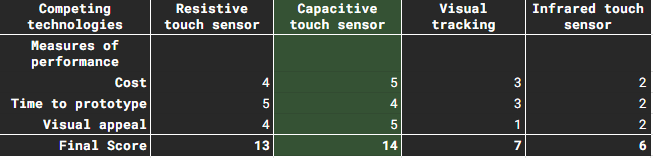
Now that we've set up the contesting technologies, a decision needs to be made on which one to pursue further. My usual method for this is using the decision-matrix method.
In this method, measures of performance (MoP for short) are assigned to the technologies. In this case, I chose a scale from 1 to 5, where 1 is the worst performance and 5 is the best.
Once the ratings are established for all technologies and all MoPs, the scores can be summed together. The highest-scoring technology wins.
The choice of MoPs is individual to the project and the environment, so choose your own MoPs if you would like to try this method.
I chose:- Cost
- Time to Prototype (how long it takes to finish a prototype)
- Visual appeal (how much of an eyesore it is)
Given these MoPs, here is the decision matrix:
You can see in the table that even if the resistive touch sensor is the easier to implement, The capacitive touch sensor wins as it's more cost-effective, and enables a thinner plate to be used.
Note from the future: As I'm moving deeper into the design, cost-effectiveness becomes less of an advantage over resistive touch screens, but let's see how it turns out.
-
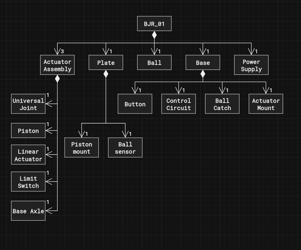
BJR_LOG_02 Subsystem breakdown
11/09/2023 at 19:09 • 0 commentsOnce a set of high-level requirements was allocated, the next step is to start breaking down the project into subsystems. The next diagram shows the high level block definition diagram of the system.
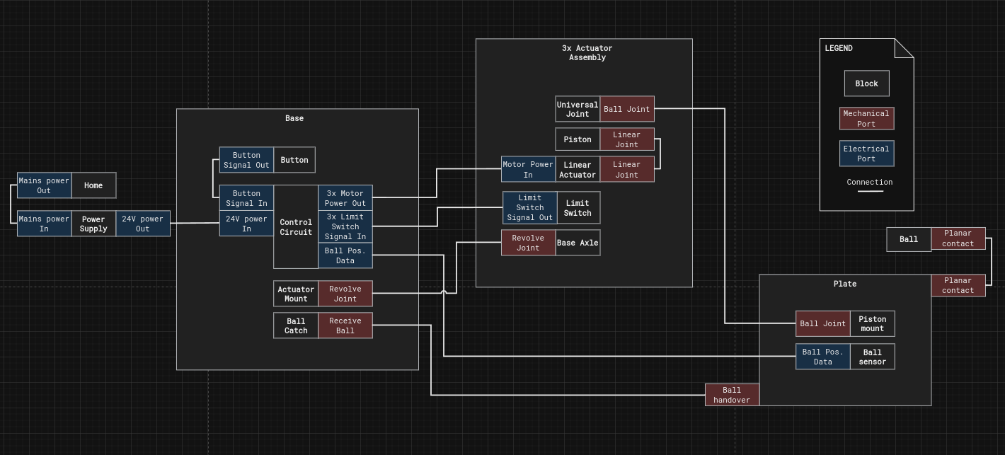
Once we have the high level Items declared, the next step is to define how they interact with each other. This is usually done through the introduction of ports and connections.
I will not represent fastened connections on this diagram as it just makes the view cluttered.
The ports are represented as coloured flags attached to the blocks.
Red color means mechanincal connecitons, and blue color means electrical connections.
This view will help us when we narrow our focus to each of these elements.
The kinematic arrangement I'm using is called the 3-RPS parallel manipulatorShout out to Aaed Musa for the great video he published on a ball balancing robot using the same arrangement. The video can be found here.
-
BJR_LOG_01 Requirements gathering
11/08/2023 at 23:17 • 0 commentsEvery good project I had started with taking a moment to consider the requirements.
I know it's not the most riveting content, but it will help to set the stage for later decisionsMy usual approach is to identify the stakeholders and think about how they would interact with the device.
The main stakeholder is the person who would own this device, so let's start with that one.
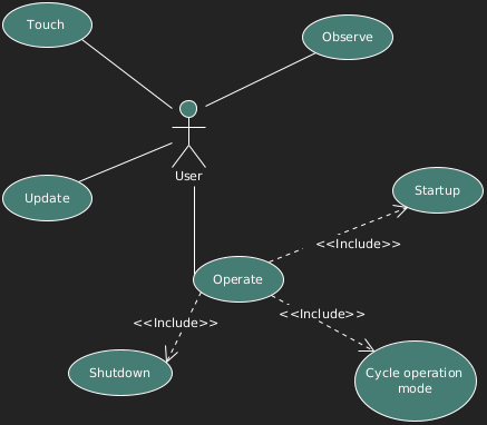
The user would operate, observe, update, and touch the device.
![]()
The operation can be broken down into 3 other use cases:
- Starting up
- Shutting down
- Cycling operation mode
Next, we can assign requirements to the use cases.
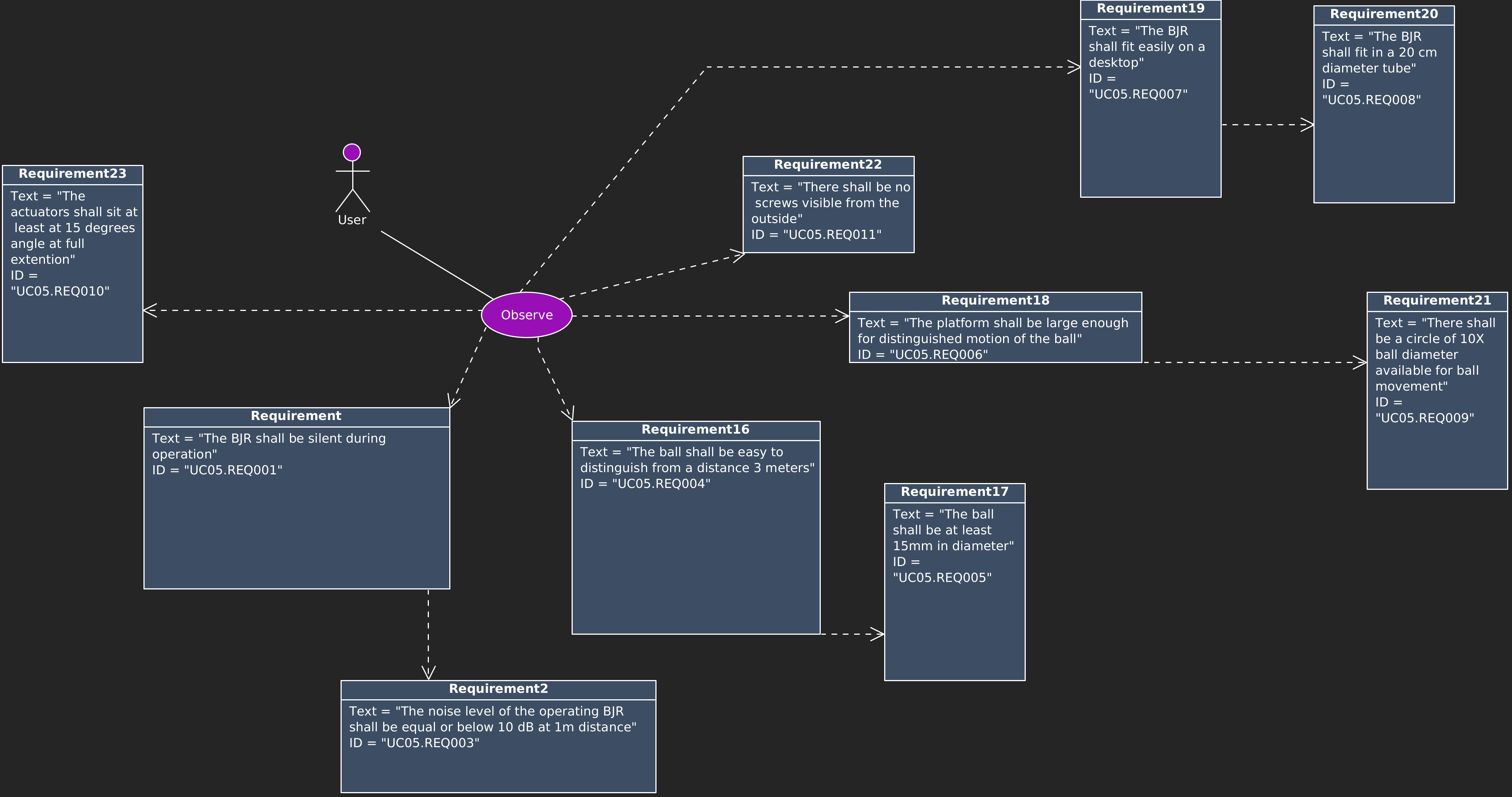
Starting with the Observe use case, the high-level requirements are:
![]()
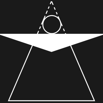
The visual intent of this project is to have a silhouette similar to this shape:
![]()
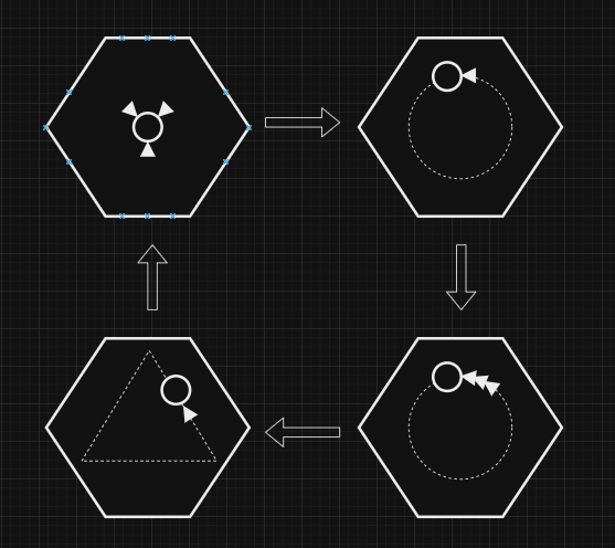
There are 4 Main operating modes:
- Keep at center
- Circle slowly (20 deg/sec)
- Circle rapidly (200 deg/sec)
- Trace a triangle
![]()
The user can cycle these operating modes by pressing the button on the device.
To start/shut it down, the user must long press the button.
When the device finishes the start-up procedure it shall visually signal it to the user.
When the device receives a shutdown command it shall safely discard the ball from the plate if it's present. Otherwise, it would just roll off from the plate.Let me know if you prefer more architecture building logs or want me to jump into the hardware build.


 This is the technology used in smartphones to detect user input.
 The benefit of this technology is that it does not impose any major restrictions neither on the surface, nor on the ball. The downside is that it requires a border around the perimeter of the plate, which would be visually unappealing.