 Michael Gardi
Compared to the dead bug wiring of the previous version, putting together this new MacroPad couldn't be easier.
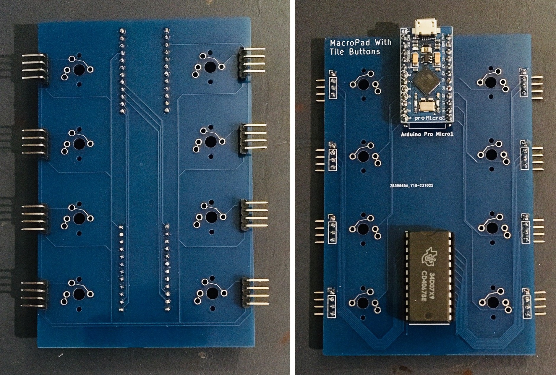
- First soldered in a 24 pin socket and install the CD4067BE 16-Channel Analog Multiplexer.
- Insert the pro Micro so that the legs of the header protrude from the bottom of the PCB about 1 mm. Solder the pro Micro in place.
- Solder in the 4 pin 90 degree male headers as depicted below. (Note: my original plan was to have the 90 degree headers mounted the other way so they would be on the inside of the base. I changed my mind because I thought it would be too hard to plug in the wire plugs from the tile holders. Also I think there needed to be more "slack" between the tile holder an the PCB to allow the buttons to move freely. As a consequence the header now extends a few mm below the bottom of the base. For this version I will simply add some rubber feet to the base. I have increased the depth of the base on the 3D model so this will not be a problem for subsequent builds.)
With the eight Fubata MD-4PCS switches inserted, carefully slide the PCB over the switch pins. Be patient and careful as it's a little tricky getting all of the pins to line up.
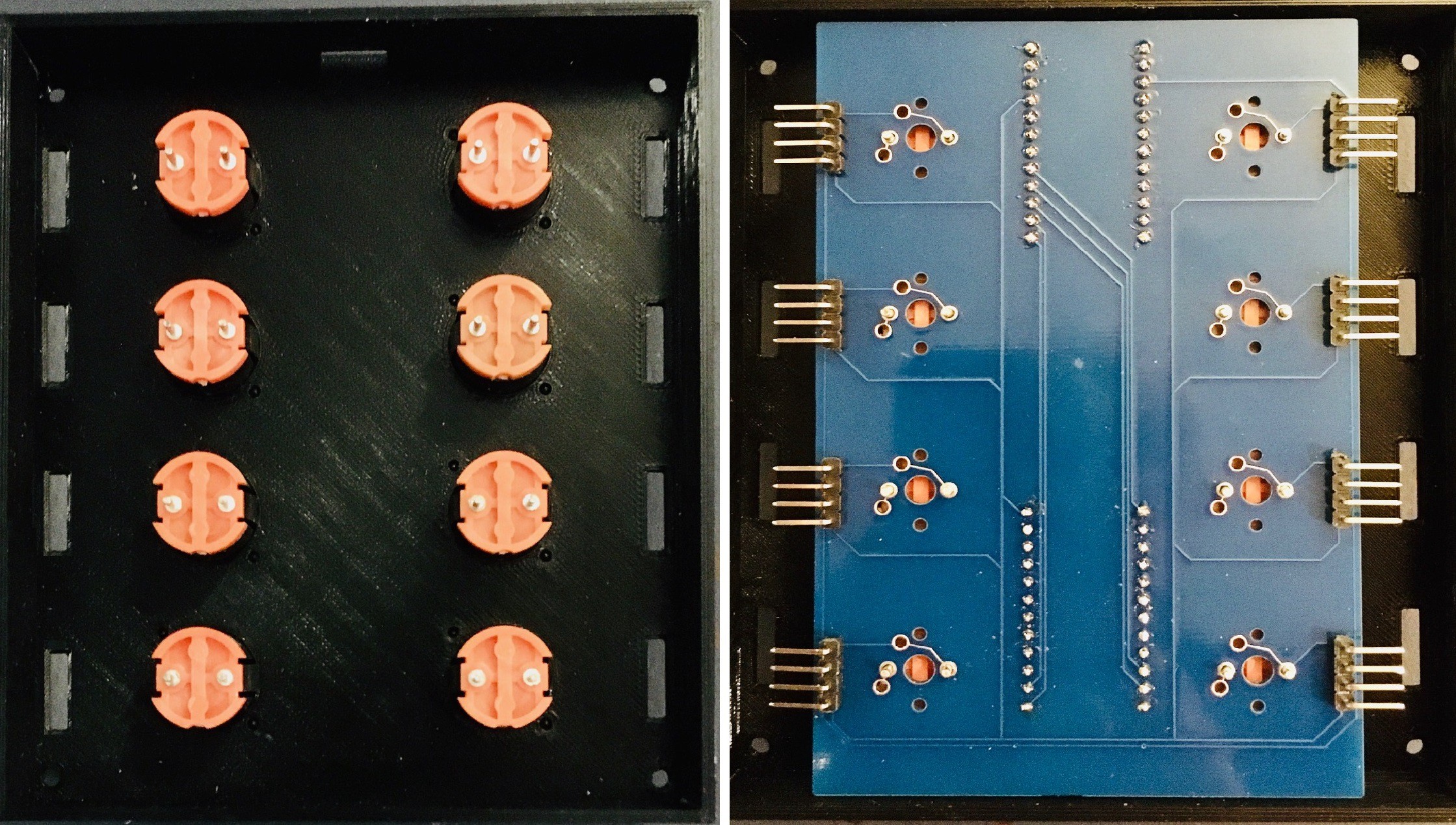
At this point I did not solder the switch pins in place because I was not sure how hard it will be to plug in the wire harnesses from the tile holders later on.
NOTE: When you do solder the buttons to the PCB, make sure that the buttons are inserted flush with the base or else the switch could end up tilting a bit which causes them to scrape against the slots in the top of the base and possibly stick. Don't ask me how I know.
Preparing the tile holders and adding the wire plugs is my next task.
Discussions
Become a Hackaday.io Member
Create an account to leave a comment. Already have an account? Log In.