I have started section #3, levels 120 through 180. The structure is printing up well, no need for modifications so far. As it turns out the levels 140, 160 and 180 all have the same floor beams and legs. I didn't plan it that way, its just the way it turned out. I have also designed Swing Arm #3 (easy) and I'm working on Swing Arm #4 (difficult).

A word of caution regarding the lights. I started out using as it turns out a very non-transparent gray filament. Everything was good until I needed more filament and the filament was no longer available. Without thinking I selected a new filament that was close to the same color and used that for the lights on Swing Arm #1. Only when the arm was completely constructed and attached did I realized the new filament was too transparent. This new filament has been OK for the various boxes and cabinets that sit on the floors, but not for the light shades. I eventually was able to get a new spool of the original filament and immediately printed up all the light shades I expect to need. So check the transparency of the grey filament before installing too many lights.
The structure and inner parts of level 120-140 is complete. This is the first floor of the next removable section #3.
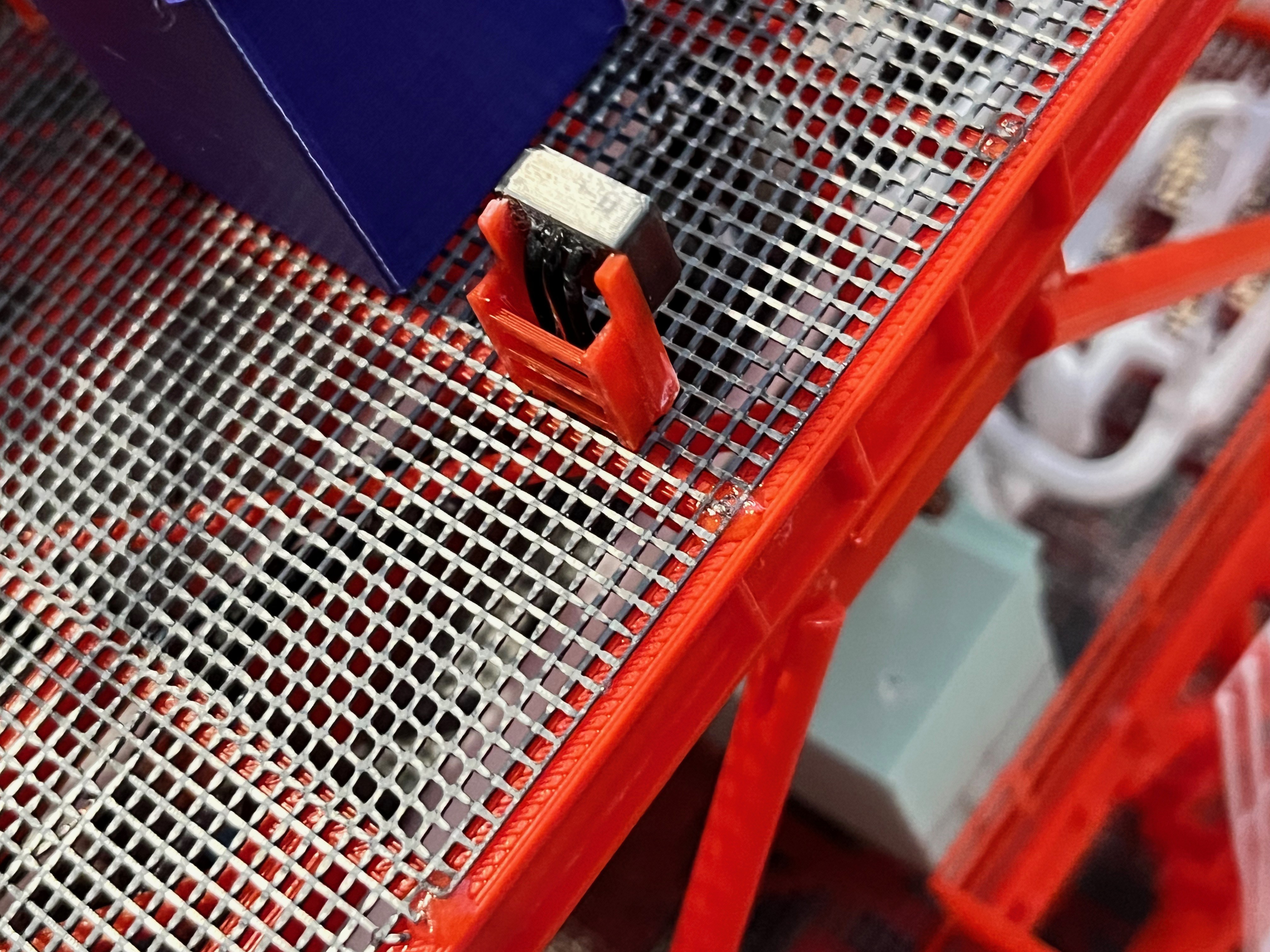
Thoughts on the Aviator67 parts. The part names align with the naming of parts in the MicroArtwork pdf files. Some of the names, usually storage boxes, for some reason do not have the same "Equ" number as in the MicroArtwork. I have not attempted to rename these. I have noticed that not all the parts have been modeled. There appears to be a size cut-off, too small and its not there. At the scale of this model, there are a few parts that I believe should be modeled. Many of these are small boxes that hang off the outside railing and are therefore fairly visible. Some of these boxes are about the same size so I created one box and will use that for many purposes. Specifically this part is named "L140 Crane Control Station". I first decided to model these at the next level. I may go back and add some of them to lower levels since the outside rails are easily accessible.
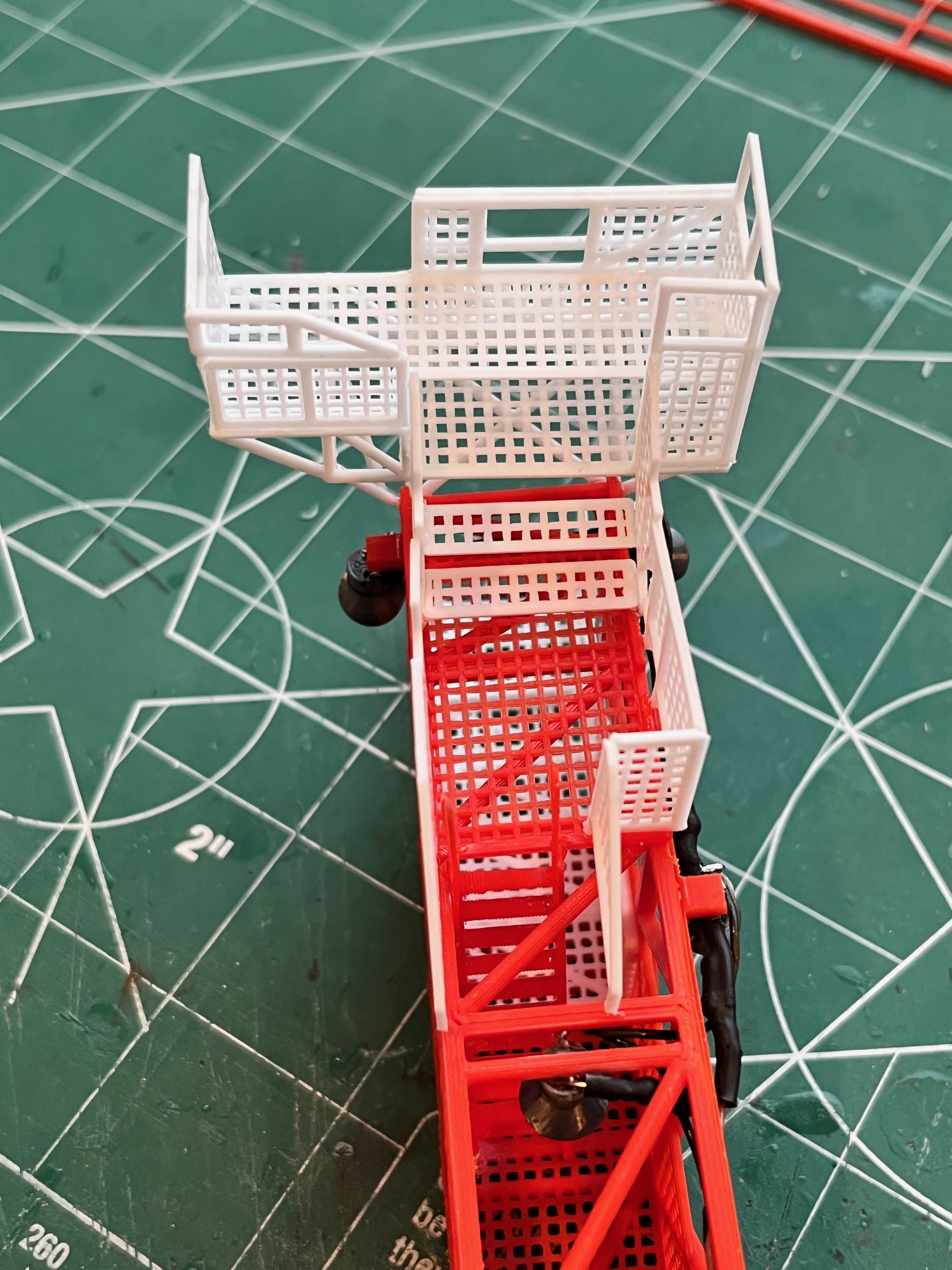
Level 120-140 camera platforms: There are two side ones and the standard corner one. They all have ladders to access.

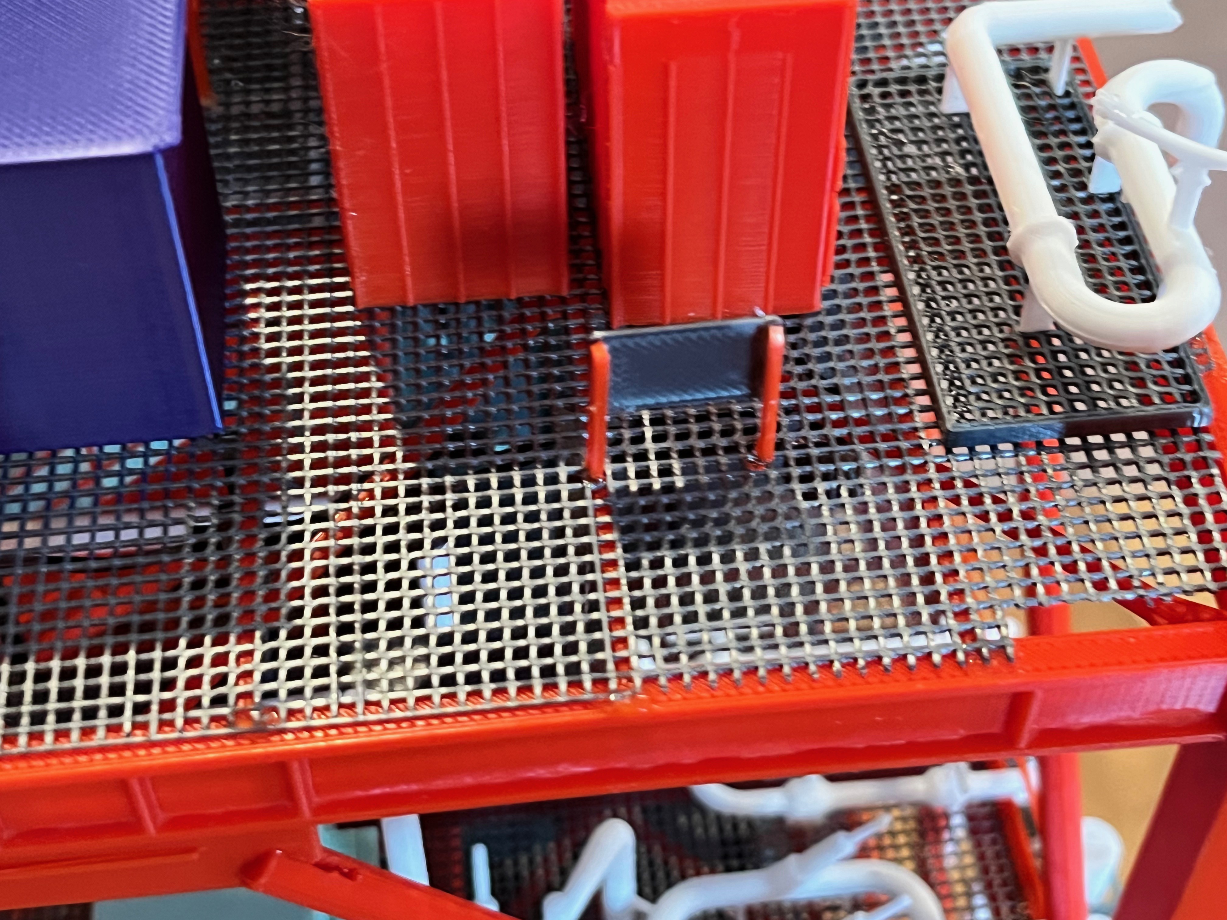
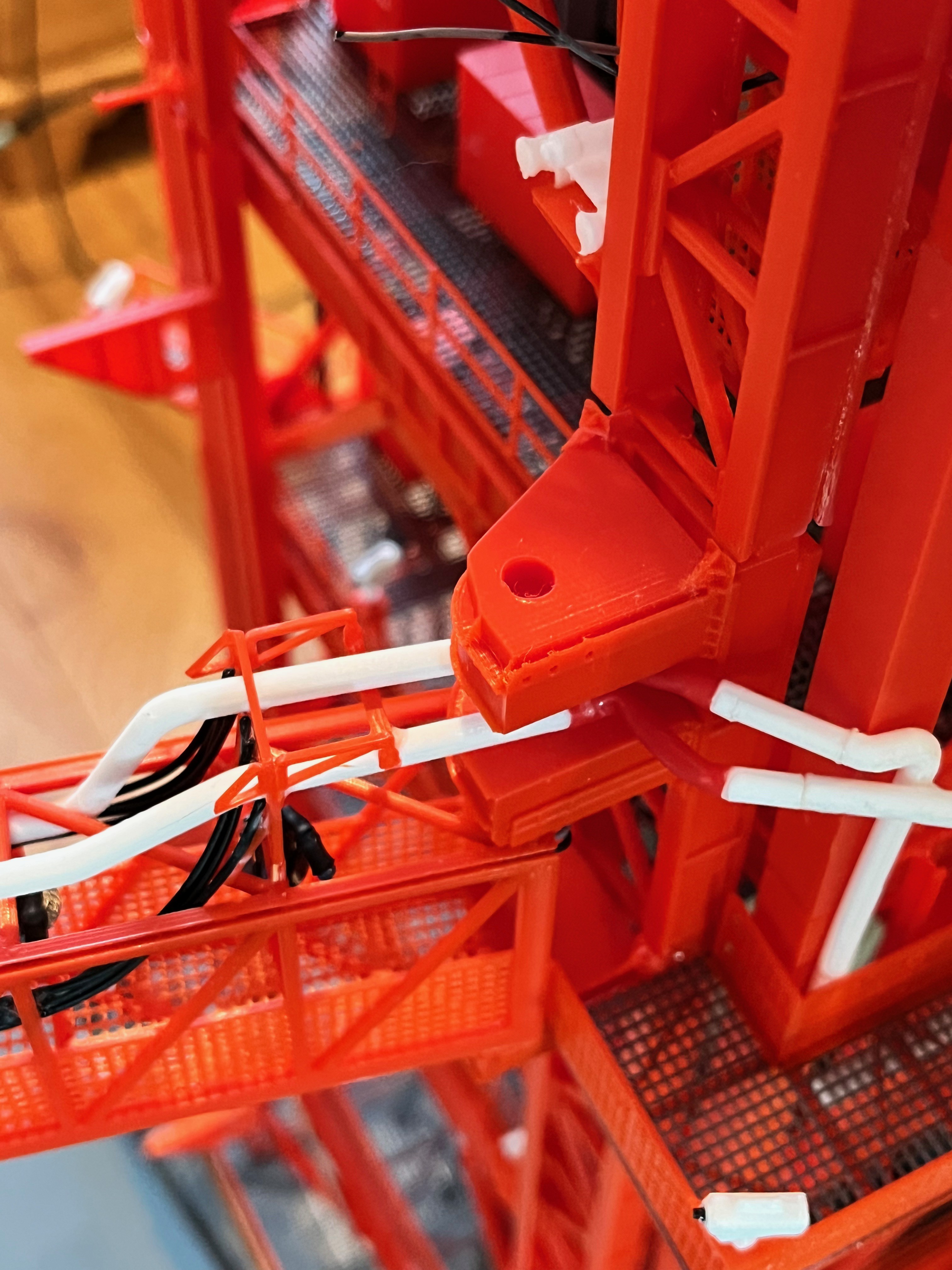
Here are two of the small control panels that are missing from the Aviator67 parts. The SAII Aft Manual Control Panel has three wires, similar to the additions to the Hydropneumatic Consoles.
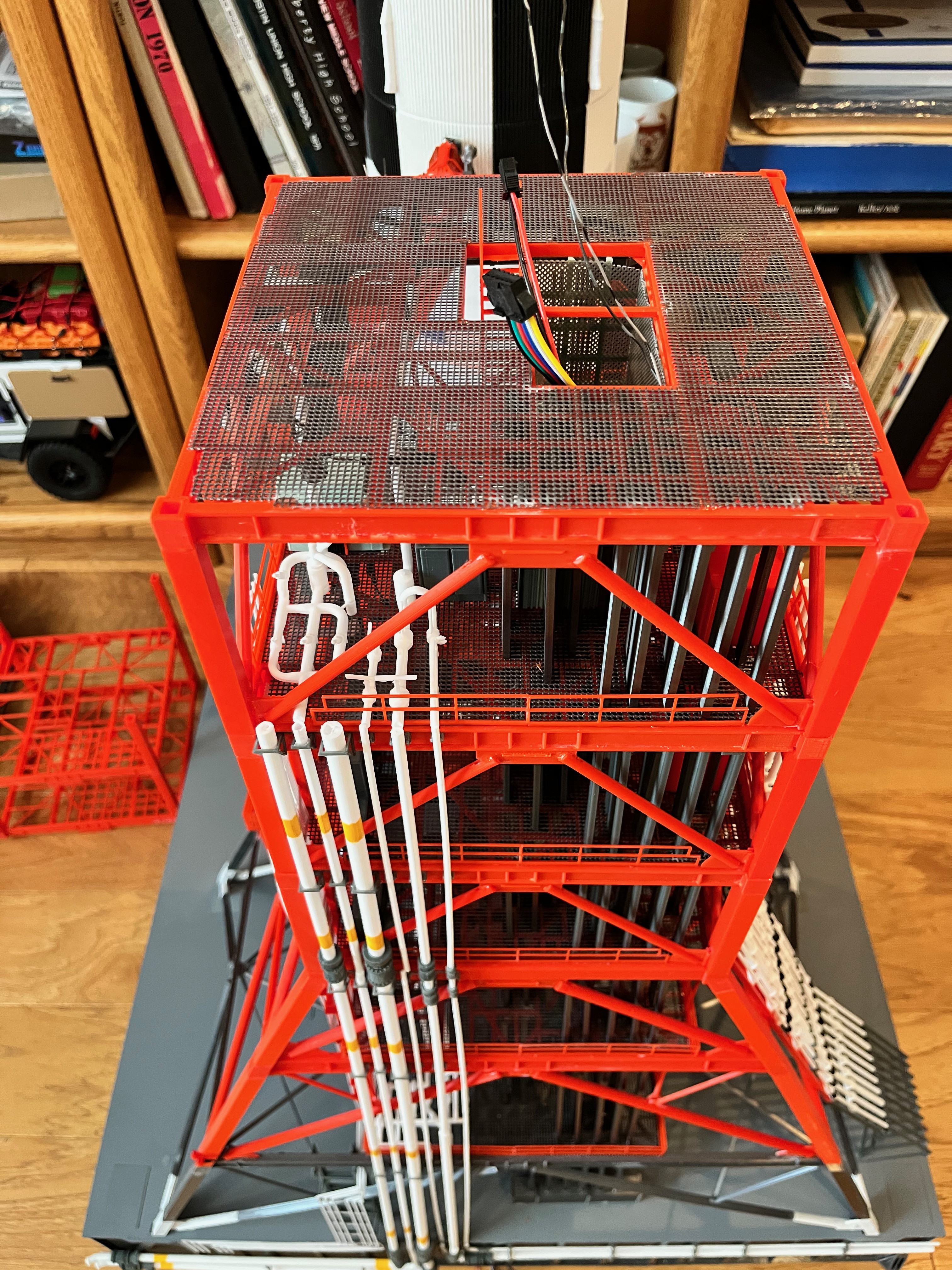
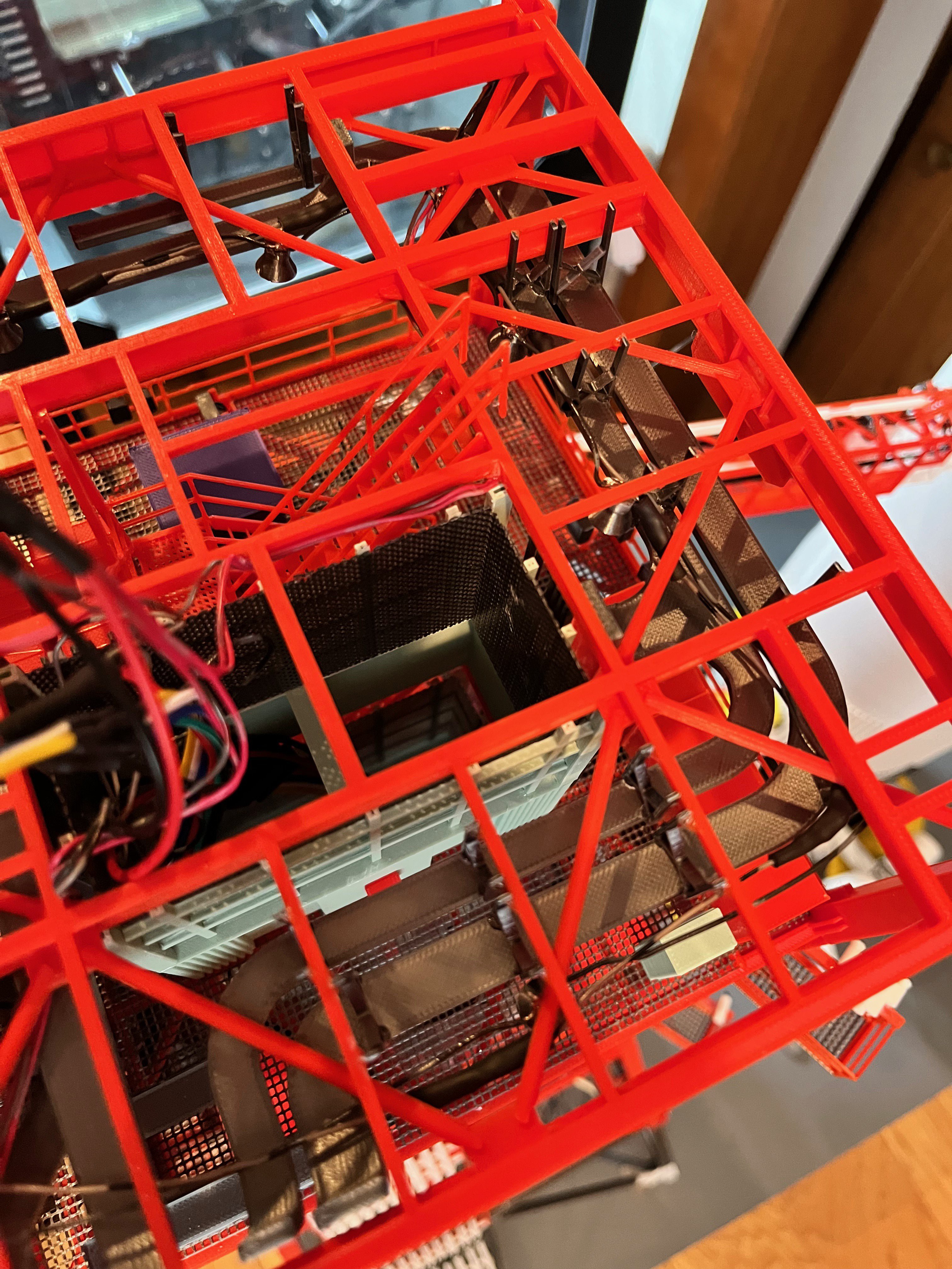
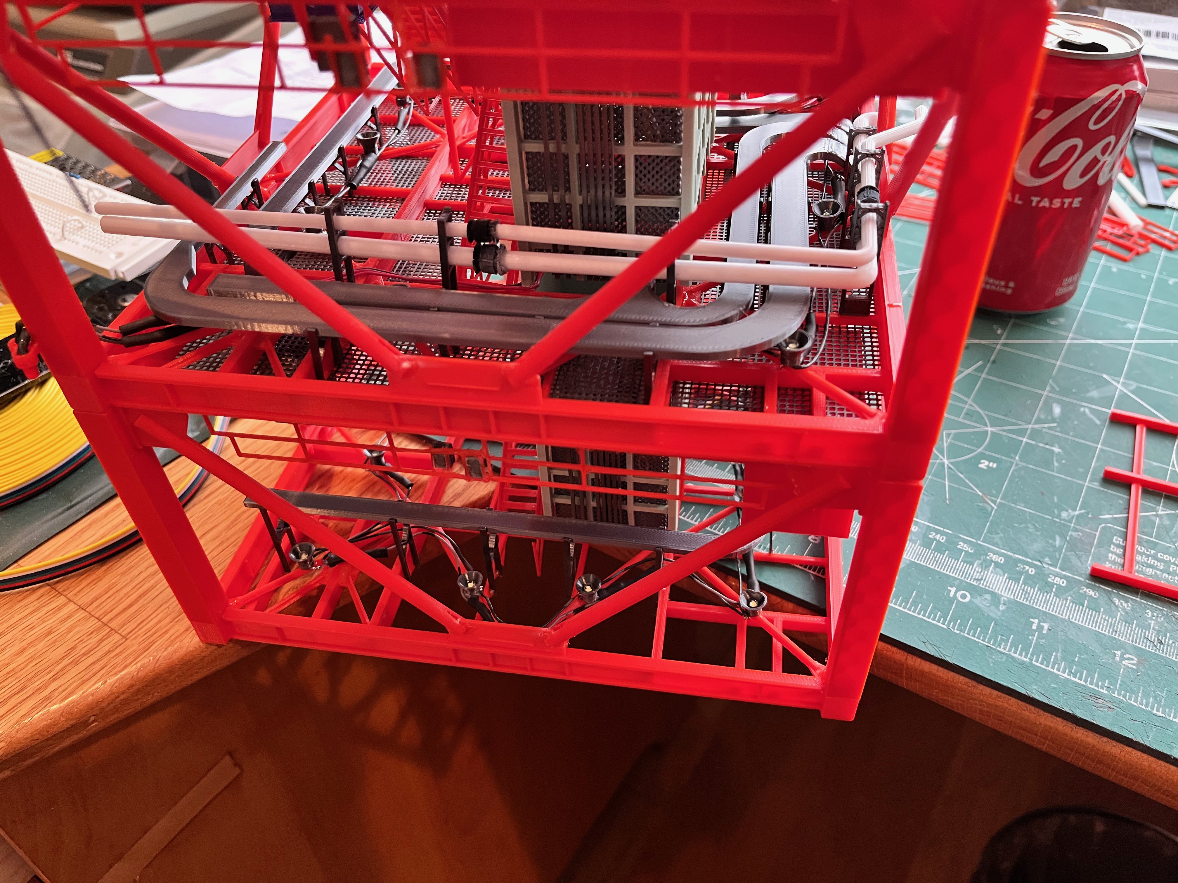
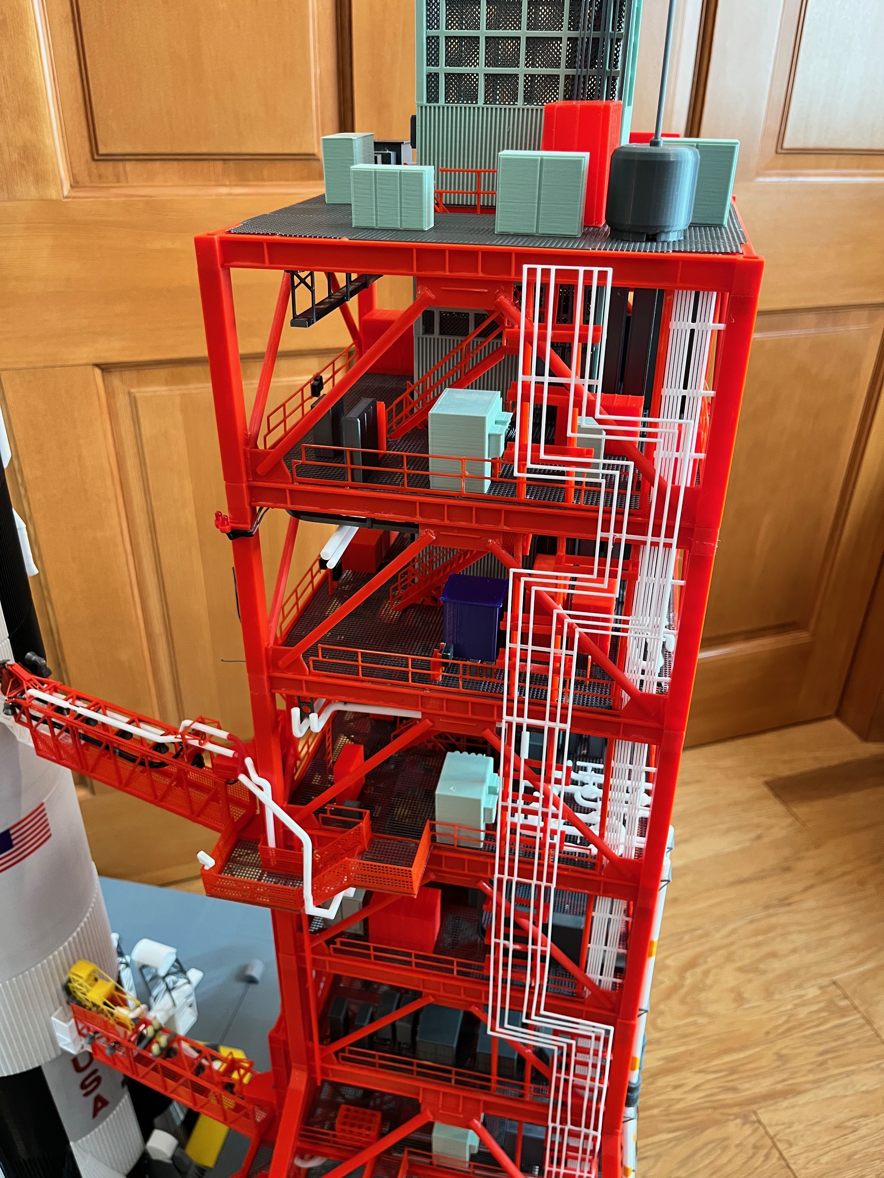
Kind of a busy picture but I have not shown much of the under floor cable trays. This is the cable trays that hang under the level 160 floor. You can see the cable tray hangers. I glue them on with the cable tray in the correct position and then snip off the excess length that sticks up above the floor once the glue dries. I also use the ceiling cable trays held in place with clothes pins while gluing and wiring the lights. The lights go on and then with the floor in place the cable trays go on.
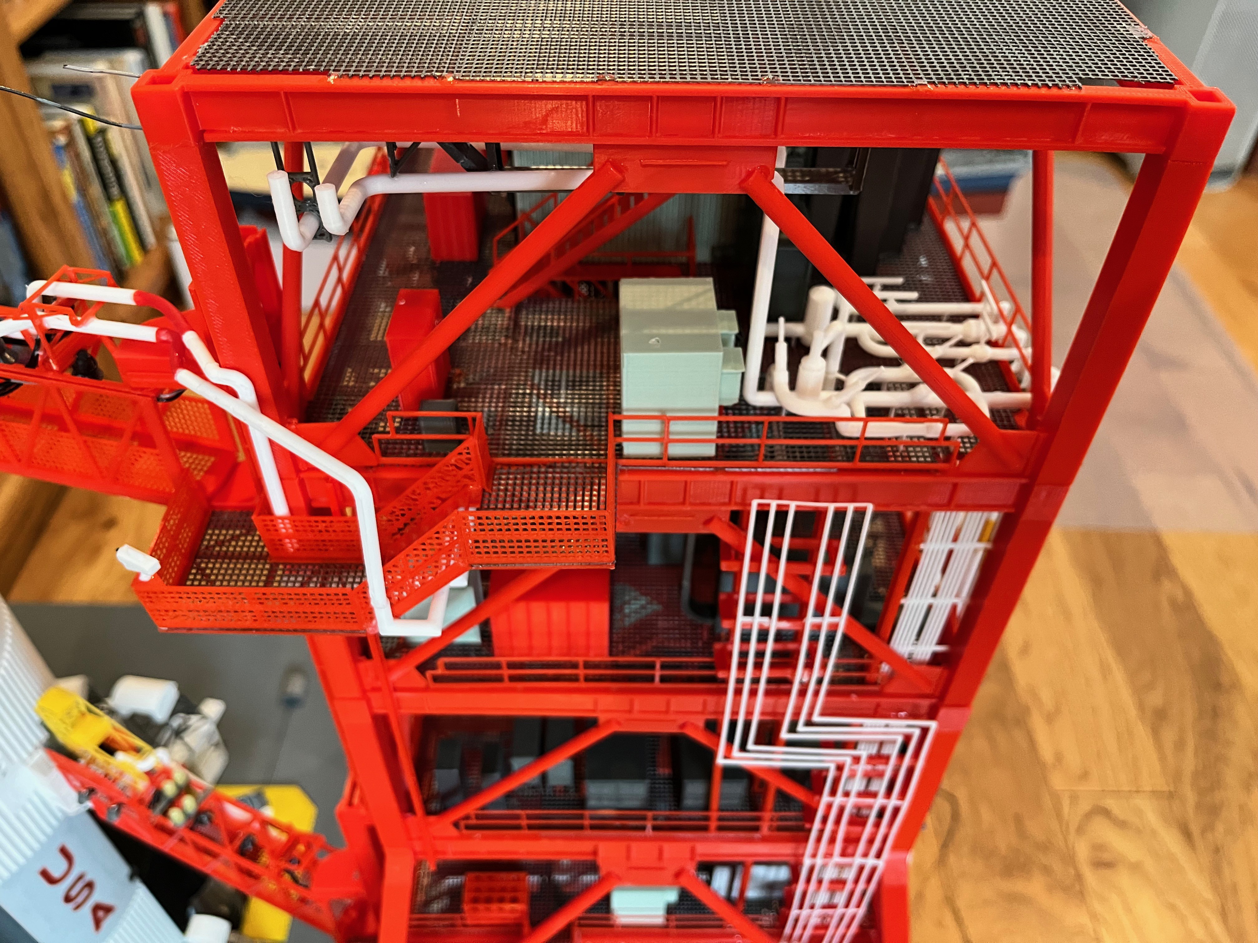
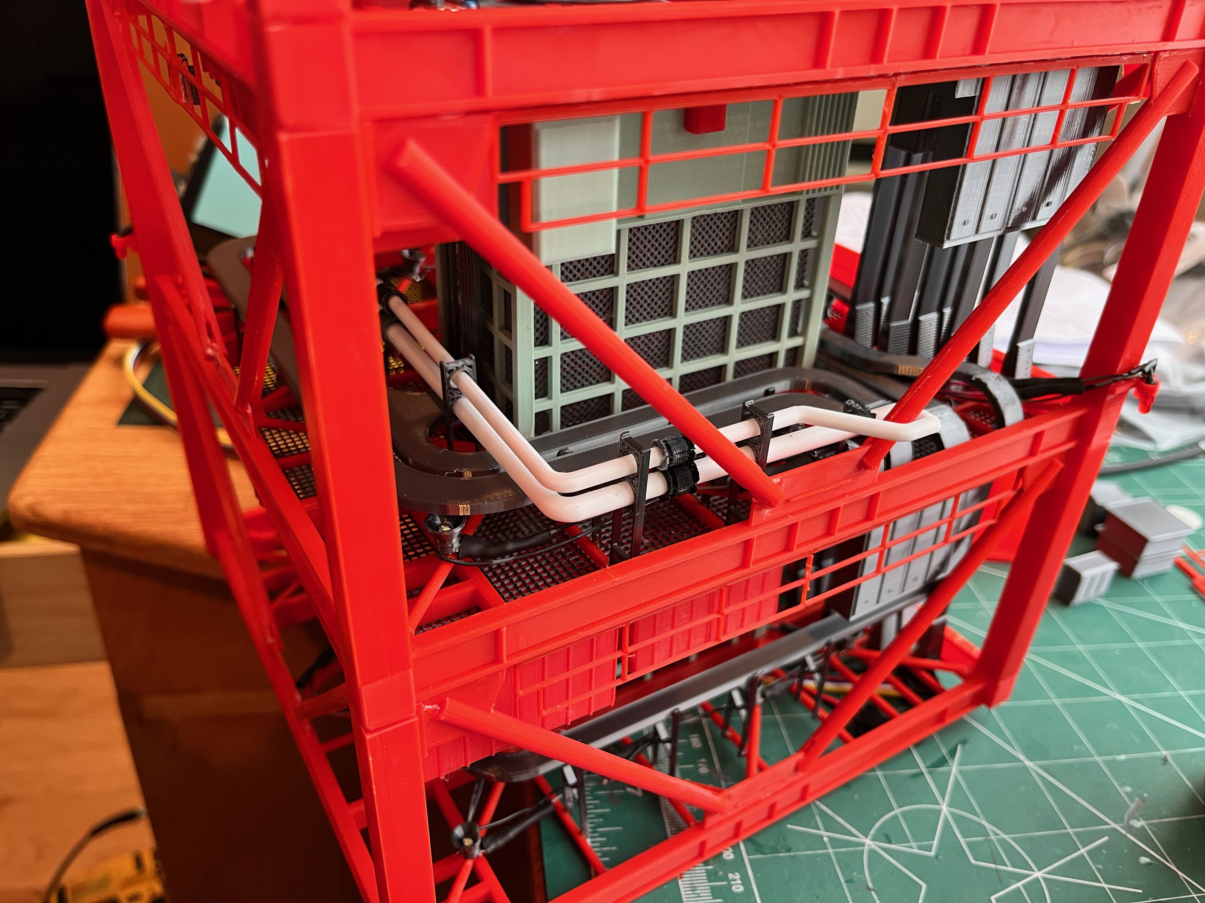
I'm to the point now where I have to stand to add parts to the model. Before long I expect to have to use a step stool. This is a picture of the equipment on level 160.

I'm working on the Level 190 structure that holds pipes. Unfortunately this mid-level is right where removable sections #3 and #4 meet. As a result, part of this structure will attach to the floor of L180 and part will hang from the ceiling of L200. As soon as I print the potion that glues to the L180 floor I will publish all those parts.
On the Printables web site I was asked why there are no holes in the floor gratings for the cable trays. If you remember about a year ago I tried to print the floor grates with holes in them and was not happy with the results. So I decided to print the floor grating without holes. When gluing the next set of vertical cable trays, once the next level structure is on I glue the bottom of the cable tray to the floor grating below and the top to the floor I-beams above. Once all the cable trays, both vertical and horizontal are glued in along with the stairs, I then glue the upper floor grating on. For the cable trays at the removable section breaks, the cable trays are glued to the upper floor I-beams and not to the lower floor grating. This allows the sections to be removable.
As an example, assume I have already glued on the elevator and equipment that sits on the L160 floor grating. I then glue on the structure for Level 160-180. Next up is the stairs which are glued to both the L180 floor I-beams and the L160 floor grating. Then the vertical cable trays are added. The bottom is glued to the L160 floor grating and the top is glued to the L180 floor I-beams. After that the horizontal cable trays are added as they are typically glued to one or more vertical cable tray. The tray hangers are made intentionally long so that the cable tray can be positioned and the excess length is cut off once the glue dries. Now the L180 floor grating can be glued on top of the L180 floor I-beam structure.
I hope this helps. The model is so complex, creating a step by step instruction manual would take thousands of pages. Once you get started you will notice the steps become repetitive.
At L140-160 there are ECS pipes that run under the ceiling over to Swing Arm #4. I forgot to add these when it was easy. This will now test my skills at adding pieces in tight spaces. Fortunately I can remove this section of the tower and add the pieces with this section upside down which should help. These pieces have been added to the spreadsheet and the Pipe Side 2 model.
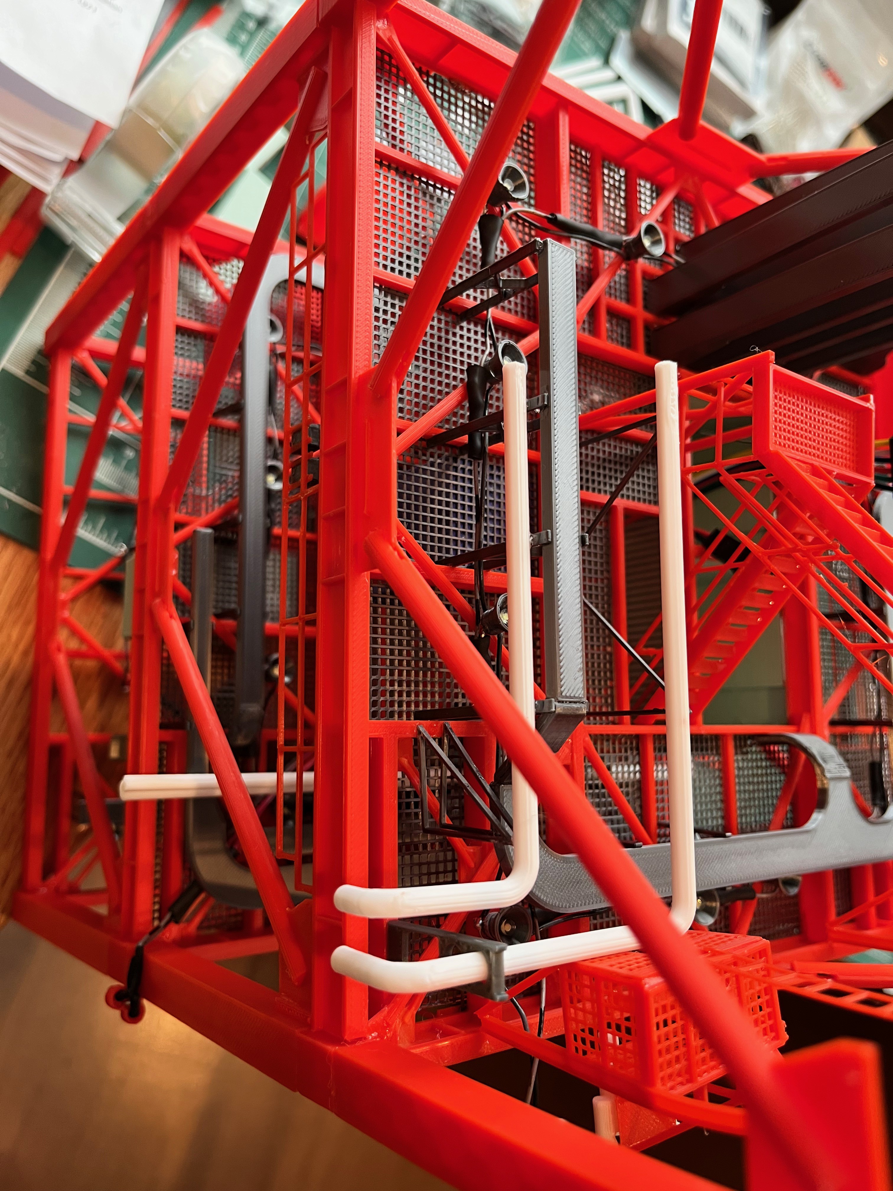
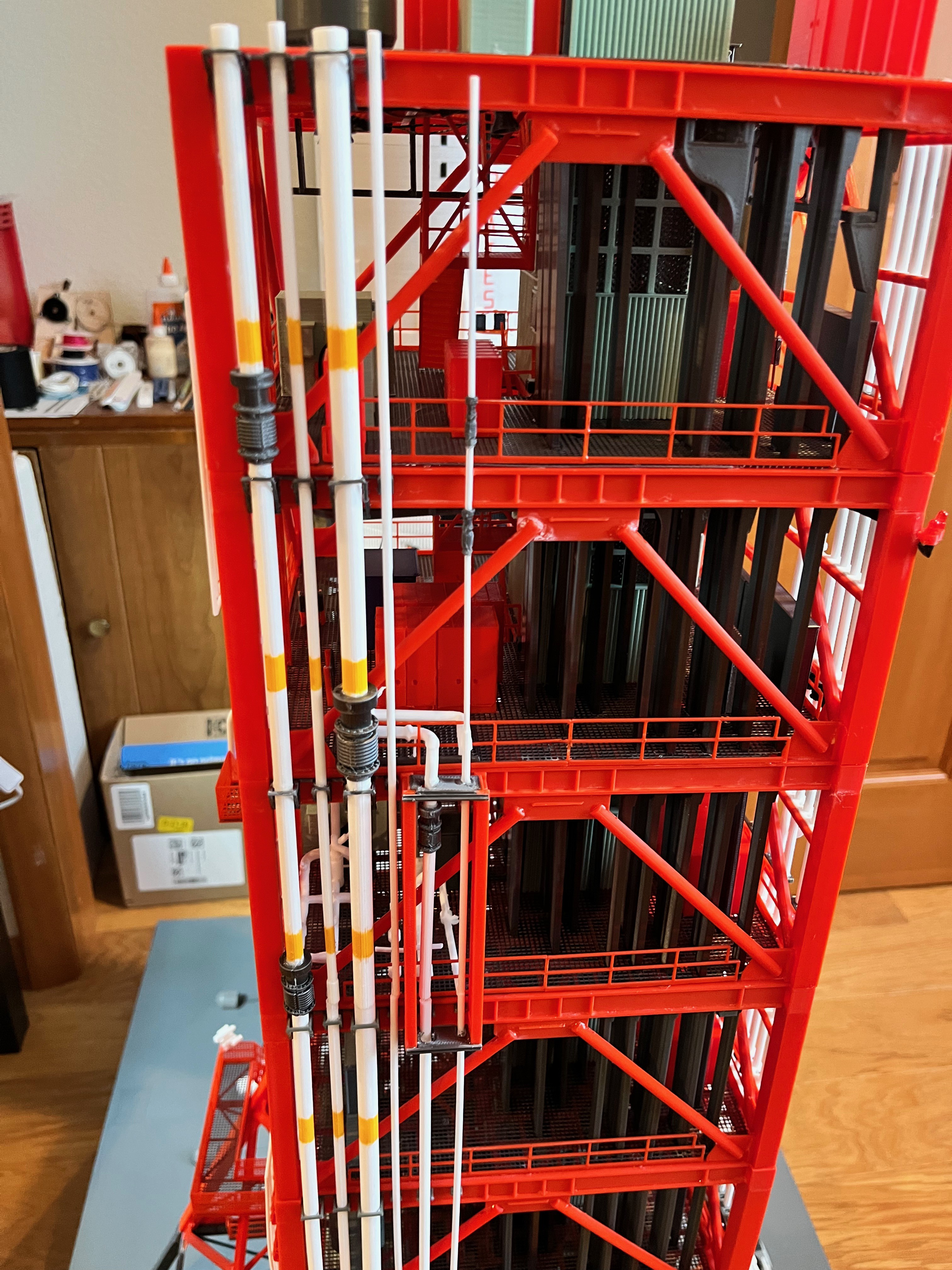
Here are the E5/6 pipes running along the ceiling just under the cable trays, the ones I forgot to add when access was easy. This was fairly easy with section #3 of the tower removed and upside down.
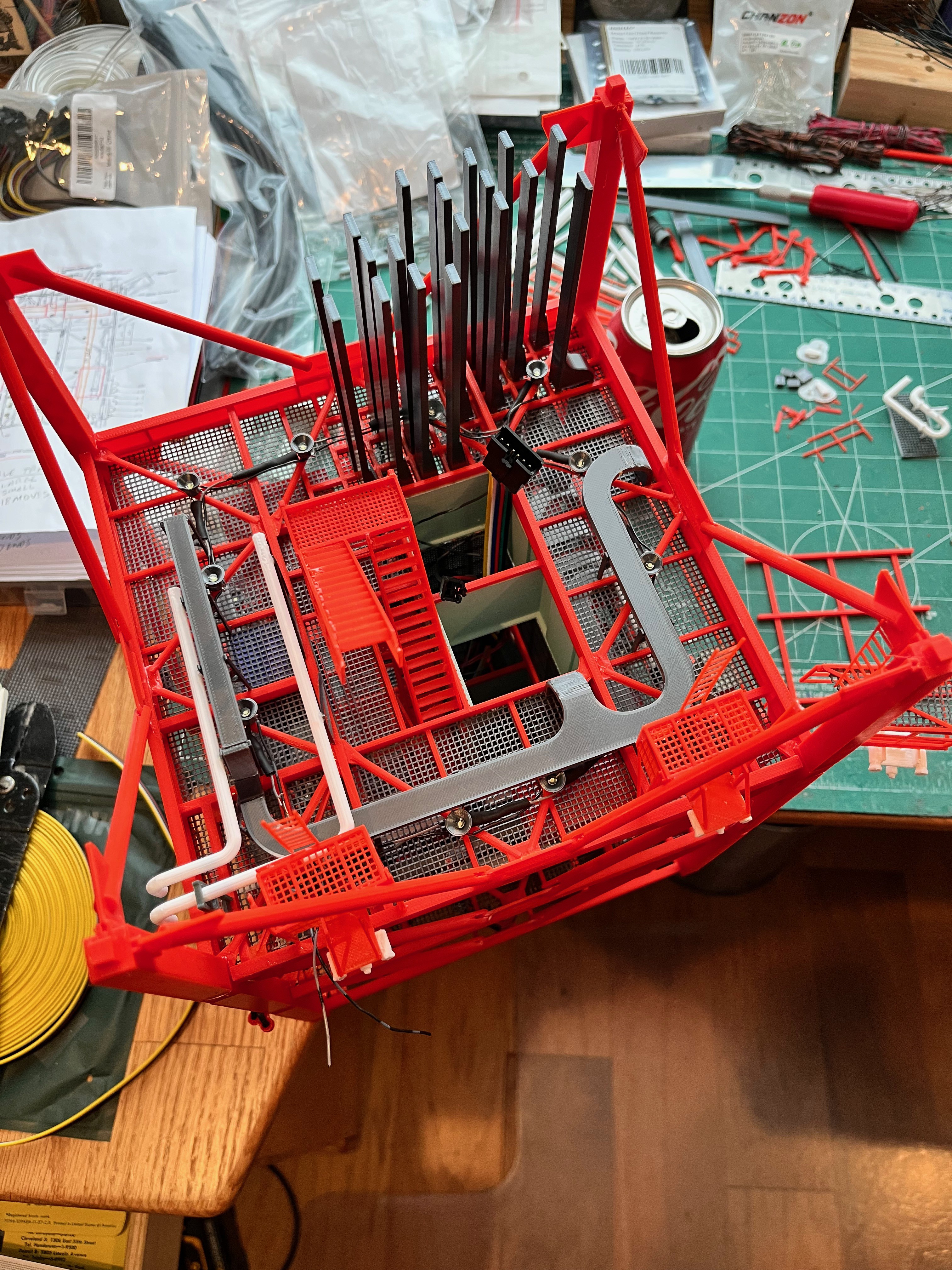
And here are more pictures of Section #3 upside down. You can see how the stairs and cable trays hang from the underside of the ceiling for these removable sections. The elevator is glued to the top of the previous section. The pipes for this level hang via some delicate brackets that are much easier to access while upside down, however I glued them on while the first floor of this section was in place so I could line up the pipes with the previous section.
The original Aviator67 Side 2 Frame Cabinets had some seemingly extra boxes I wasn't using so I removed the lower boxes. The cabinets with attached cables look great! There are two types of cabinets. I have put these modified cabinets at L120 and L160. The spreadsheet of parts has been updated, hopefully correctly and the two new parts have been added to Printables.
Section 3, Side 2 pipes complete. I feel like I am reaching Max-Q, the progress is slow but as the pipes end I realize the higher you go, the less parts there will be per floor so I should start gaining speed.

Here is the equipment glued to the L180 floor. I still have to add the lower part of L190.
Section 3 Side 4 pipes complete. At each level there are three small vertical I-beams. I did not create these, but copied them from the Aviator67 support structure on Side 2. These are not the way I usually split I-beams where the seam is visible, but it saves me some work and two of the parts are hardy visible. There are also three stand-offs per level. The lower one can simply be glued on. The other two wrap around the floor cross brace. For these I use a sprue cutter to nip away at the backside to get them to fit around the brace. Many of these parts require a little fitting on your part. These stand-offs should line up with the hydraulic pipes. Your fitment may vary.
Section 3 Side 3 pipes are complete. Another pipe ends and two taper down. Notice that there is an interesting pipe support for the LOX pipes.

Section #3 Side 1 support and locking columns are on. I even added the camera on a pole at level 160. That makes 16 cameras so far. Why a camera on a pole? Because apparently you can't have enough cameras.

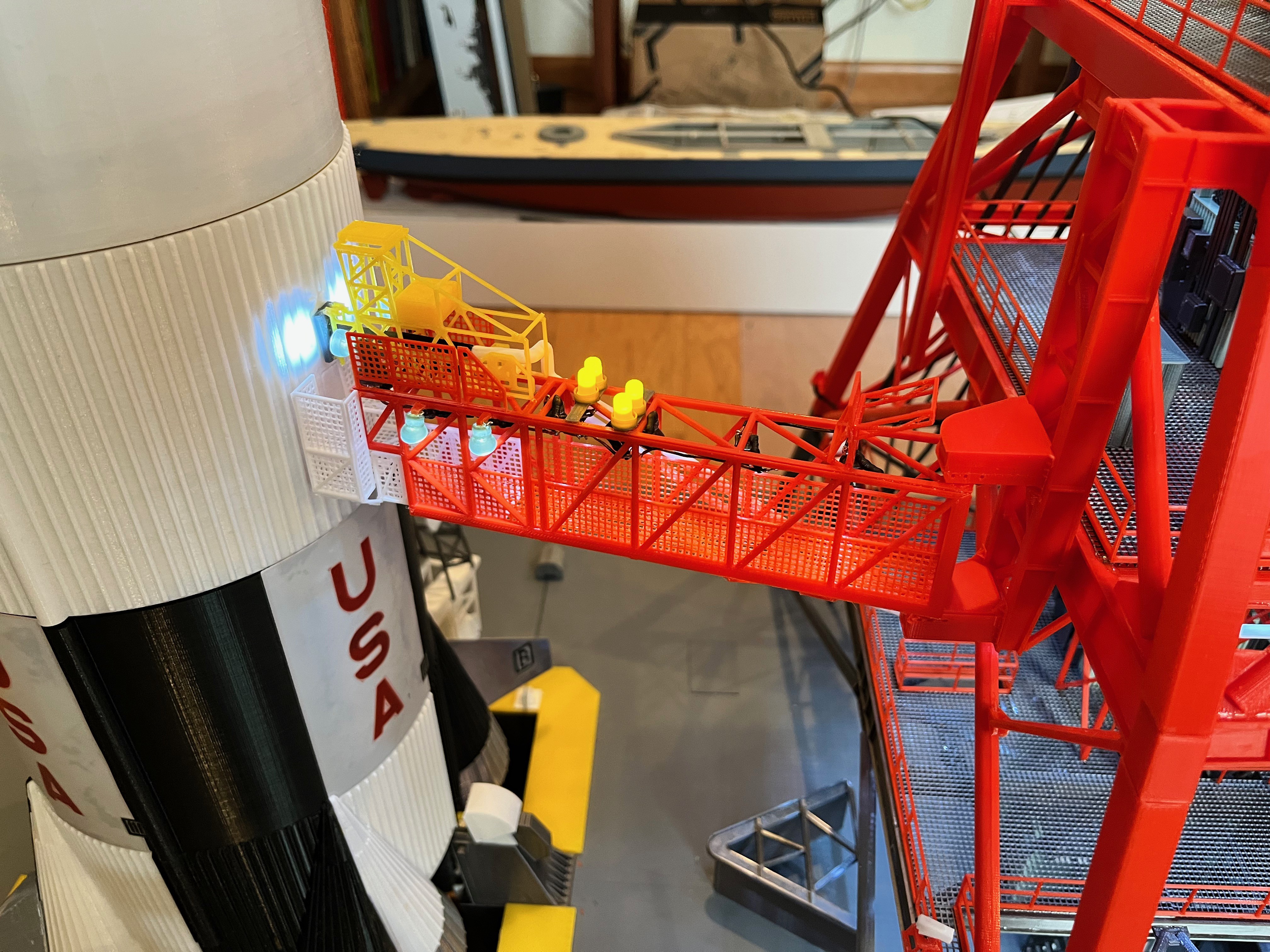
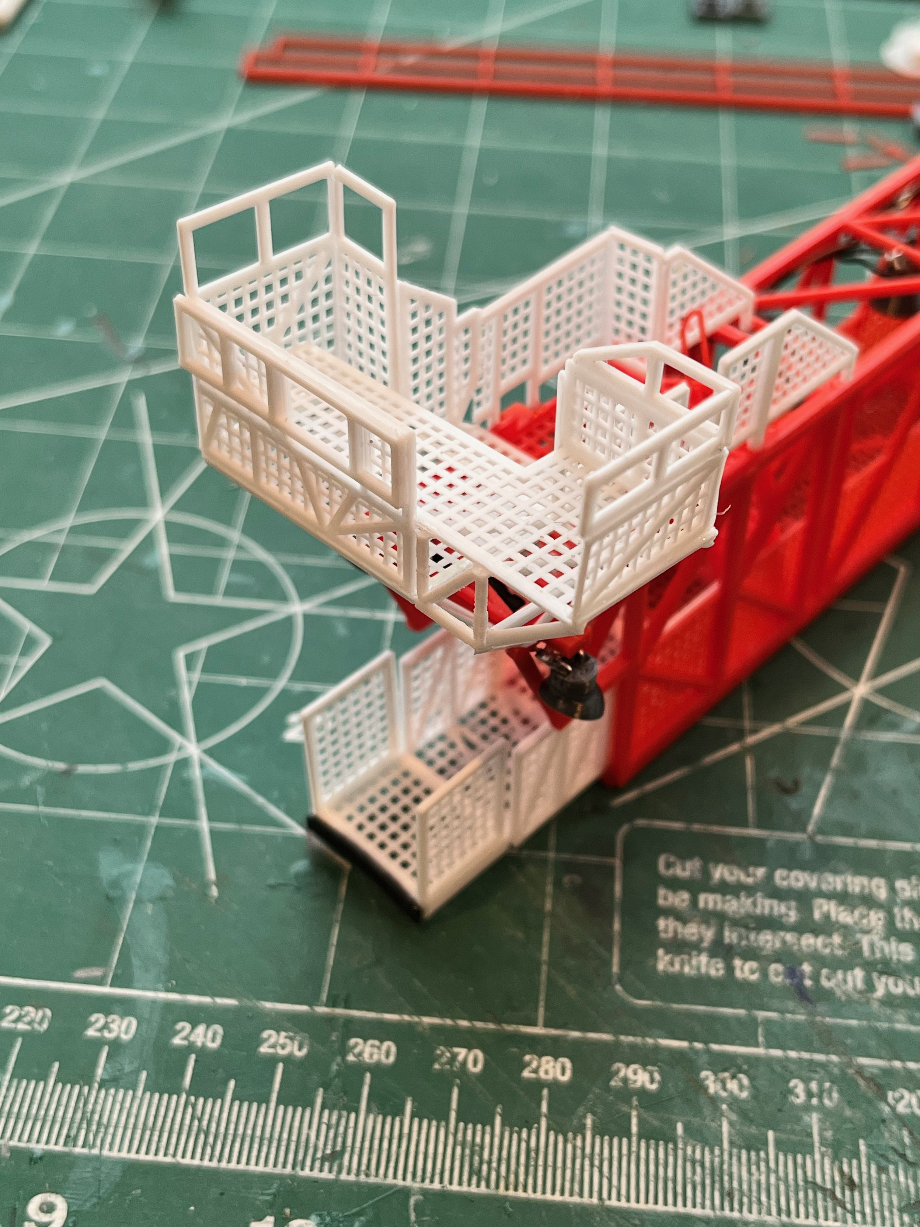
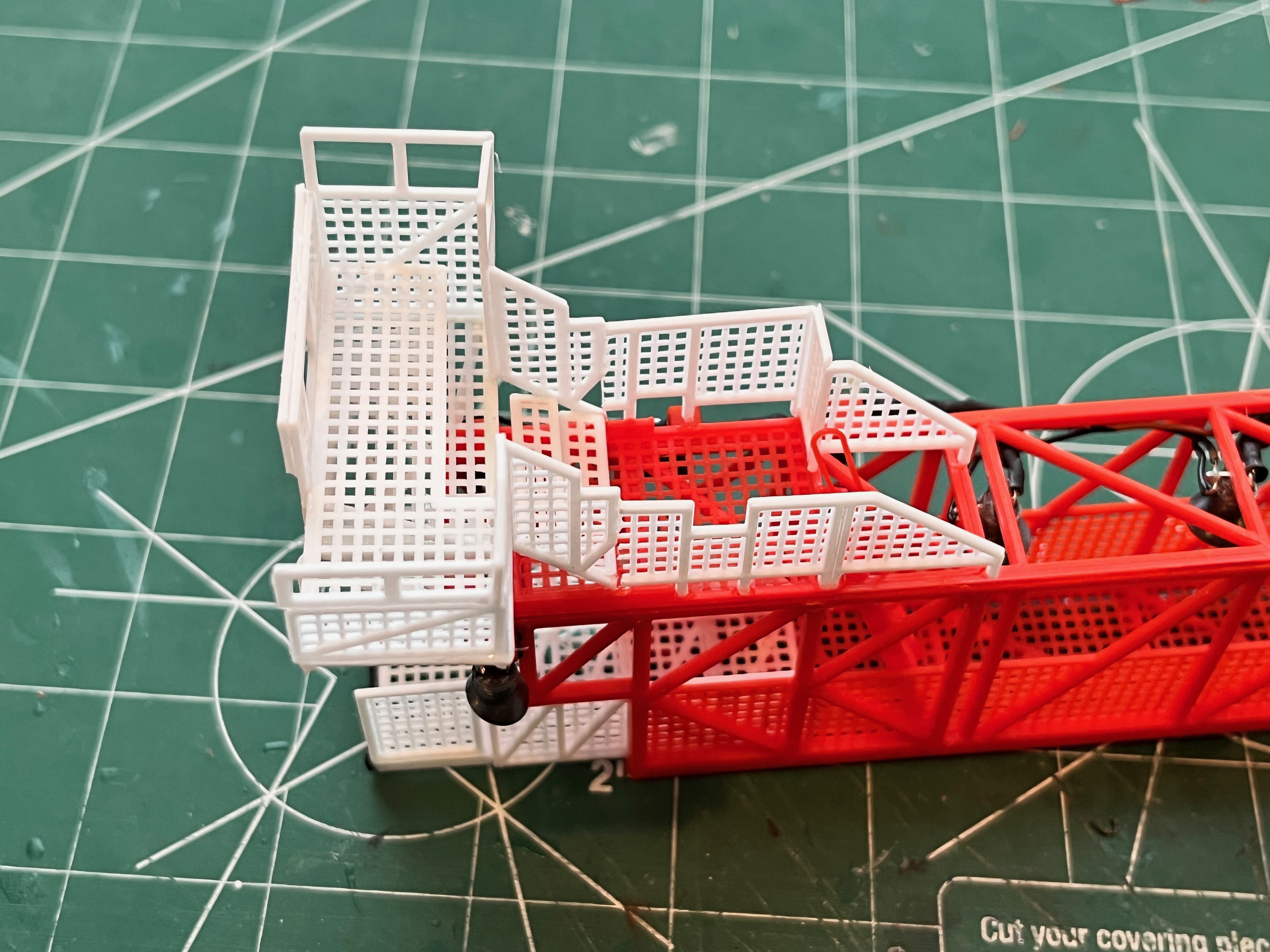
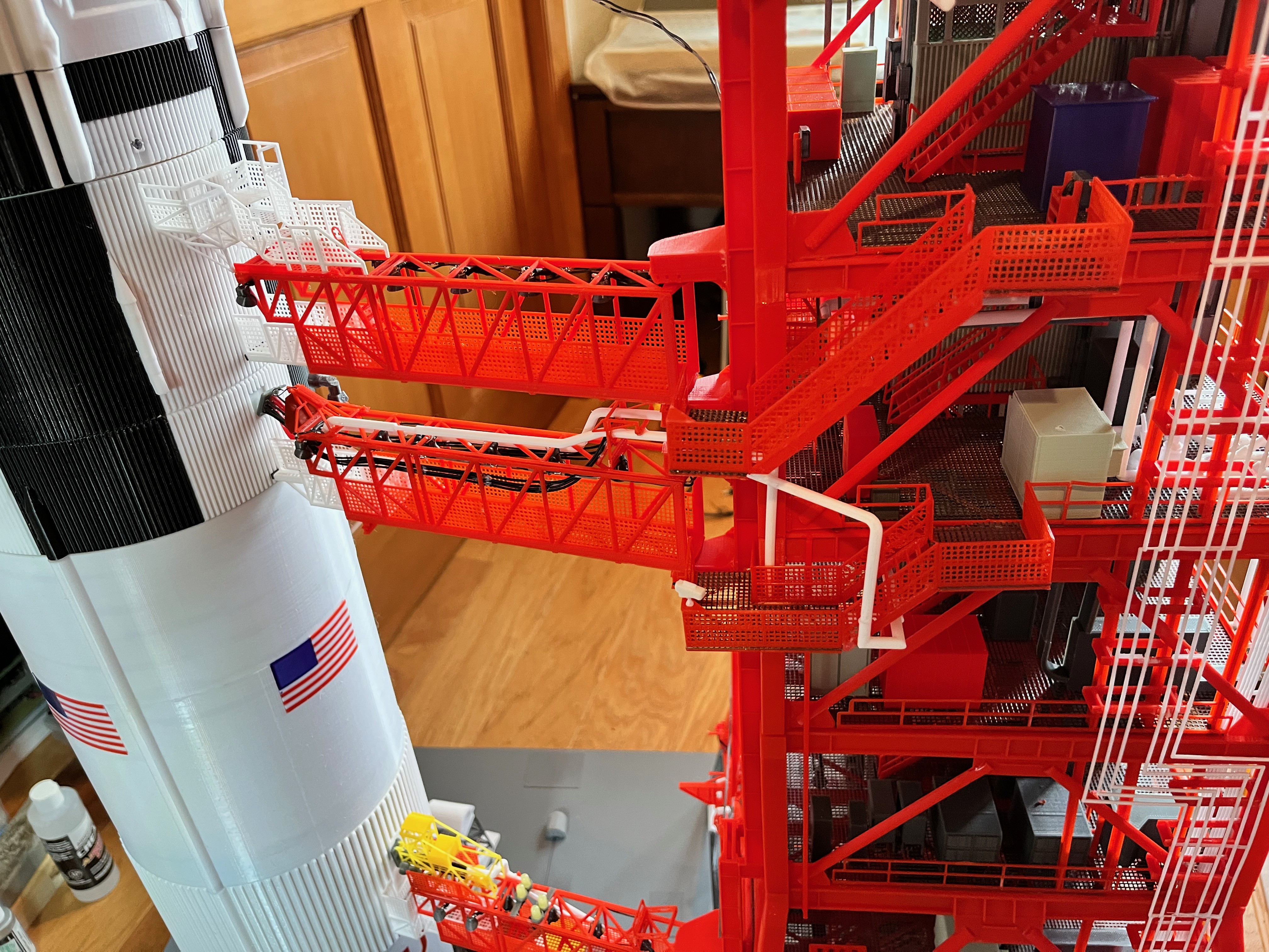
Swing Arm #3 is built and ready to attach. I'm happy with the way the end platform went together. There are many ways to configure the walls of the upper platform as the upper wall parts can be folded down (I only folded down the front portion) and the walls can even be laid flat. This arm was easy because there are no pipes. I did have to trim the lower side panels just a little to get the length correct. You can see this in the side/top perspective picture. I glued those side panels on then glued up the rest of the upper platform as a separate unit and then with the arm in place positioned the upper platform to decide how much to trim.

The one issue that is not really an issue is the position of the lower hinge for this swing arm. The removable sections of the tower alternate between two and three floors. The support columns however have a length of 2.5 floors. This is so that these parts are all the same length and they just fit on the print platform diagonally. This means that the second removable section has a support column that sticks up half a floor level (10 feet) above the top floor. This allows swing arm #2 to be fully attached to the second section. It turns out swing arm #3 spans sections 2 and 3. The lower hinge just fits onto the support column for section 2 (see picture below). The upper hinge will glue to the support column above (the one attached to the third section). This is OK because if I ever disassemble the tower, the swing arms will first be swung against the tower and tied in place with string or twisty ties. Swing arm #3 will also need to be tied at the hinges to the third section. Once removed this arm will only be attached to the upper hinge.
BTW, here is another source of pictures and drawings with dimensions for the swing arms: https://www.apollomaniacs.com/apollo/mob..._and_Access_arm
Swing Arm #3 complete! By far the easiest of the swing arms. The files for this arm have been published. I still need to add the camera to the walkway.


Level 190 is split into the lower section that is glued to the L180 floor as shown in the picture below. The L190 upper section will be glued to the ceiling of L200.

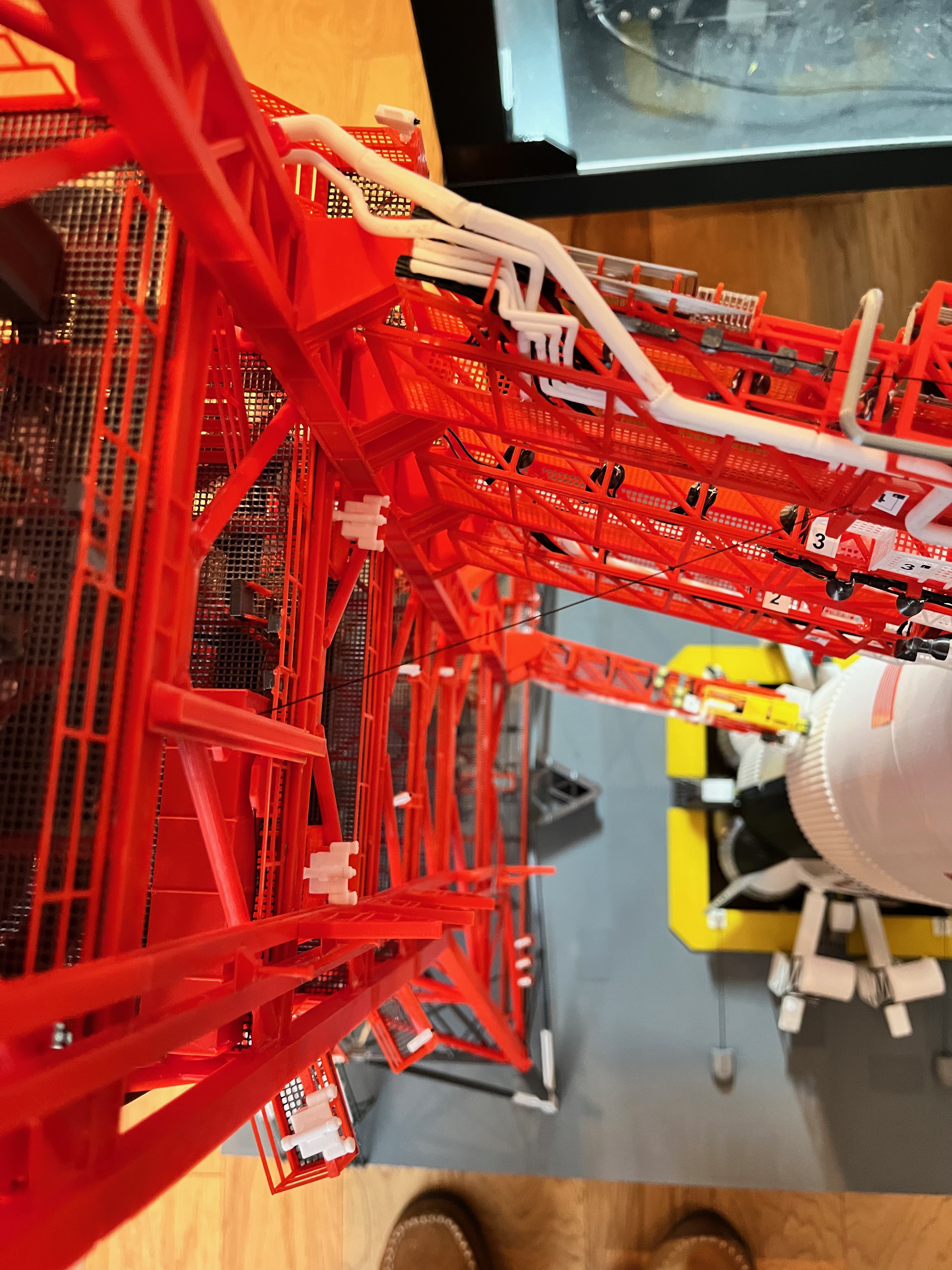


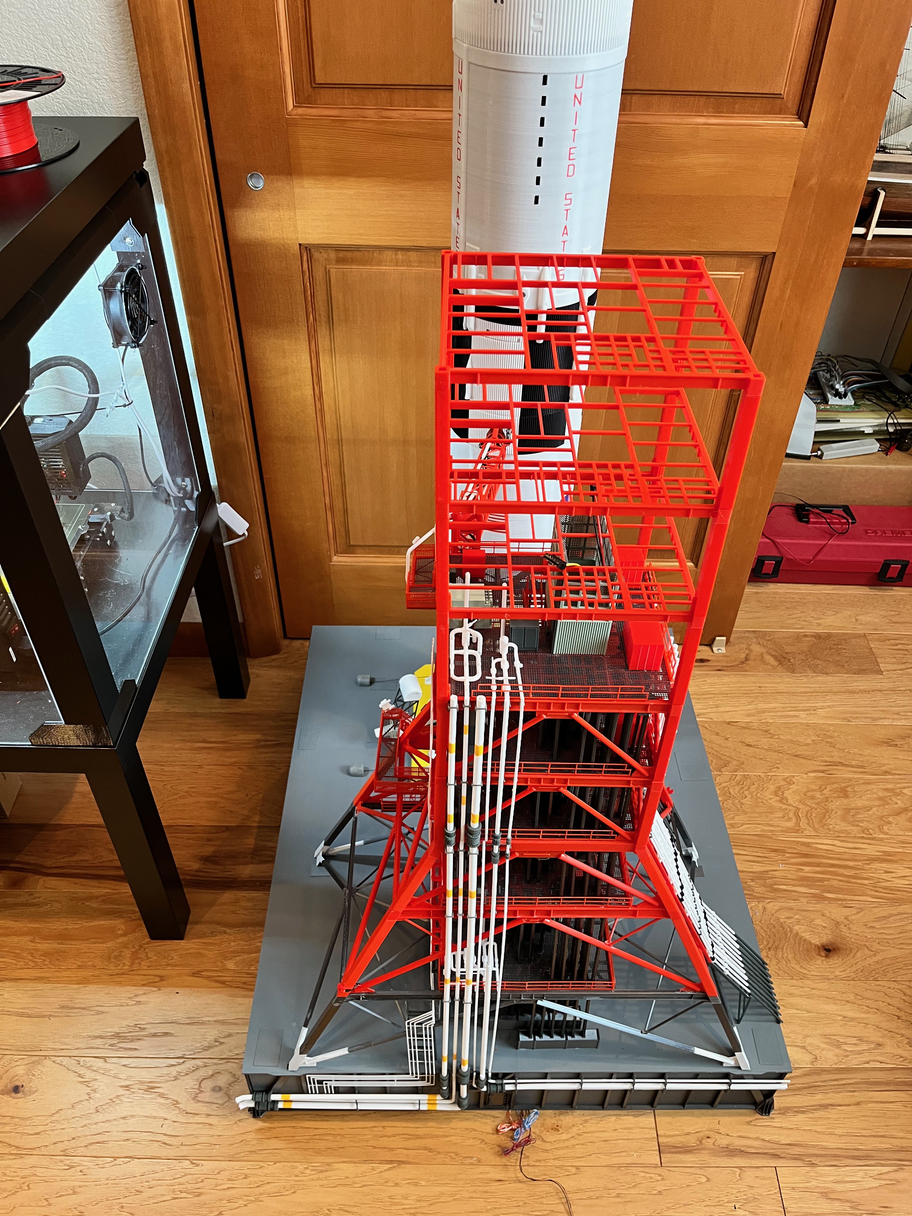
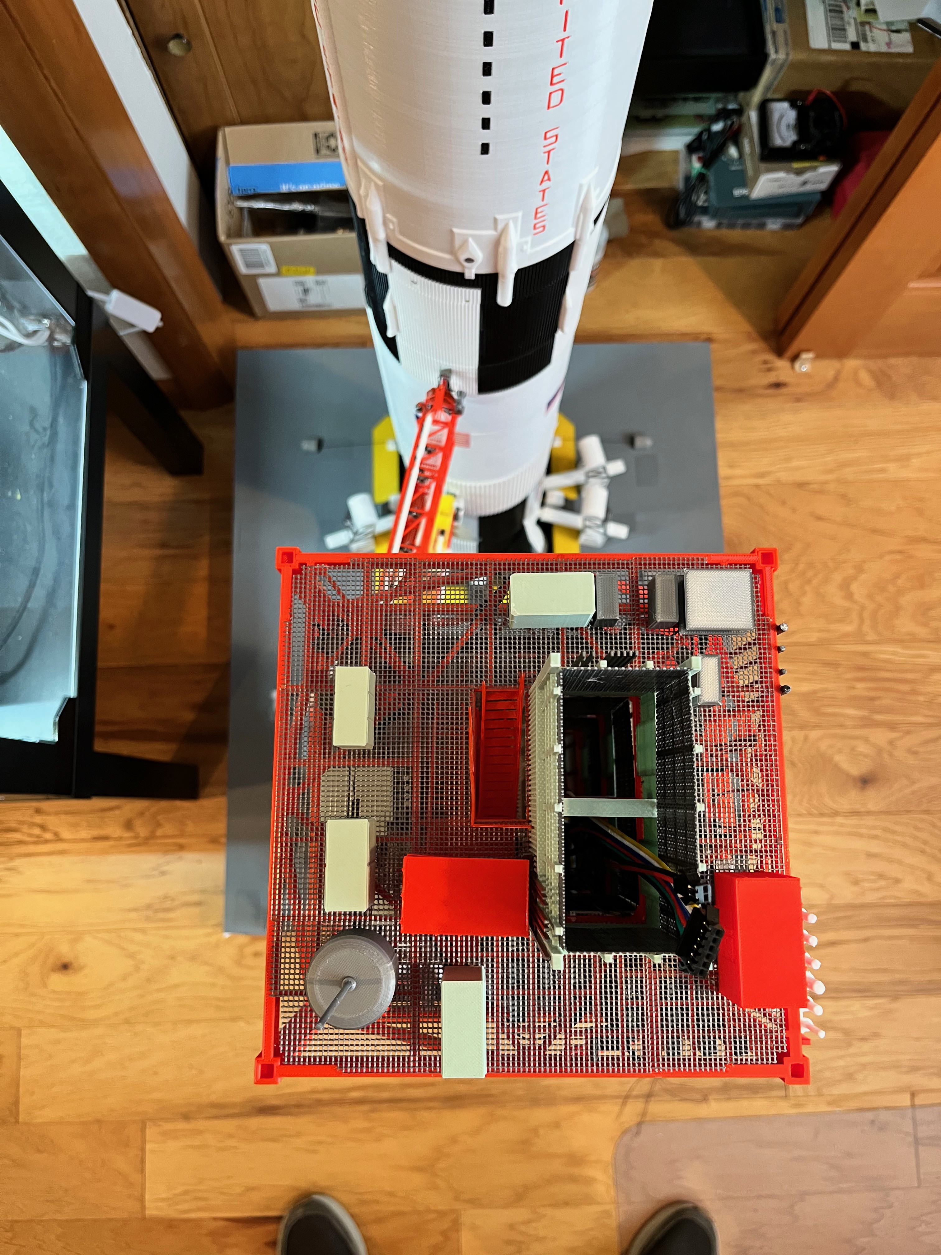
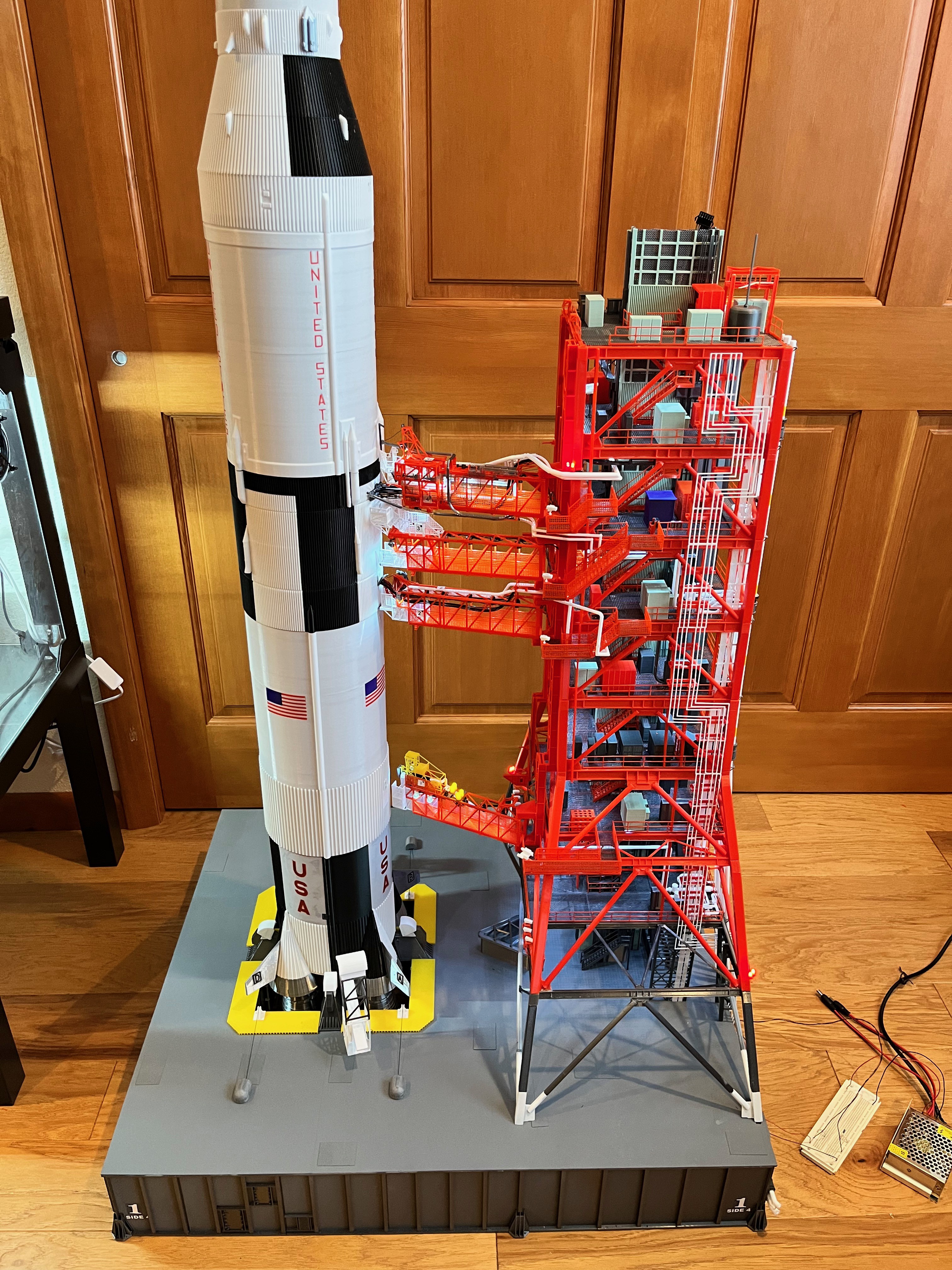
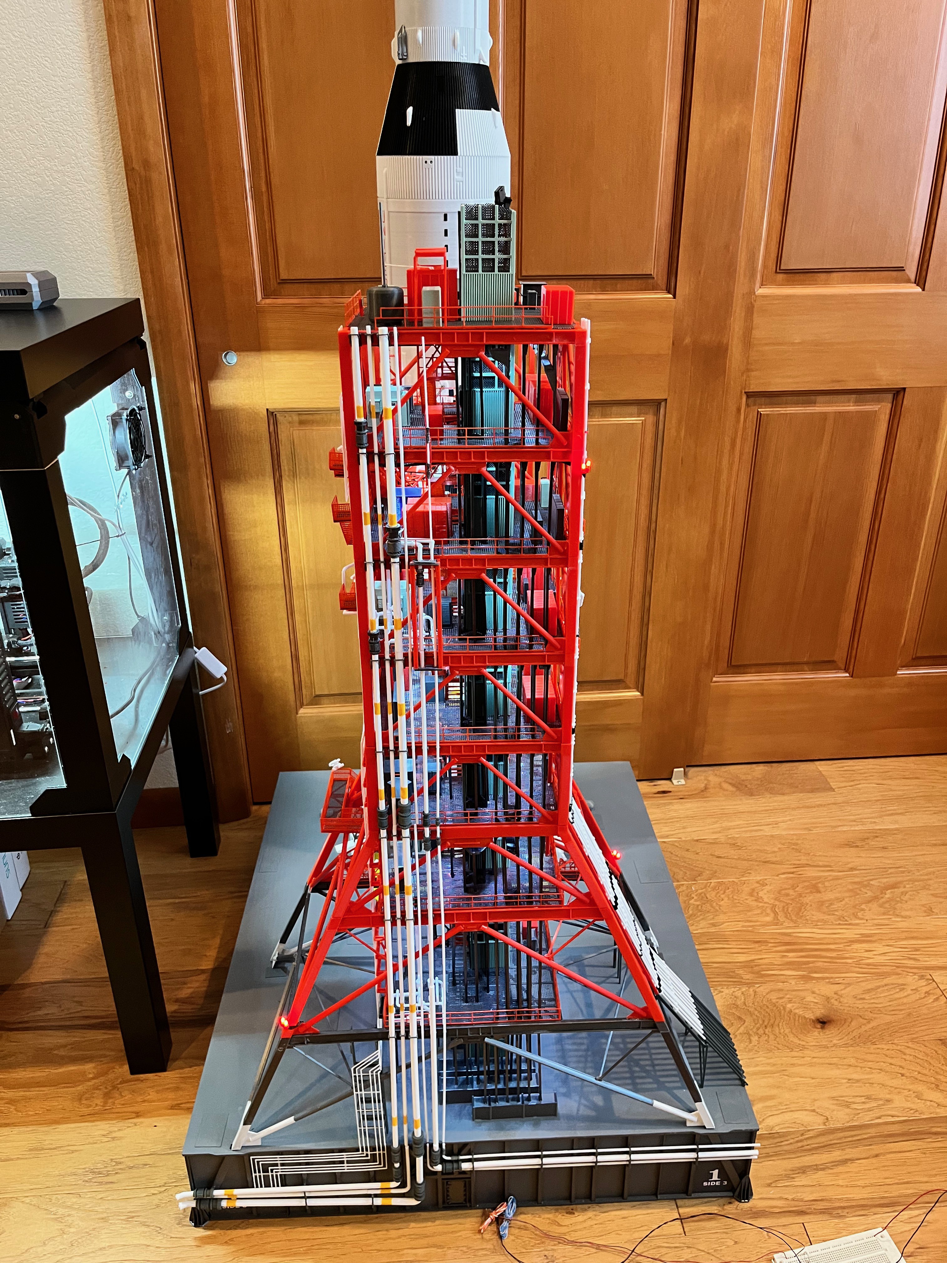
Section #3 of the tower is now complete! This is a significant milestone because this is up to level 180 which means the tower is half complete, at least in height. Here are pictures of sides 2, 3 and 4 with the lights on along with an overall picture of the entire model.


Discussions
Become a Hackaday.io Member
Create an account to leave a comment. Already have an account? Log In.