Bo Yao
-
Build the Wooden Keycap
12/30/2023 at 16:24 • 0 commentsIn this blog post, we are going to build the wooden keycap!
Review possible approaches
You probably already familiar with a mechanical keycap. It is usually a thin, box shaped but with curves. On the backside, it has a cross shaped connector to fit the key switch slot. There are several possible ways to build it, with wood:
- Carve the front side and the back side of keycap manually
- Carve the back side with a 2D CNC cutter and the front side of keycap manually
- Carve both side with a 3D CNC machine
- Carve the front side with a 3D CNC cutter and 3D print the cross shaped connector part, then glue the connector to the backside of the keyboard.
Each method has certain advantages. I started from method 1, carving manually. Due to my poor sculpting skills, it took more than an hour and the resulting shape isn’t very satisfactory.
Carving the front side, with some practice, is not very difficult and one keycap shape can be make within 20 minute. But the back side hole and the cross-shaped connector is really hard for manual carving. Especially the cross-shaped connector, which needs to be very precise (0.05mm) to fit the mechanical switch. If you have a CNC machine, you can create the back side connector with 2D CNC in seconds. A 2D CNC machine is less expensive than a 3D one. This is the method 2. Therefore if you are good at carving the shape, it can be a good option as well.
If with a 3D CNC machine, you can also carve the shape of the keycap, but 3D carving is much slower than 2D carving and not much faster than manual. This is the method 3 and it took about 10 minutes.
Finally the method 4. If the 2D CNC or the material of the wood cannot fit mechanical switch precisely, or the good product rate too low, you can also only dig out a big rectangular hole on the backside the keycap. And 3D print a cross-shaped connector with ABS or PLA, and glue it to the back side of the keycap.
My build
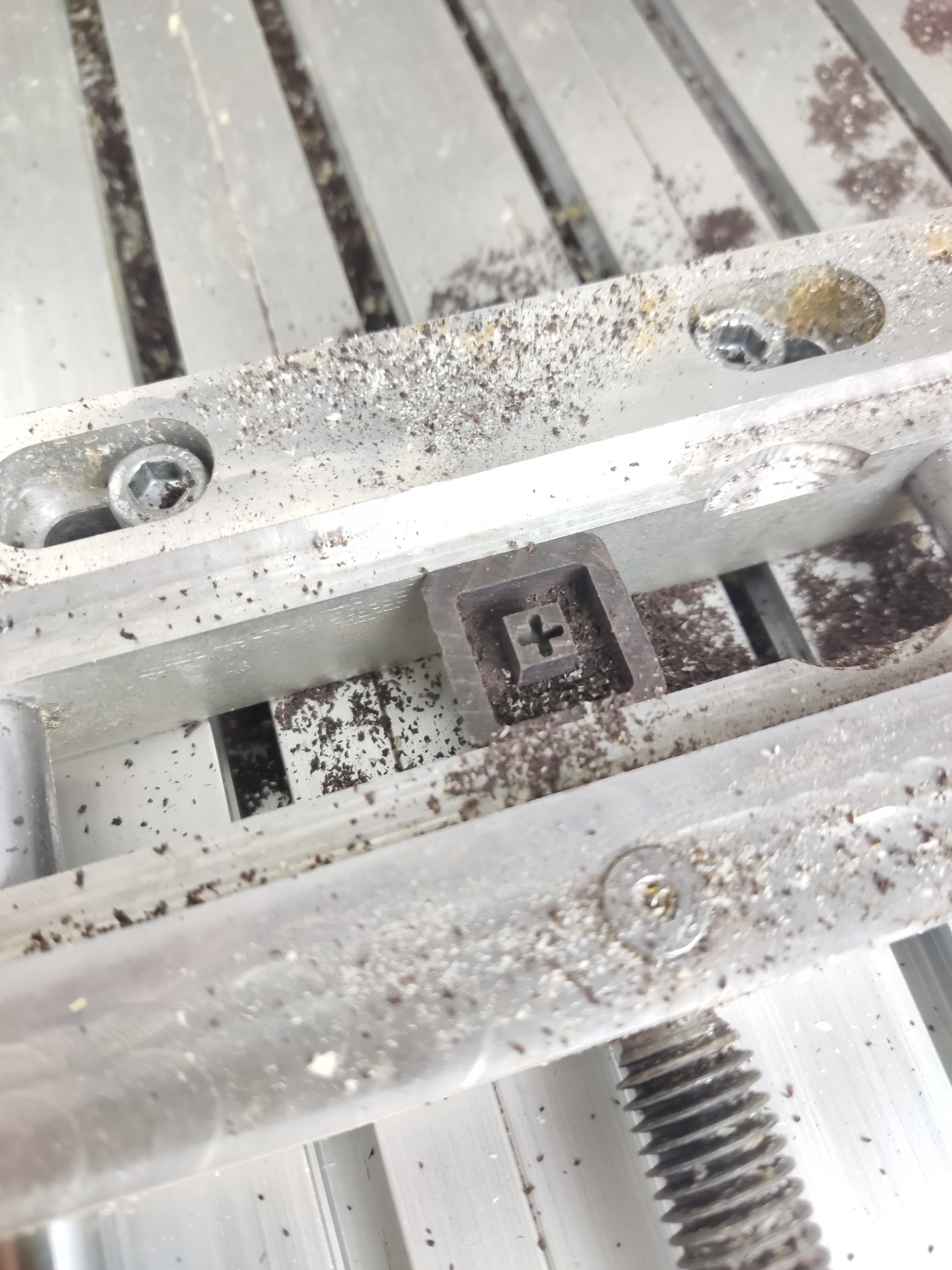
I tried out method 3 and 4, and end up with method 3 because carving the back side connector also result in acceptable good product rate. Here is some shots of the CNC cutting:
The front side:
The back side:
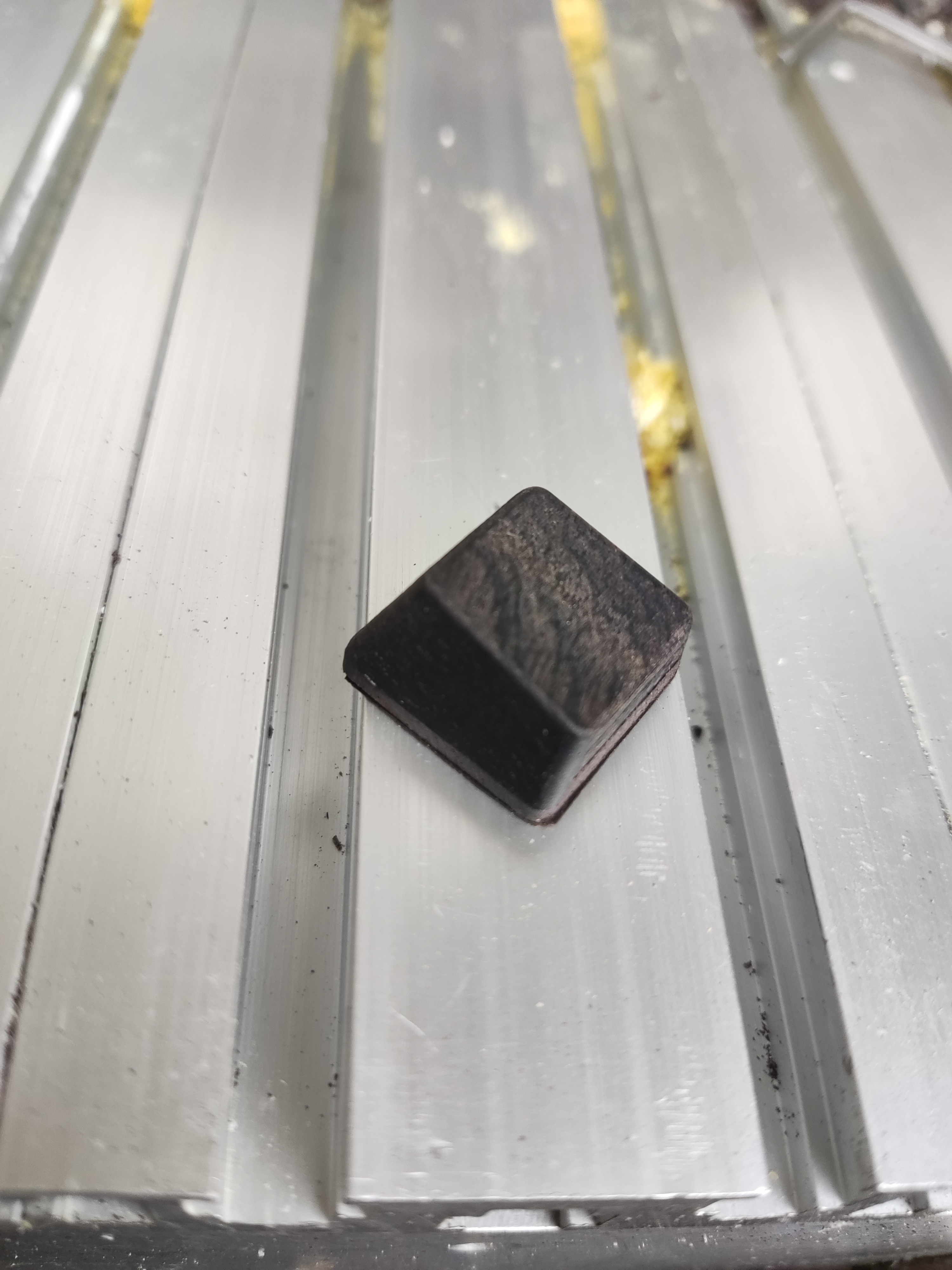
Result shots

The front side of the keycap ![]()

The back side of the keycap ![]()
-
Draw 61 Key Schematic
12/09/2023 at 13:41 • 0 commentsIn this blog post, we’re going to draw the circuit schematic of 61-key variant of Carpenter Tau keyboard. we will take into consideration that the microcontroller circuit can also be applied to the 87-key and 104-key models, ensuring that we allocate enough GPIO ports and maintain the circuit’s reusability.
Before we start
To begin with, it is essential to select a reliable EDA software that allows us to create accurate circuit schematics. My favorite option is KiCAD, which stands out for its open-source nature, impressive capabilities, and user-friendly interface. However, when it comes to finding all the necessary footprints and managing BOM assignments, it can sometimes pose a challenge.
In such cases, an alternative worth considering is EasyEDA, a free software developed by JLCPCB, a renowned PCB manufacturer and electronic components distributor. One of the notable advantages of EasyEDA is the availability of real-world electronic parts, complete with their respective prices and stock information. This invaluable feature allows us to plan and produce the projects more effectively. In this particular project, there’s no symbol library and footprint for the CH582 maincontroller but it’s right available in EasyEDA.
Now, when choosing between EasyEDA Pro and EasyEDA STD, it’s important to note that despite the “Pro” label, EasyEDA Pro remains a free software. The key difference lies in the underlying technology. EasyEDA Pro utilizes WebGL, a powerful graphics rendering technology, which ensures scalability even when dealing with complex schematics and PCB designs. On the other hand, EasyEDA STD is based on SVG, which may have limitations when handling a large number of elements. Therefore we’ll going to use EasyEDA pro for this project.
Draw the keyboard core circuit
First we draw the microcontroller part, the minuimum system, the USBC, power supply and the battery charging.
The CH582M SoC minimum system
We can find a CH582M datasheet and reference minimum system schematic from their official github:
We want the on-chip DC to DC feature to reduce battery consumption. So we can mostly copy this minimum system schematic, and let’s also have the boot key and reset key to help download and debug our program.
In order to optimize battery consumption, we aim to incorporate the on-chip DC to DC feature. By implementing this feature, we can significantly reduce power usage. To achieve this, we can leverage the minimum system schematic as reference because it by default includes the DC to DC circuit. Additionally, it would be beneficial to include dedicated boot and reset keys in the design. These keys will help the program downloading and debugging processes during our development.

Minimum System Schematic USB Type C
Now, let’s delve into the USB Type C component. As the keyboard functions as a Human Interface Device (HID), the need for USB 3.0 is unnecessary. Hence, we opt for a 12-pin (equivalent to 16-pin) Type C interface. Additionally, we leave SBU1/SBU2 unconnected. In our firmware program, it is crucial to detect when the USB Type C is connected. This is because the keyboard can be powered either by USB Type C or the battery. To address this, we establish a connection between the CC pin and one of the GPIO ports, which we label as USBCEK:

USB Type C The power and charging
Let’s list the basic requirements of power and battery charging for your keyboard. Our desired behavior is as follows:
- When the user connects the keyboard using a USB Type-C cable, it should automatically power on.
- When the keyboard is not connected via USB Type-C, the user should have the option to turn it on for wireless use or turn it off to conserve battery power.
Based on these requirements, we can draw the power and charging setup in the following way:

Power and Charging The battery charging sub circuit remains constantly connected to the USB Type C port. As a result, the charging process is always active whenever the device is connected to a power source, regardless of the switch position. The purpose of the switch is to control whether the battery functions as the power supply or not. When turning off the switch, battery is disconnected and the keyboard will power off if it’s not wired.
Also CH582M requires a stable power output of 3.3V. We utilize the ME6211 LDO, which can convert either a 5V USB power source or a 3.5-4.2V lithium-ion battery power source to the required 3.3V power.
Draw the keys, backlight and tri-mode switcher
Now that we have successfully implemented a standard system that powers up the CH582M chip and supports USB Type C connectivity, including battery charging, let’s shift our focus to the crucial aspect of the keyboard - the keys themselves.
The keys
Every individual key on the keyboard functions as a switch, effectively connecting two GPIO ports. One port signifies a specific row, while the other represents a column. When a key is pressed, the corresponding column GPIO becomes linked to the respective row, allowing our firmware program to detect this signal. Additionally, we have incorporated a switching diode for each key, which serves to prevent any potential ghosting issues.

Keys The backlight
In Carpenter Tau Keyboard it’s a wooden keyboard, which doesn’t play well with a shining RGB backlight. But we do want a plain white backlight to help pinpoint keys at night. We use a single PWM port, a MOSFET circuit to control the brightness of all keys.
The Carpenter Tau Keyboard uses a unique wooden design that doesn’t look compatible with a vibrant RGB backlight. But we do want to feature a practical plain white backlight that comes in handy during nighttime usage. To ensure optimal brightness control, the keyboard utilizes a single PWM port and a MOSFET circuit to adjust the brightness of all LED lights at once:

Backlight Tri-mode switcher
Finally we want a way to switch among wired, bluetooth and 2.4GHz connection. While a wired connection can be automatically detected through a USB Type-C cable, we also want to offer the flexibility of charging while using Bluetooth to connect to a mobile device.
Unlike some keyboards that rely on keyboard shortcuts and firmware detection these shortcuts for connection mode switching, we will opt for a distinctive approach. Because we want to minimize the symbols engraved on the wooden keycap for simplicity, as well as the constraint of limited space for indicating connection mode switch keystrokes on the keycap. Furthermore, we aim to empower users full programmability of keyboard shortcuts so don’t want certain keystrokes are occupied by switching modes. To achieve this, we will use a sliding switch to switch among connection modes: wired, 2.4GHz, and three distinct Bluetooth devices.

Tri mode switcher Final clean up and summary
Now we’ve finished all parts of the 61 key Carpenter Tau Keyboard. In next post we’ll build quite similar 87 key and 104 key circuit and the 2.4GHz dongle circuit. So we are moving the common parts of the keyboard controller to a resuable module and name it as
KeyboardCore. Only keep the 61 keys, 61 backlight LEDs and tri-mode switcher to the 61 key schematic file. The final layout looks like this:We have successfully completed the assembly of all components for the 61-key Carpenter Tau Keyboard. In our upcoming post, we will be constructing circuits for the 87-key and 104-key variants, as well as the 2.4GHz dongle circuit. Because 87-key and 104-key will be quite similar in the schematic, we move the keyboard controller part of circuit into a reusable module, named
KeyboardCore. The resulting layout is depicted below:
Keyboard Core 
Keys and Backlight You can also find the result source code of the schematic in our github: https://github.com/taukeyboard/carpenter-tau-keyboard.
-
Pickup a Suitable Microcontroller to power Carpenter Tau Keyboard
12/06/2023 at 14:25 • 0 comments
In this blog post, we’re going to research and figure out a suitable microcontroller to power Carpenter Tau Keyboard.Since we’re building a tri-mode keyboard, it would be best to have a SoC that integrates bluetooth and raw 2.4GHz RF protocol. Otherwise, we can find a generic MCU and a dedicate RF chip for handling bluetooth and 2.4GHz.
Suprisingly there isn’t many options on the market. Many famous bluetooth chips, such as ESP8266, doesn’t have low level access to raw 2.4GHz transmission. The only feasible options I found: Nordic NRF52 series, TI CC2544 / CC2640, WCH CH582 and other WCH 5xx series. After a thorough study, I decide to proceed with WCH CH582. Here is the reason:
Nordic NRF52
The main problem is the chip size. We need to build a USB dongle that is just as small as a Logitech’s Unify receiver, that means the dongle’s PCB should fit in a size of a USB Type A connector metal shell, plus 5mm plastic case. The smallest NRF52 series with USB feature is NRF52820, which is 5mmx5mm and would be quite challenge to fit in to this small dongle. In fact, the official dongle design and reference keyboard dongle (nrf Ready 2) are big ones.
Nordic do have a weaker, smaller NRF24lu1 chip that can fit into the small USB dongle, but it’s discontinued.
TI CC2544 / CC2640
TI CC2544 is a RF SoC powered by a 8051 microcontroller core, which is pretty weak, 32K flash and 2K ram. With this configuration you basically cannot run Zephyr OS and challenging to run FreeRTOS. And you have to build with official, raw APIs.
TI CC2640 is much better, ARM Cortex-M3, up to 48MHz, 128K flash and 8k ram. but let’s also check the last candidate
WCH CH582 and WCH CH5xx series
WCH CH582 is powered by a RISC-V4A architectured, 32 bit MCU, with up to 80MHz clock speed, 512K flash and 32K ram. It’s no doubt the most powerful option than TI CC2640. There are other CH5xx chips that varies on ports, flash and ram size, but otherwise quite similar. I’ll pick CH582 since it’s the mainstream on the product line, with great support and good official reference design.
A Generic MCU with RF Chips
Alternatively, many keyboards are built with a generic MCU. They are mostly starting as a wired-only keyboard, and then look for bluetooth or tri-mode upgration. They would then add a bluetooth chip or a bluetooth & 2.4GHz chip such as ESP8266, NRF24LU1 or CH2544 discussed above. This would be useful if the keyboard MCU or the 2.4GHz chip alone is not power enough to handle dual-mode or tri-mode application logic, for example, 8 bit atmega32u4. But it’s not a problem for a powerful 32 bit RISCV MCU powered SoC. It can also save the development cost, if you have already developed the wired keyboard firmware and you want to add the wireless part, it’s simply adding the wireless transmission and could be developed separately, storing the program in the separate RF chip. But we can also port open source keyboard firmwares to CH582 and add tri mode support.
For who are interested in this approach, most common microcontrollers for building keyboard is atmega32u4 and STM32. I wouldn’t recommend atmega32u4 because they’re extremely over priced. Because many famous and open source keyboard firmware, such as QMK is starting on top of atmega32u4, this chip is in high demand. And it result in, this 8 bit, quite weak MCU can be more expensive than a powerful 32 bit Cortex-M3 stm32f10c8t6. Even the STM32 option, plus another RF chip is not cost effective and STM32 core can be less powerful than 2.4GHz & bluetooth SoCs such as NRF52840 and CH582, so I think built on a powerful 2.4GHz & bluetooth SOC is the best option.
Summary
In this blog post, we looked and compared for feasible SoCs and MCUs on the market that suit for our requirement. As a result, we choose WCH CH582 for it’s powerful SoC core, direct access to raw 2.4GHz RF protocol and small packaged size.
-
Build Parametric 3d Model of Carpenter Tau Keyboard
11/26/2023 at 11:01 • 0 commentsIn this blog post, we will be constructing the complete 3D model of a keyboard. While we won’t delve into all the intricate details necessary for production, we will provide you with the final 3D model in STP format. This will give you a good overview of the keyboard’s appearance. When it comes time for production, we will revisit this topic and provide a step-by-step guide to help you accurately build a keyboard that can be manufactured.
Find the keycap metrics
To find the keycap metrics, we can explore the various keyboard models available on the internet. It’s quite convenient to obtain the metrics or the geometric details by downloading and importing a STP format model. I would choose OEM sized key and use this one as the the reference metrics.
Then we are going to import the STP format model in a parametric 3D CAD software. The reason of doing so, you can create a parametric version of the keycap that allows for adjustments such as the thickness of the border. This ensures a perfect fit for the keyboard while ensuring sufficient strength with the wooden material. Also, this can make our live easier when carving the wood. In this post, I will be using Creo Parametric as the CAD software.
Build the keycaps
Import the STP model and create a solid extrusion. Then, carefully trim the solid extusion with curved objects until they match the exact shape of the STP file.
![Single key]()
Note that each row in the keyboard has a slightly varying height, specifically referred to as R1, R2, R3, and R4. It is important to draw each of the R1-R4 as a seperate 3D model. This one provide the STP models for each row. Additionally, keys such as
Shift,Space, and others are wider in size. By utilizing parametric design, we have the flexibility to easily adjust their width according to the desired specifications. We will be constructing the standard 61, 87, and 104 key models, so it’s quite easy to find which key is which R and what it’s the width:![Reference layout]()
Build the keyboard plate
Now we need a plate to hold all the keys. Since we are building the standard layout keyboard, this can also be found online, for example, download and import this plate and import to Creo.
Build the case
The process is simpler and more relaxed compared to the keycap. You have the flexibility to adjust it according to your preferences and create an aesthetically pleasing rectangular box that can accommodate the keyboard plate therefore all the keys. It’s important to note that the case is designed to be taller at the back for added comfort, and you can take inspiration from any keyboard at hand to determine the appropriate angle.
![Case]()
Assemble
Before comming to assemble all the parts, we need a key switch to attach keycap onto the plate. We’ll use pretty standard MX type switch. We can find an open source MX switch model in OpenSCAD format. Since we don’t need to customize it, so we just download a STP version and import it to Creo. Now, we have the ability to generate an assembly file within Creo Parametric and accurately position all the keycaps on the plate. Then plate on the case. And we’re done!
![Assembled]()
Build the optional palm rest
Optionally, we can also build the option a palm rest, which is essentially a rectangular box with a curved surface designed to provide a comfortable resting place for your palm.
![Palm rest]()
Render it
Import the file into a rendering software, like KeyShot, and apply the desired wood material. Then, proceed to render it to achieve a realistic representation.
![61 key 3D Rendering]()
87 key and 104 key model
The 87 key and 104 key variants are essentially same as the 61 key one, but comes with a larger case and more keys. Also we need to create a upper case because these models don’t have keys fully covered the keyboard plate.
![87 key 3D Rendering]()
![104 key 3D Rendering]()
-
Crafting Cool: Unveil the Carpenter Tau Keyboard Project!
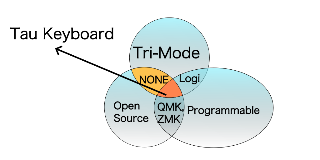
11/25/2023 at 15:58 • 0 commentsThere is a wide range of high-quality mechanical keyboards available that offer an exceptional typing experience. Personally, I have a particular fondness for keyboards made from carved wood. However, there is a drawback when it comes to the software and connectivity options that these keyboards provide. None of them offer all three features: open source capability, Tri-mode connectivity, and programmability. To address this issue, I took the initiative to create a prototype keyboard that combines the elegance of wood, Tri-mode connectivity, and plan to open source it as I continue enhance the programmable software aspect.
Why Wooden
Now, you might wonder why I specifically chose wood as the material for this keyboard. As a modern-era worker who spends hours typing each day, it’s much more enjoyable to type on a keyboard with a natural solid wood touch rather than a plastic keycap surface. Just like how you prefer writing on a solid wood desk over synthetic materials, this keyboard is designed to cater to those who share the same sentiment.
Hard wood cases and keycaps are solid and as precise as metal objects. Paint it with wood wax oil can protect it from mold, moist and decay that make it durable for many years just like your wooden house and furniture.
Additionally, wood is an environmentally friendly material. Even when it eventually worn out, it is naturally disposable and doesn’t harm the environment.
Tri-mode, Open Source Programmable: Let’s Get Fancy
Now, let’s talk about the exciting features of this keyboard: Tri-mode connectivity, open source capability, and programmability. When you purchase a high-end proprietary keyboard from renowned manufacturers like Logitech and Razer, they often come with Tri-mode connectivity, which includes wired, Bluetooth, and 2.4GHz options. However, open source keyboards on the market only offer wired and Bluetooth connectivity, lacking the 2.4GHz option. The key difference lies in latency. Bluetooth has a heavier stack, resulting in a minimum 10ms latency even for the fastest Bluetooth keyboards. Open source hobby projects can have higher latency. This difference becomes noticeable, especially for gaming purposes. With the fastest 2.4GHz keyboard, the latency can be reduced to 1ms, allowing for 1000 keystrokes per second, which is on par with a wired keyboard.
![]()
Apart from latency, other factors such as battery life and the absence of a Bluetooth receiver in some desktop computers also contribute to the preference for 2.4GHz connectivity. While major open source keyboard firmware claims doesn’t offer 2.4GHz connectivity is based on a proprietary keyboard, as a software engineer, I can assure you that implementing a fast, single-purpose protocol on top of raw 2.4GHz data transmission is not as difficult as it may seem. It’s comparable to developing an efficient messaging protocol on top of UDP or QUIC. In my prototype experiment, I was able to achieve a stable 1ms transmission latency using two low-cost 2.4GHz chips, without relying on any proprietary RF protocol. As a high-quality keyboard, I believe it’s important not to compromise in this aspect.
Now, you might wonder why you should choose an open source keyboard over a big brand one that also offers Tri-mode connectivity. Well, apart from the obvious benefits of Tri-mode connectivity, open source keyboards provide enhanced security, configurability, and programmability, thanks to the contributions of the open source community. There are already excellent high-level abstractions such as QMK, VIA, and ZMK projects available.
The name Carpenter Tau
Let’s move on to the name of this keyboard: Carpenter Tau Keyboard. During my travels, I had the opportunity to meet some incredibly skilled carpenters who demonstrated their ability to craft well-built keyboard cases, keyplates, and even precise objects as small as keycaps. This inspired me to explore the idea of using hardwood as the ideal material for creating a durable and comfortable keyboard. Combining their craftsmanship with my coding and electronics skills, I successfully built a prototype. To my surprise, it gained significant popularity among my colleagues and friends after several weeks of testing. Encouraged by their positive feedback, I decided to make these keyboards available to a wider audience, hence the name Carpenter Tau.
![Prototype Carpenter Tau Keyboard]()
As for the name “Tau”, it is derived from the sound of one of the best carpenters, Mr. Tao, in my town. I chose to associate it with the Greek letter “Tau” to symbolize the ancient history and wisdom of carpentry, while also ensuring it is easy to pronounce for English speakers.
Announce the Carpenter Tau Keyboard Project
Finally, I am excited to announce the Carpenter Tau Keyboard project. In addition to the advantages of 2.4GHz and Tri-mode connectivity, as well as open source programmability, I have separated the wooden design from the firmware/PCB design for the Tri-mode keyboard. The underlying firmware/PCB design is named Tau Keyboard and is also open sourced to meet the common needs of a Tri-mode programmable keyboard. This allows anyone in the keyboard community to build their own keyboard directly from it, make modifications, or reference its good parts. If you’re interested in learning how a professional-grade keyboard is built, I encourage you to follow this project. You’ll witness the entire process of creating the first open source Tri-mode keyboard, from start to finish!
You can stay updated on the project’s progress through the accompanying blog series. Whether you choose to build one yourself or wait for a pre-built option on Crowd Supply, I hope you’ll find the Carpenter Tau Keyboard project intriguing and worthwhile!
Carpenter Tau Keyboard
A programmable mechanical keyboard, made with black walnut and yellow rosewood