MechRedPanda
-
Construct the trial piece
11/27/2023 at 05:33 • 0 commentsWelcome back, everyone, to the fourth episode of the Difference Engine Replication Project with Mechanical Panda! In this segment, I'll share the journey of creating a prototype, aiming to validate the principles behind the difference engine using 3D printing technology.
The main objective behind crafting this prototype was twofold: to test the strength and tolerances of 3D-printed parts and to validate the rationality of the design blueprint. Think of it as a preliminary research project for the grand-scale difference engine. Although small in scale, every structural aspect and layout of this machine mirrors the full-sized difference engine.
![]()
A trial piece constructed by the London Science Museum before they constructing the full scale replica. One of the first hurdles in replicating the difference engine was sourcing the design files. You might ask, why not simply replicate Babbage's blueprints? Well, Babbage left behind a couple of "trapdoors" in his design. Firstly, his drawings lacked any annotations or explanatory notes. His intricate designs remained cryptic for over a century, further complicated by his unique symbol system designed for the machine's control sequence. Additionally, Babbage unwittingly designed a significant bug in the machine, mirroring the blunder of reversing the rotation direction of an entire set of figure wheels.
![]()
Thankfully, the Science Museum in London guided me through these pitfalls. Their comprehensive 400-page analysis deciphered Babbage's original drawings and provided a fix for this bug. Unfortunately, their restored blueprints are not publicly available, and the difference engine's original design materials were based on brass and cast iron, vastly differing from my 3D-printed plastic replication. These differences in material strength and tolerances necessitated a complete redraw of all components.
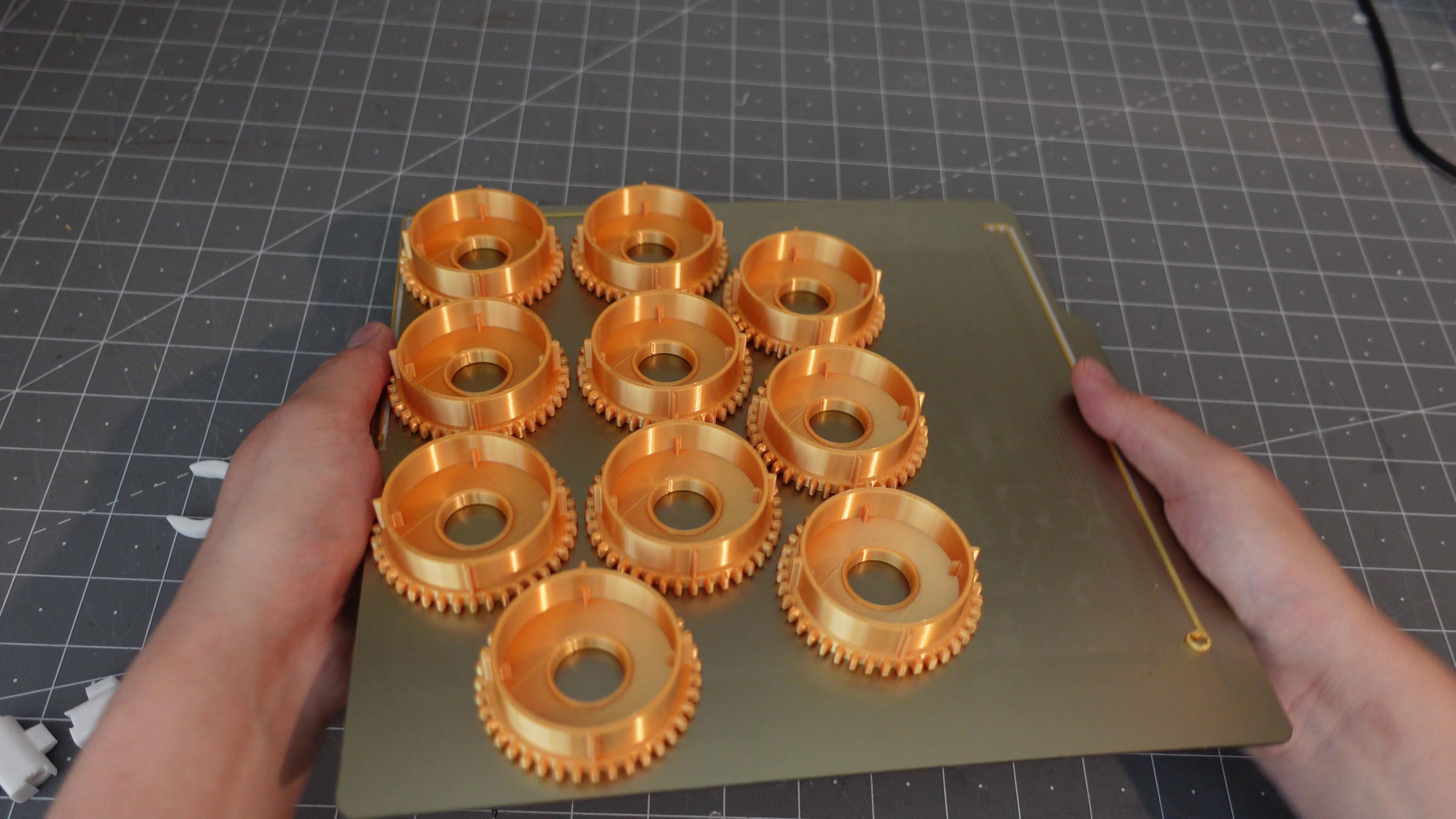
The centerpiece, the figure wheel, determined the entire machine's size. After several trials, I settled on a 60mm size for the figure wheel, allowing the maximum dimensions of the test engine to be 240mm, perfectly suiting my printer's capacity. The choice of a 20mm stainless steel tube as the driving shaft for the figure wheel prompted a recalibration of all other parts’ sizes and positions.
![]()
Despite encountering conflicts in parts' motion paths during assembly due to oversights in the blueprint, redesigning through 3D printing offered advantages. The original design required multiple independent parts and subsequent welding, introducing assembly errors, which 3D printing's integrated manufacturing process effectively mitigated. Every part of this prototype, excluding the driving shaft and nuts, was meticulously crafted using a FDM 3D printer, with a total printing duration of around three days.
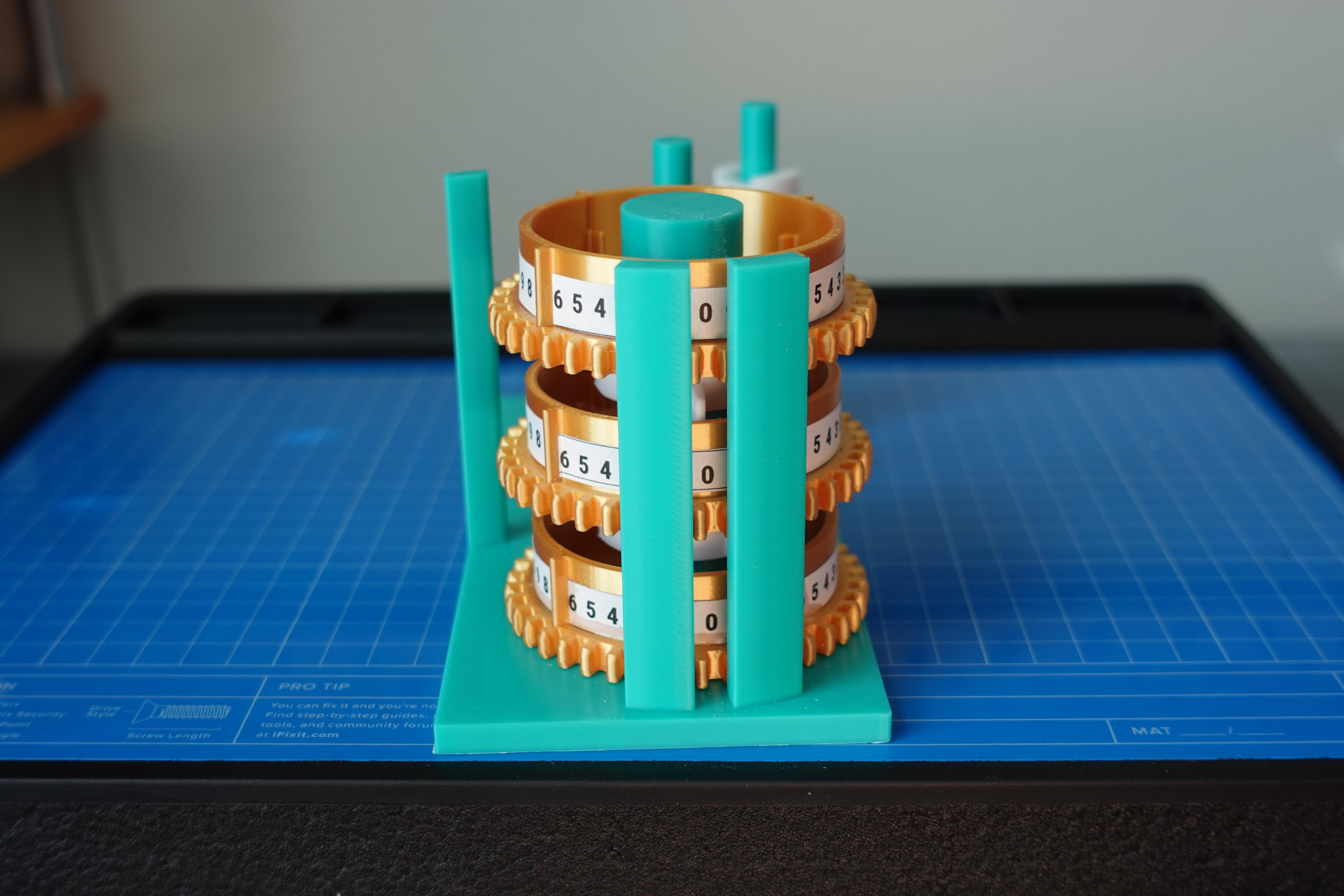
After nearly two months of dedication, I finally completed this youthful rendition of the difference engine. However, limited by its eight figure wheels, this "Youth Edition" can only store two four-digit numbers, capable of computing only linear functions. Nevertheless, this prototype's construction validates the feasibility of replicating a difference engine through 3D-printed parts, meeting the mechanical strength and precision required for its operation, albeit with alterations to the original design.
![]()
Yet, this prototype merely marks a small milestone in the replication of the difference engine. Due to its limited number of figure wheels and lack of a control system, I am already designing a more comprehensive model. If you’re intrigued by the journey of this replication project or keen on following the progress of my ongoing endeavors, don’t forget to subscribe!
Until next time, this is Mechanical Panda bidding farewell for now!
-
Carry Mechanism
11/26/2023 at 22:12 • 0 commentsIn the previous log, we delved into how the Difference Engine uses mirrored figure wheels to perform addition. You might wonder: what happens when the sum of two numbers exceeds 9? Today, we'll explore how the Difference Engine accomplishes the "carry" operation.
Imagine a Difference Engine's figure wheel capable of displaying digits from 0 to 9, vertically stacked in three figure wheels representing units, tens, and hundreds. Together, they cover a range from 000 to 999. Each figure wheel's numbers cyclically repeat after 9, resetting to 0. The "carry" refers to when a digit surpasses 9, necessitating an increase of 1 in the higher digit.
![]()
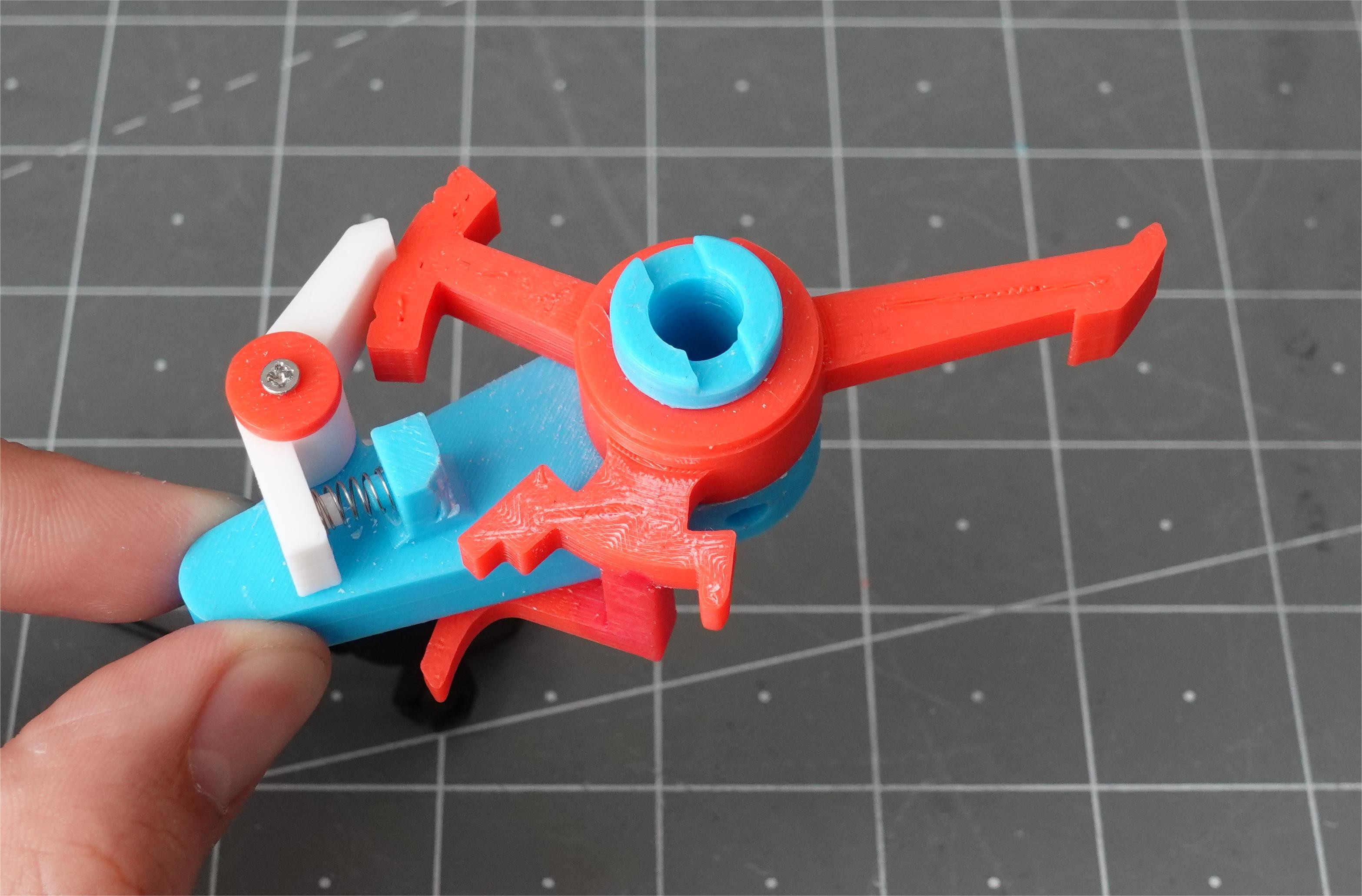
Three figure wheels stacking together, storing a three-digit number 000 The engine's carry system operates in two stages: the carry warning and the carry. The carry warning mechanism consists of a lever, base, and spring clamp with three grooves on the lever – labeled as first, second, and third positions. As values in the figure wheel surpass 9, protrusions around the figure wheel engage with the lever, initiating the carry alert phase. During this phase, the lever moves between the first and second positions, alerting the system of a potential carry.
![]()
![]()
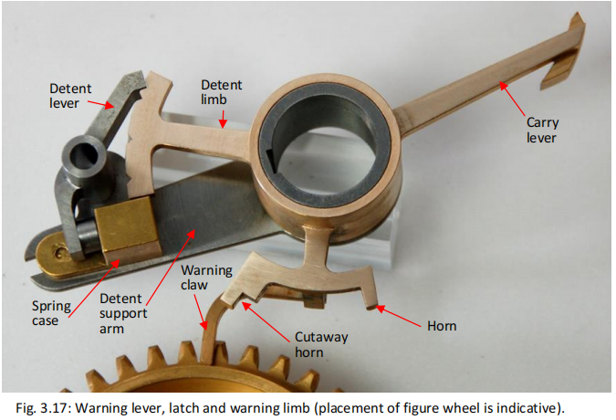
Warning lever, latch and warning limb (placement of figure wheel is indicative) reproduced by the London Science Museum. Figure taken from the DE2_TD manual Moving into the carry phase, the carry lever rotates around its axis. When the carry lever is in the first position, it remains disengaged. However, if pushed to the second position, it interacts with the higher-order lever, triggering the next phase. This connection pushes the higher-order figure wheel, incrementing its value by 1 through a ratchet mechanism.
The reason the engine doesn't directly drive the higher-order registers from the lower ones is to account for special scenarios like continuous carries. For instance, in the computation of 99 + 1, the units digit requires a carry, and as the tens place also crosses 9, a simultaneous carry must trigger in the hundreds place. This intricate design facilitates continuous carries by setting the carry levers at a specific angle, allowing each digit to trigger the next without overwhelming the system's load. Unlike a direct driving mechanism, this design scalability allows for an expandable carry system, adaptable to different register configurations without overburdening the material's strength.
This extendable design philosophy permeates the Difference Engine, reflecting Charles Babbage's aspiration to create a universal calculating machine. If you want to explore more about the Difference Engine's design or follow the progress of my replicated version, don't forget to subscribe. This is Mechanical Panda, signing off until our next log!
-
Figure Wheels
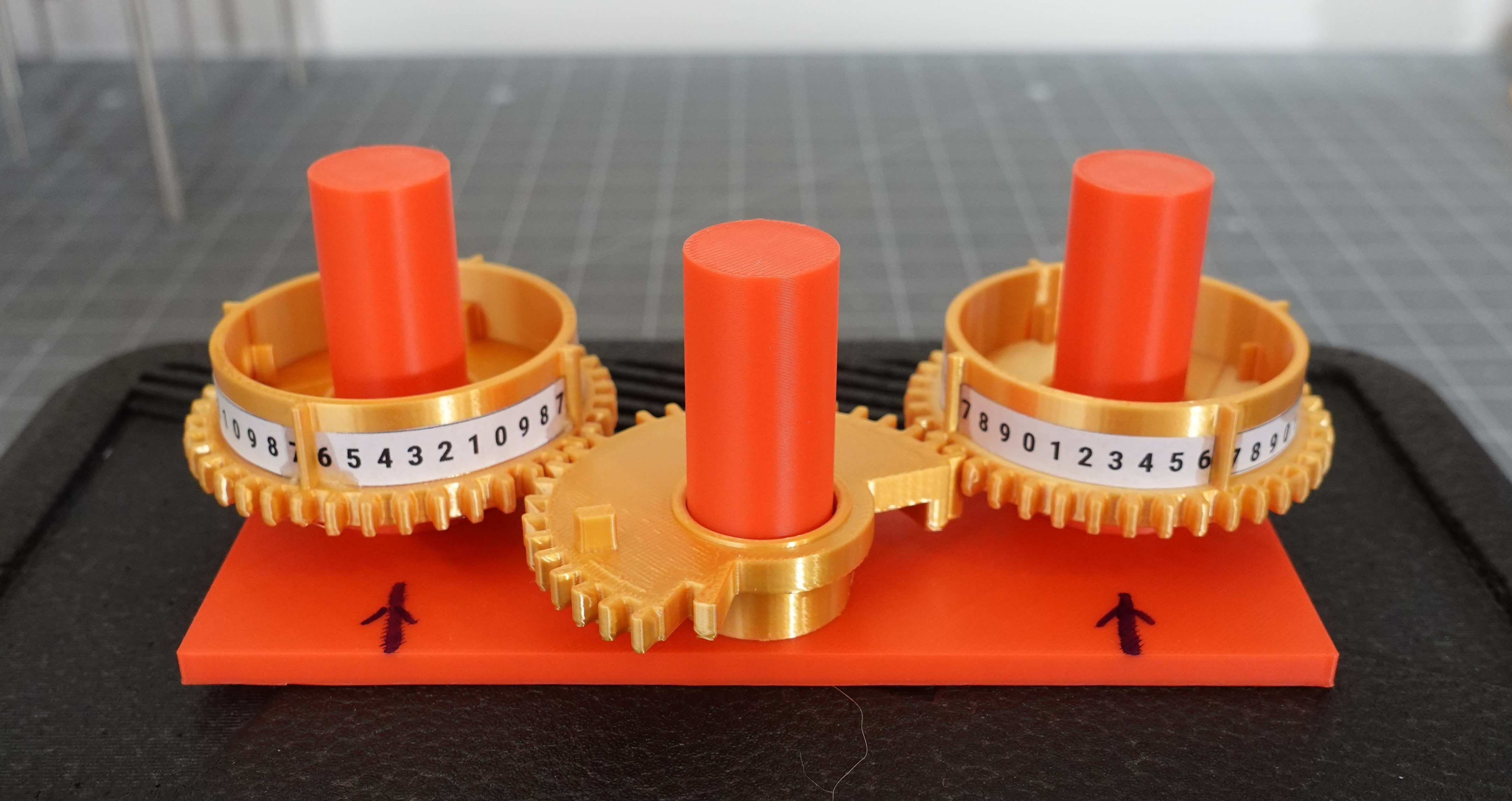
11/26/2023 at 05:57 • 0 comments![]()
Figure Wheels and Sector wheels
The figure wheels are made from 40-teeth gear. Each figure wheel can store one digit (0 to 9).
The nerigboring figure wheels are connected by a sector wheel, which is a section of a 40-teeth gear.
The combination of figure wheels and sector wheel can perform additions.
I chose the size of figure wheel to be 60mm, so that it is not too small and hard to print, and not too large to fit in my 3D printer.
![]()
3D printed figure wheels 
Figure wheel numbers -
The Difference Engine No.2
11/26/2023 at 05:51 • 0 commentsThe story of the Difference Engine No. 2 finds its roots in the pioneering work of a young mathematician named Charles Babbage. In the early 19th century, Babbage presented a short paper titled "A note respecting the application of machinery to the calculation of astronomical tables" at the Royal Astronomical Society, marking the beginning of a groundbreaking endeavor.

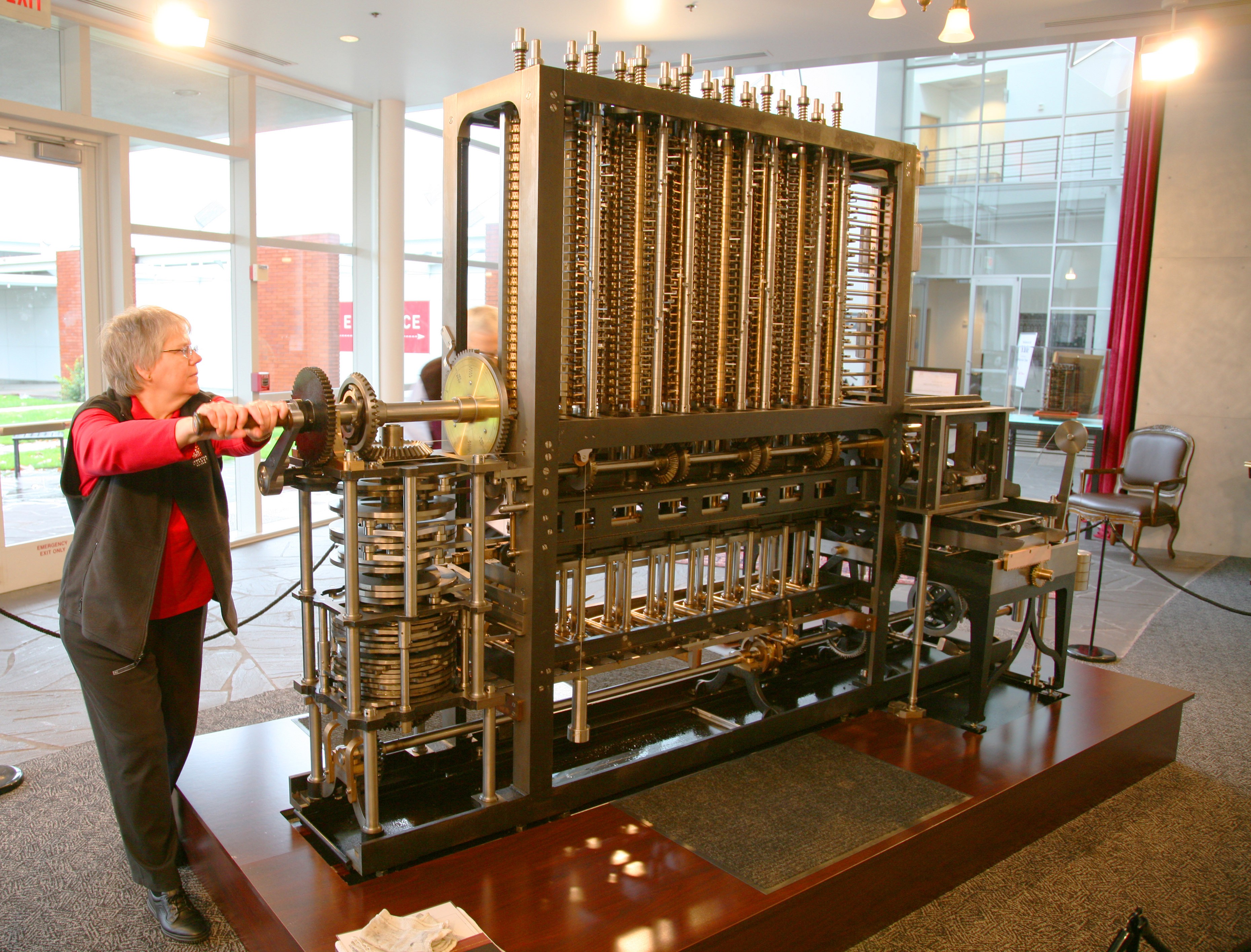
A replica of the Difference Engine No.2 built by the London Science Museum based on Charles Babbage's drawings. Credit: London Science Museum Living in an era when the first industrial revolution had mostly unfolded, complex mathematical calculations had become integral in fields such as finance, navigation, and military applications. The need for accurate computations was crucial - from determining the latitude and longitude of ships on long voyages to calculating firing tables for artillery and aiding astronomers in their daily astronomical computations.
During this time, mathematical tables served as indispensable tools, offering precomputed values for various functions, simplifying arithmetic and reducing the margin of error in calculations. However, creating these tables was a laborious process that relied on human computers—individuals who manually executed computations based on algorithms designed by mathematicians. This method was not only resource-intensive but also prone to errors, potentially leading to significant consequences such as ships getting lost at sea.
Charles Babbage was intrigued by this problem and envisioned a solution that would eliminate human errors from mathematical computations. His idea, unlike others at the time, aimed to reduce errors by reducing human involvement. In 1821, Babbage expressed his desire to his friend John Herschel, stating, "If we could only get the machine to do the calculations!"
In his 1822 paper, Babbage proposed the construction of a mechanical device that could automatically compute complex mathematical functions using gears, levers, and rotating cylinders. This machine aimed to expedite and lower the cost of creating mathematical tables, ultimately rendering other mathematicians and human computers obsolete - a concept that aligned with the reduction of human error and increased efficiency.
Named the "Difference Engine," referencing the method of finite differences, Babbage's machine embarked on a challenging journey. From 1822 to 1833, with funding from the British government, Babbage and his engineering partner completed a fraction of the Engine, comprising approximately 1/7th of the computational components, which alone consisted of around 2,000 parts. Yet, due to difficulties in machining parts and conflicts among partners, the project faced constant delays and budget overruns.

Demonstration model of Babbage’s Difference Engine No.1, Credit: London Science Museum Ultimately, in 1833, the British government terminated funding, having already invested a substantial sum, around £17,500 - a significant amount considering it could have purchased 22 brand-new steam locomotives in that era.
However, Babbage was undeterred by the failure of the Difference Engine project. He began envisioning an even more advanced machine - the Analytical Engine - a universal mechanical computer that could compute any mathematical function. Although never fully realized, the principles of the Analytical Engine influenced Babbage's reworking of the Difference Engine.
Between 1847 and 1849, Babbage redesigned the Difference Engine, creating the Difference Engine No. 2. This newer design significantly simplified the structure, requiring around 8,000 parts, roughly a quarter of his initial estimate for the complete Engine. Despite his efforts to seek funding from the British government again, he faced rejection from the Prime Minister.
Charles Babbage passed away in 1871, leaving behind numerous designs for both the Difference Engine and the Analytical Engine. These designs, known as the Babbage Papers, were donated by his heirs to the Science Museum in London, where they remained stored away for a century.
Though Babbage never saw his Difference Engine fully realized, its legacy endured. It embodied precision akin to a clock, the robustness of a steam engine, and the foresight of the digital age. This coexistence of antiquity and advancement exuded a unique aesthetic - often associated with the genre of steampunk.
The London Science Museum holds a special place in preserving Charles Babbage's legacy through its meticulous recreation of the Difference Engine No. 2. This replica stands as a testament to Babbage's visionary designs and engineering principles.
The museum embarked on a remarkable endeavor to bring Babbage's vision to life. Utilizing the detailed designs and plans left behind in the Babbage Papers, a team of skilled engineers and craftsmen meticulously recreated the Difference Engine No. 2.
The process of replicating such a complex mechanical device was an extraordinary feat. With a keen eye for historical accuracy and precision engineering, the team meticulously crafted each component of the Engine, staying true to Babbage's original specifications.
The replica at the London Science Museum showcases the intricate gears, levers, and mechanisms that constitute this marvel of 19th-century engineering. Visitors can witness firsthand the complexity and ingenuity behind Babbage's vision, gaining insight into how this mechanical computer was intended to function.
The Difference Engine No. 2 replica serves not only as an exhibit but also as an educational tool, allowing people to appreciate the evolution of computing and the profound impact of Babbage's ideas on modern technology. It provides a tangible link to the past, offering a glimpse into the innovative spirit of early computing pioneers and their contributions to shaping the digital world we live in today.
The meticulous craftsmanship and dedication poured into replicating this historic machine at the London Science Museum stand as a tribute to Charles Babbage's legacy, ensuring that his groundbreaking work continues to inspire and educate future generations about the roots of computing and technological innovation.
![]()
3D Print Babbage's Difference Engine No.2
A fully functional replica of Charles Babbage's Difference Engine No.2 with 3D printed parts