 Mukesh Sankhla
-
1Introduction
![]()
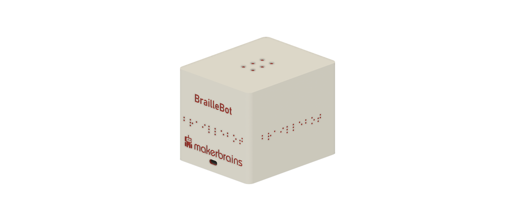
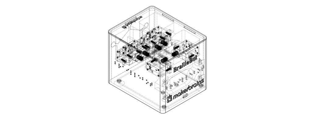
Welcome to the wonderful world of BrailleBot, your very own Braille language trainer! BrailleBot is a special project designed to make learning the Braille alphabet not only easy but also super fun, especially for kids who are visually impaired.
Imagine having a personal Braille tutor right at your fingertips! What makes BrailleBot even more amazing is that it won't break the bank—it's a budget-friendly option, coming in at just under $100. Now, let's dive into what BrailleBot is all about.
BrailleBot is a hands-on learning tool crafted to teach the Braille alphabet from A to Z. It's like having a playful friend that guides you through the world of Braille in an engaging way. The surface of BrailleBot is equipped with six dots, and each dot is controlled by a small servo motor. These dots create the tactile sensations that represent different letters in the Braille alphabet.
But wait, there's more! BrailleBot doesn't just stop at tactile learning—it also has an audio system. This means you not only feel the Braille dots but also hear the corresponding letters being vocalized. It's a multi-sensory experience, making the learning journey more enjoyable and effective.
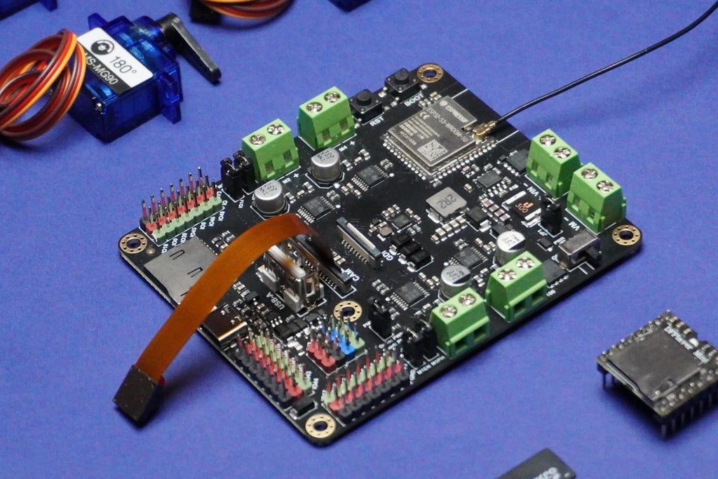
Behind the scenes, BrailleBot is powered by the Romeo ESP32-S3 board, the brains that ensure everything runs smoothly and efficiently. So, whether you're a beginner trying to grasp the basics of Braille or a parent looking for an accessible and affordable learning tool for your visually impaired child, BrailleBot is here to open up a world of possibilities.
Get ready to embark on a Braille adventure with BrailleBot—where learning is hands-on, interactive, and loads of fun!
-
2Supplies
![]()
![]()
![]()
![]()
![]()
![]()
![]()
![]()
![]()
![]()
![]()
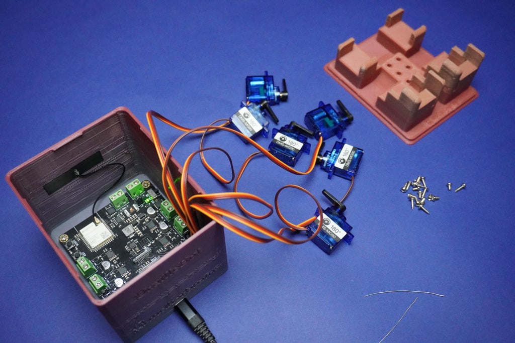
1x Romeo ESP32-S3 Development Board
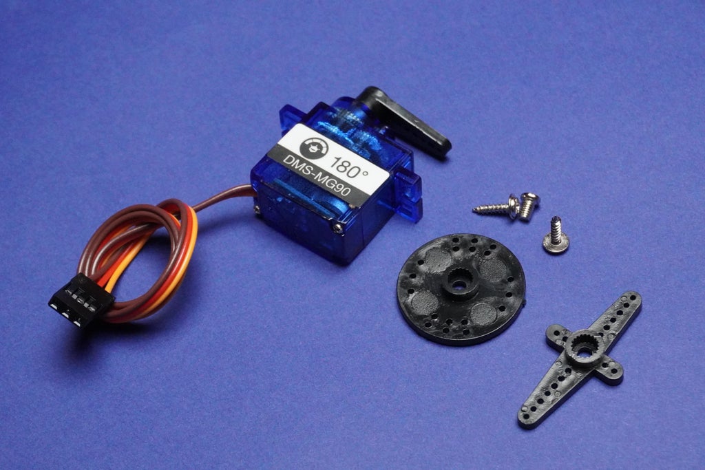
6x Servo Motors
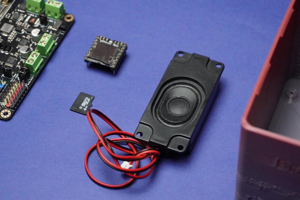
1x Memory Card
1x Speaker
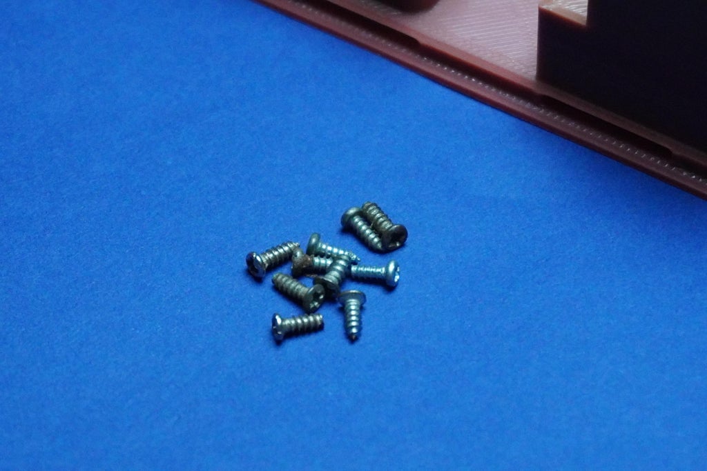
1x Screws
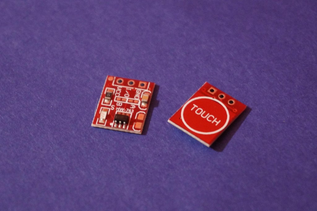
2x Touch Sensor
My Equipment's:
Sponsored By NextPCB
This project is successfully completed because of the help and support from NextPCB -Reliable Multilayer PCB Manufacturer. NextPCB is one of the most experienced PCB manufacturers in Global, has specialized in the PCB and assembly industry for over 15 years.
Order high-quality, reliable PCB starting at $1.9, multilayer starting at $6.9:
https://www.nextpcb.com/pcb-quote
Enjoy free PCB assembly for 5 boards:
https://www.nextpcb.com/pcb-assembly-quote
DFM free online PCB Gerber viewer:
-
3How BrailleBot Works?
1. Servo Motor Control:
- Each of the 6 dots on the Braille surface is linked to a servo motor.
- When a specific alphabet is chosen for display, the corresponding servo motors rotate by a set degree, causing the connected dot to lift.
2. Dot Movement:
- The servo motors are programmed to lift the dots precisely, creating a tactile representation of Braille characters.
- This controlled movement ensures accurate positioning of the dots on the Braille surface, providing a clear and distinguishable touch experience.
3. Alphabet Selection:
- The control system of BrailleBot, powered by the Romeo ESP32-S3 board, determines which servo motors to activate based on the selected alphabet.
- For instance, to display the letter 'A,' specific servo motors corresponding to the dots forming the letter 'A' are rotated.
4. Audio System Integration:
- Simultaneously, the audio system connected to BrailleBot announces the selected alphabet.
- This audio feedback serves to reinforce the tactile learning experience, creating a multi-sensory approach to Braille education.
- The synchronization of tactile and auditory input enhances the user's understanding of the Braille characters and their pronunciation.
5. User Interaction:
- BrailleBot incorporates two touch sensors, one on each side, allowing users to interact with the system.
- Users can navigate through the Braille alphabet using these touch sensors. One sensor may be designated for moving to the next alphabet, while the other is for moving to the previous one.
![]() This interactive feature promotes user engagement, making the learning process more dynamic and enjoyable.
This interactive feature promotes user engagement, making the learning process more dynamic and enjoyable.
![]()
![]()
![]()
![]()
https://content.instructables.com/FGD/C9NF/LPGX6440/FGDC9NFLPGX6440.mp4
-
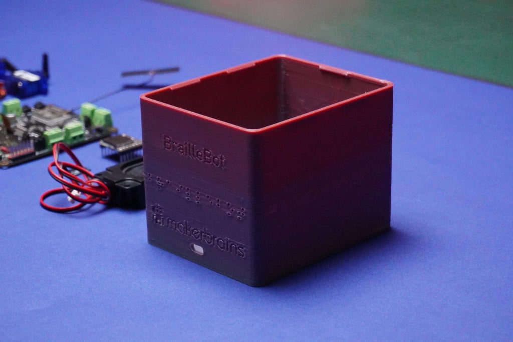
43D Printing
![]()
![]()
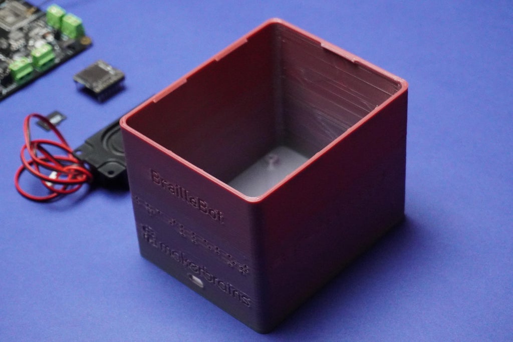
To bring your BrailleBot to life, let's start by 3D printing the essential components. Follow these steps to create the physical structure of your BrailleBot:
You can view BrailleBot design directly on your browser, download it, open it in Fusion 360 software and modify it according to your requirements.
Download all the provided 3D files (stl) and 3D print them.
I am using 2mm layer height and 100ms as speed On My Kobra Neo 2.
Parts:
1x Top.stl
1X Main.stl
4x Dot1.stl
2x Dot2.stl
-
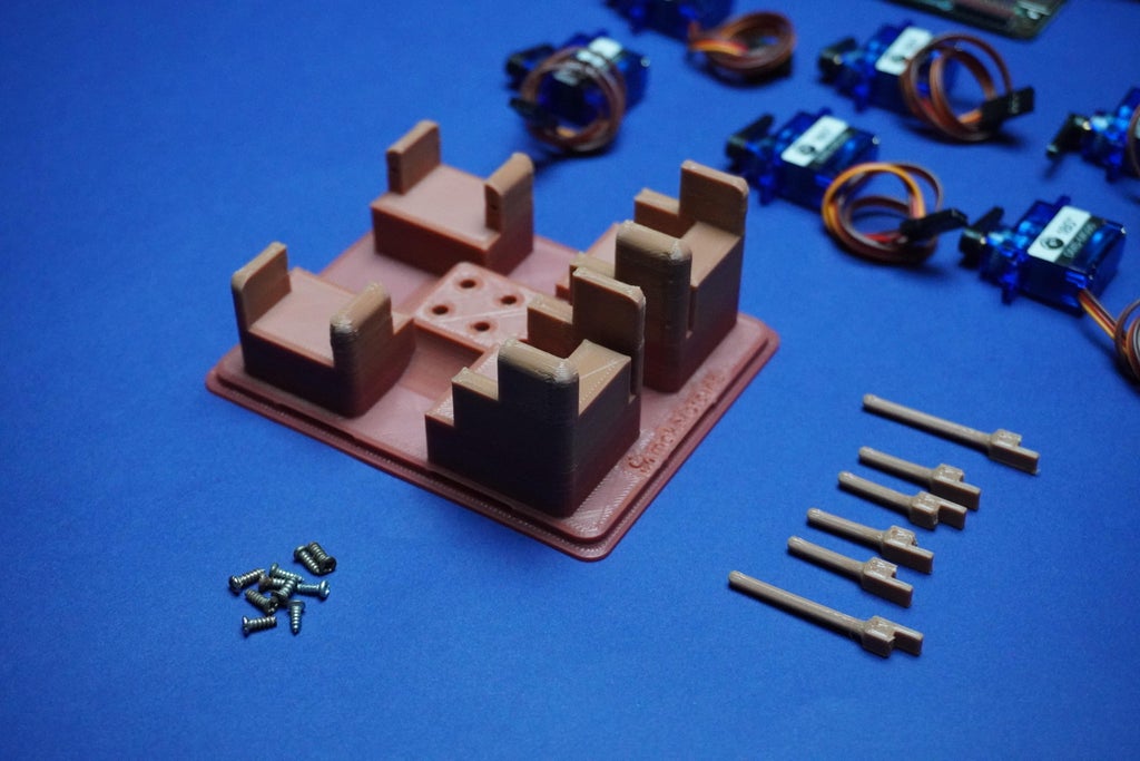
5Small Adjustment
![]()
![]()
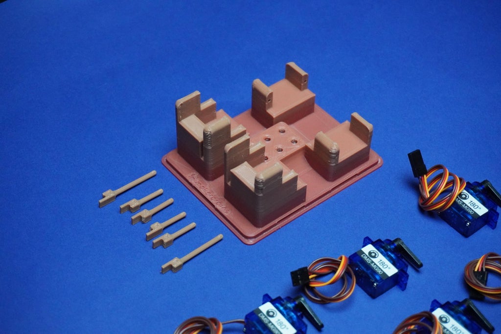
Minor adjustment needed in the Dots 3D design:
- Initially, I overlooked including holes to connect the dot pieces to servo motors. I have now revised the 3D model for you.
- However, be aware that these holes are quite small, and there's a possibility that the 3D printer might not capture them accurately.
- In such a case, you can use a small tool to manually create these holes on each dot piece.
-
6Assembly 1
![]()
![]()
![]()
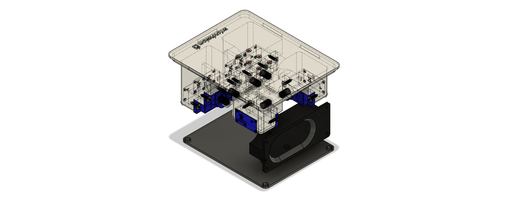
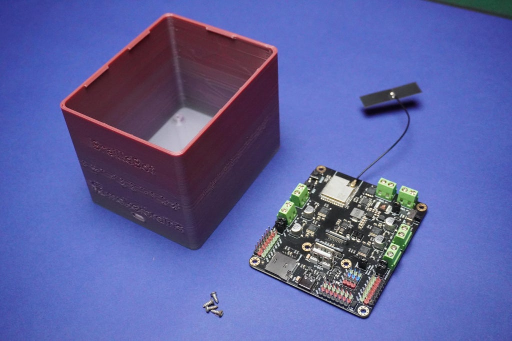
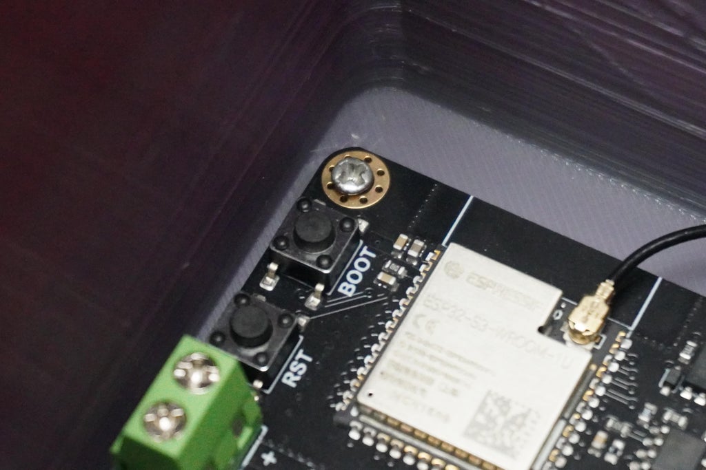
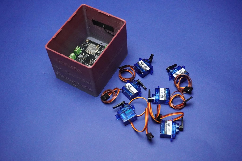
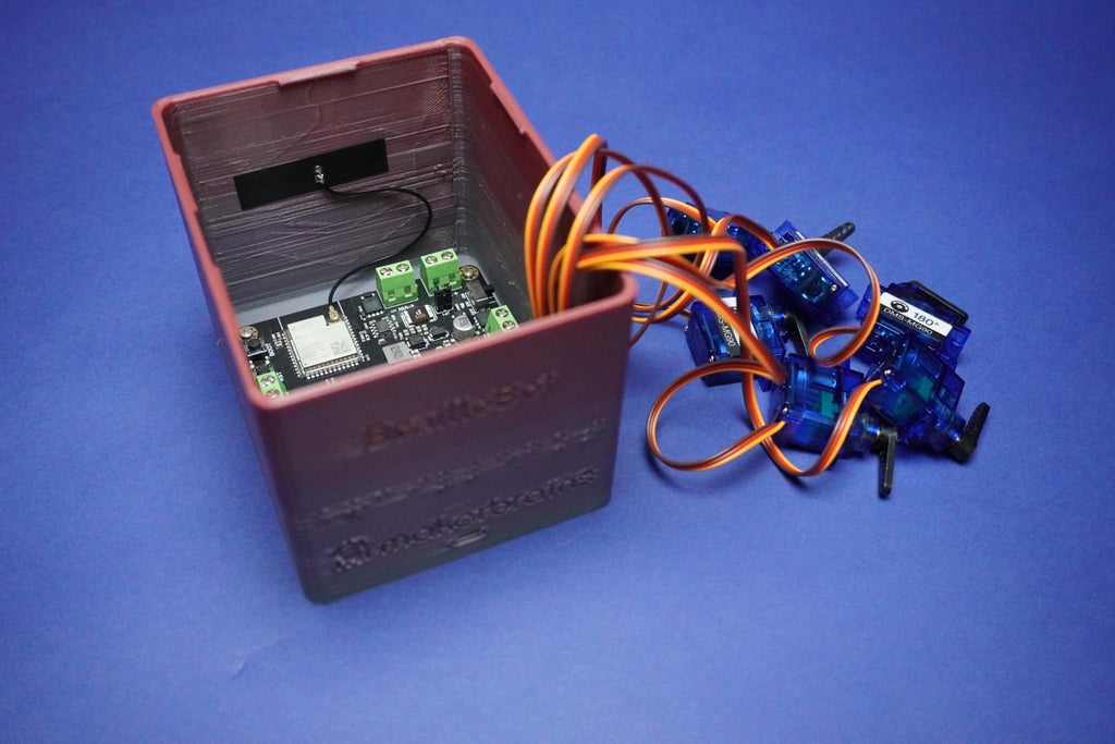
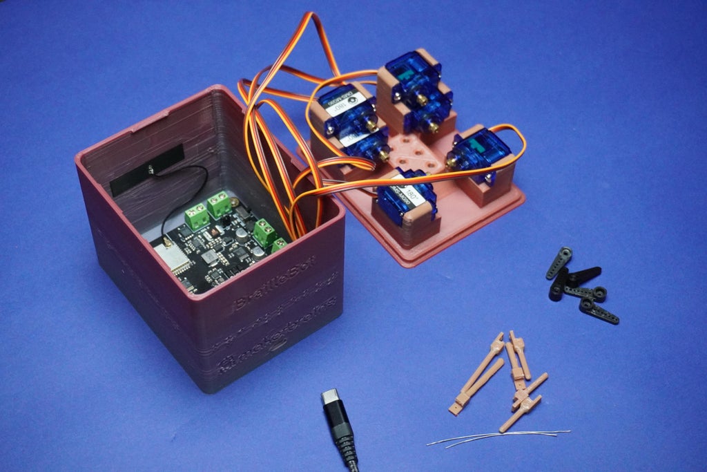
- Proceed by attaching the Romeo ESP32 board to the main 3D printed enclosure using 2mm screws.
- Align the Type C opening with the screw holes and carefully secure them in place.
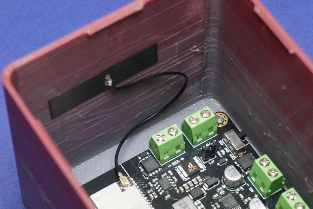
- Additionally, remove the antenna sticker and affix the ESP32 antenna onto the enclosure wall.
- Exercise caution during the screwing process to avoid potential damage to the electronics.
-
7Connecting Servo Motors
Connect the 6 servo motors by attaching their servo connectors to the following pins:
- 1st motor: IO4
- 2nd motor: IO5
- 3rd motor: IO6
- 4th motor: IO7
- 5th motor: IO15
- 6th motor: IO16
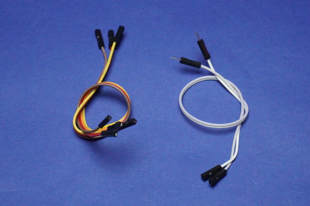
Ensure that the brown terminal of the connector is connected to the GND line, the red terminal is connected to 3V3, and the orange terminal is connected to the respective IO line, as illustrated in the provided image.
![]()
![]()
-
8Motor Initialization
![]()
![]()
![]()
![]()
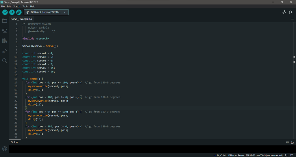
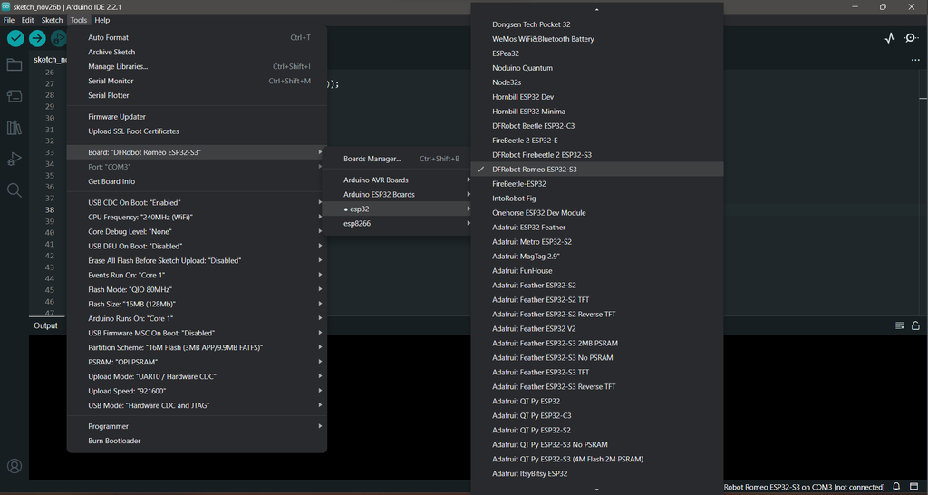
To initialize the motors position, follow these steps:
- Ensure that you have the Arduino IDE installed with the latest ESP32 board manager.
- If you haven't installed the ESP32 board manager, you can follow the instructions in this link: Installing the ESP32 Board in Arduino IDE.
- Once the ESP32 board manager is installed, connect the Romeo ESP32-S3 to your PC using a Type-C cable.
- Copy and paste the provided code below.
/* makerbrains.com Mukesh Sankhla @mukesh.diy */ #include <servo.h> Servo myservo = Servo(); const int servo1 = 4; const int servo2 = 5; const int servo3 = 6; const int servo4 = 7; const int servo5 = 15; const int servo6 = 16; void setup() { for (int pos = 180; pos >= 0; pos--) { // go from 180-0 degrees myservo.write(servo1, pos); delay(15); } for (int pos = 0; pos <= 180; pos++) { // go from 180-0 degrees myservo.write(servo1, pos); delay(15); } for (int pos = 0; pos <= 180; pos++) { // go from 180-0 degrees myservo.write(servo2, pos); delay(15); } for (int pos = 180; pos >= 0; pos--) { // go from 180-0 degrees myservo.write(servo2, pos); delay(15); } for (int pos = 180; pos >= 0; pos--) { // go from 180-0 degrees myservo.write(servo3, pos); delay(15); } for (int pos = 0; pos <= 180; pos++) { // go from 180-0 degrees myservo.write(servo3, pos); delay(15); } for (int pos = 0; pos <= 180; pos++) { // go from 180-0 degrees myservo.write(servo4, pos); delay(15); } for (int pos = 180; pos >= 0; pos--) { // go from 180-0 degrees myservo.write(servo4, pos); delay(15); } for (int pos = 180; pos >= 0; pos--) { // go from 180-0 degrees myservo.write(servo5, pos); delay(15); } for (int pos = 0; pos <= 180; pos++) { // go from 180-0 degrees myservo.write(servo5, pos); delay(15); } for (int pos = 0; pos <= 180; pos++) { // go from 180-0 degrees myservo.write(servo6, pos); delay(15); } for (int pos = 180; pos >= 0; pos--) { // go from 180-0 degrees myservo.write(servo6, pos); delay(15); } } void loop() { }</servo.h>- Select the Board type as "DFRobot Romeo ESP32-S3" in the Arduino IDE.
- Choose the correct port for your connected Romeo ESP32-S3.
- Upload the code to the board.
This code set the servos to the corresponding initial positions.
-
9Servo Motors Assembly
![]()
![]()
![]()
![]()
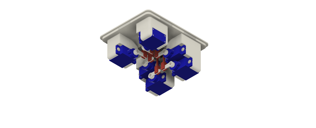
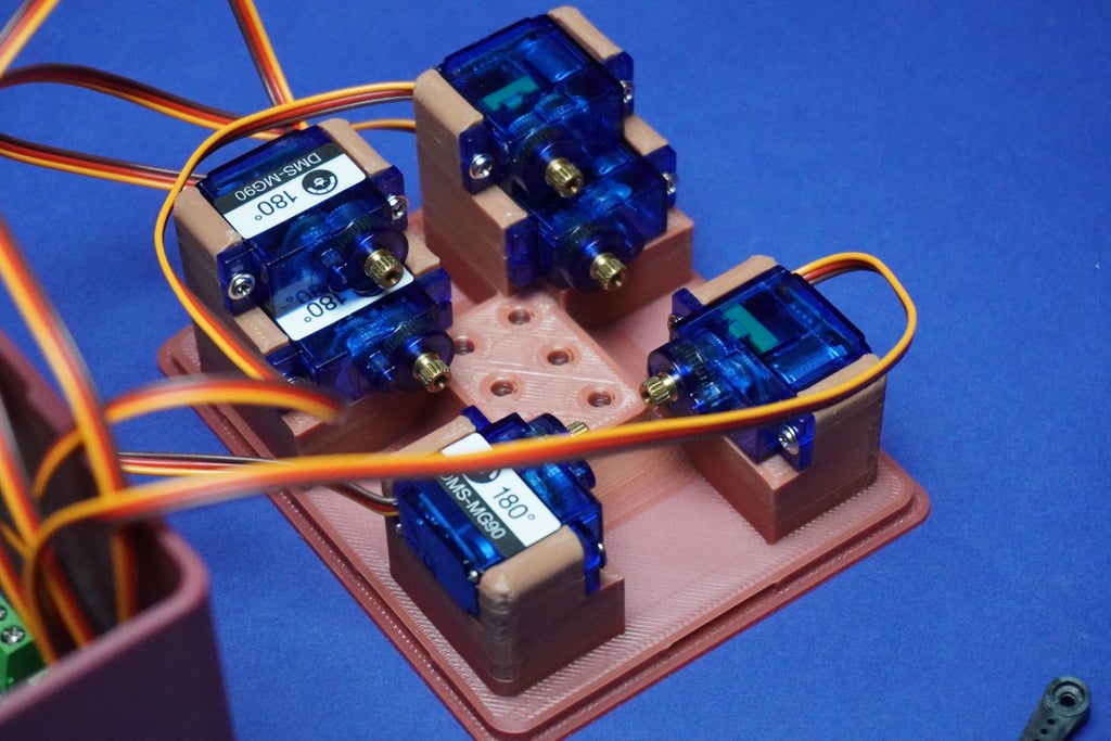
After completing the previous step, follow these instructions to assemble the servo motors into the Top 3D printed part:
- Begin by removing all the arms from the servo motors.
- Screw each servo motor into its corresponding position on the Top 3D printed part:
- Use the screws provided with the servo kit to secure each motor in place.
- Ensure the arrangement is as follows:
1, 2
3, 4
5, 6
-
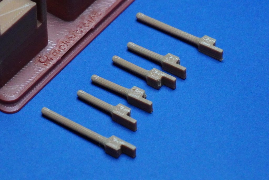
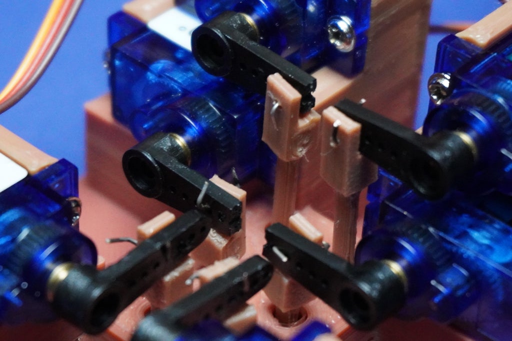
10Dots Assembly
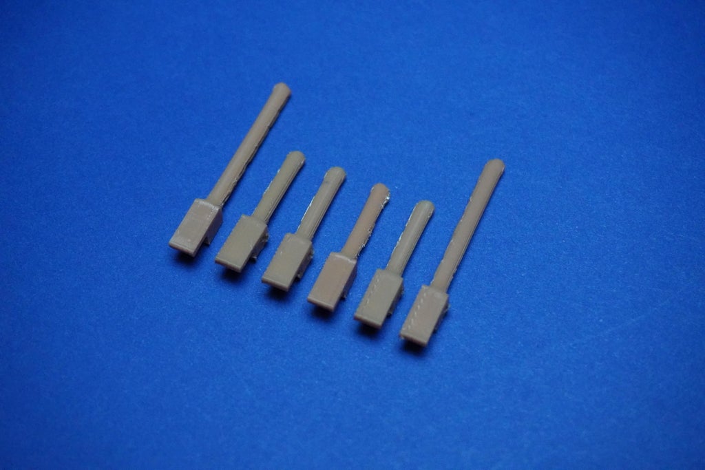
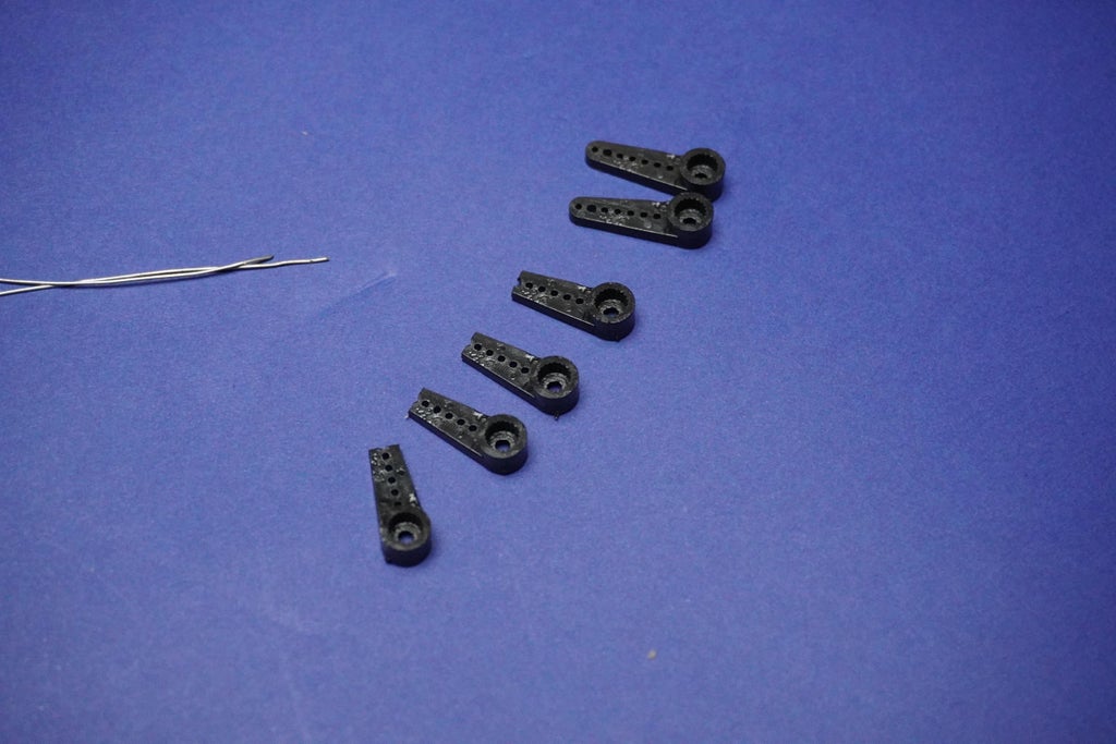
- First we have to cut 4 arm tips to adjust the arm length and avoid overlap.
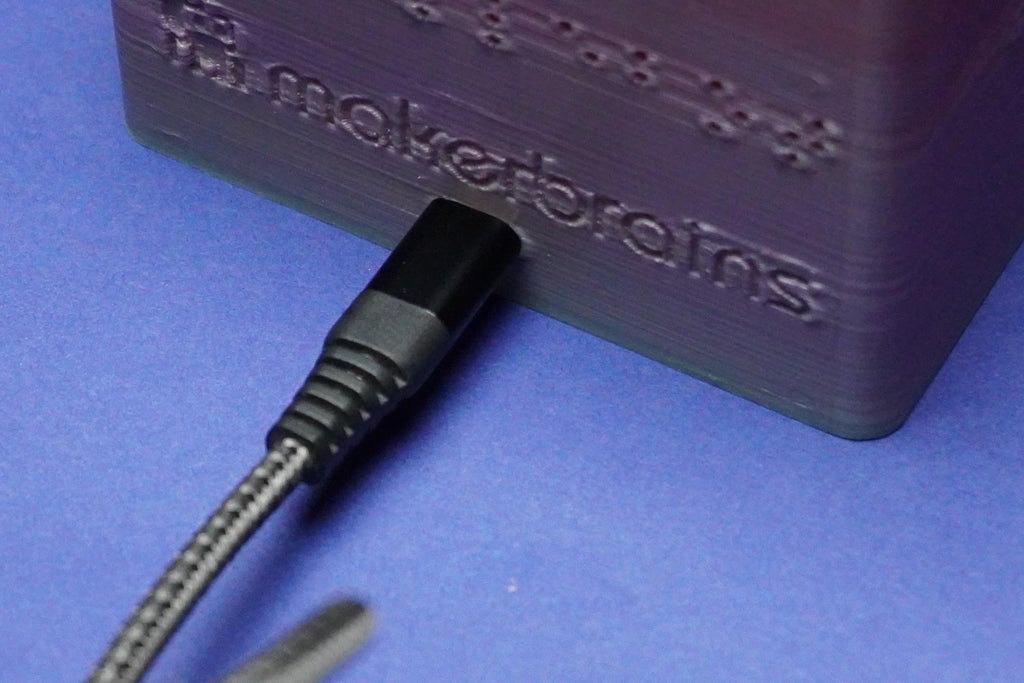
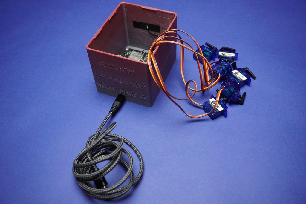
- Plug the CType connector into your PC or any 5V power source, such as a power bank or a 5V adapter so that motors can initialize.
- Ensure that all arms are removed from the motors, as mentioned in the previous step, to prevent damage during initialization.
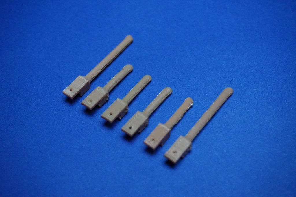
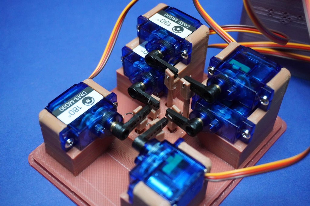
- With the system powered, carefully place all dot shafts according to their specified lengths.
- Connect each dot shaft to its corresponding arm and servo motor, using the single-strand wire as illustrated in the provided image.
- Be cautious during this step as the holes for assembly are tiny and may require precision.
- Take your time to ensure each dot shaft is securely connected to its designated arm and servo motor.
![]()
![]()
![]()
![]()


 This interactive feature promotes user engagement, making the learning process more dynamic and enjoyable.
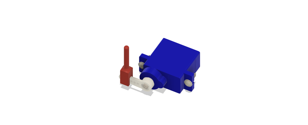

Discussions
Become a Hackaday.io Member
Create an account to leave a comment. Already have an account? Log In.