The tests so far have proven that the theory can be realised and so it is time to make the circuit more permanent. First task, move the circuit from breadboard to proto/perf board.
The layout is nothing too complex and can be constructed out on a moderate sized piece board. The task is to translate the schematic:
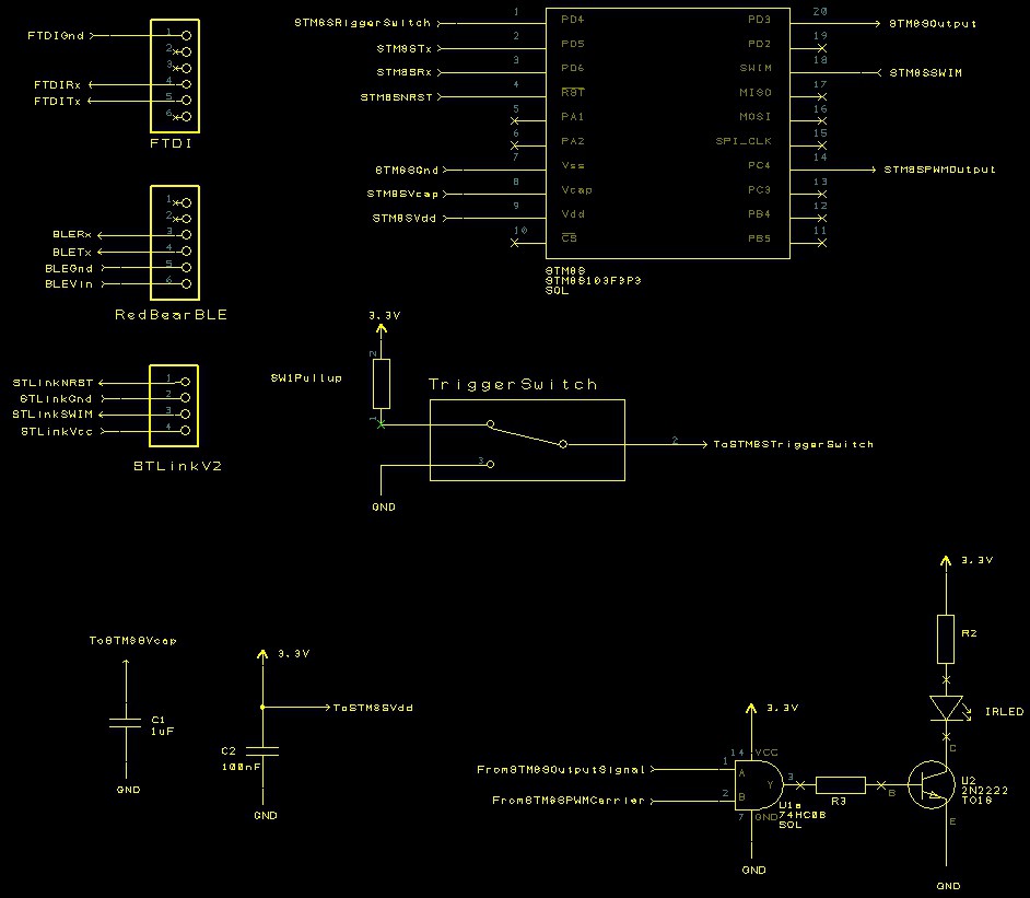 into a working board.
There are plenty of resources on the web to aid in the translation of the circuit into a working prototype so I won't cover this topic here. After a few hours with the soldering iron and the components bin I ended up with the following:
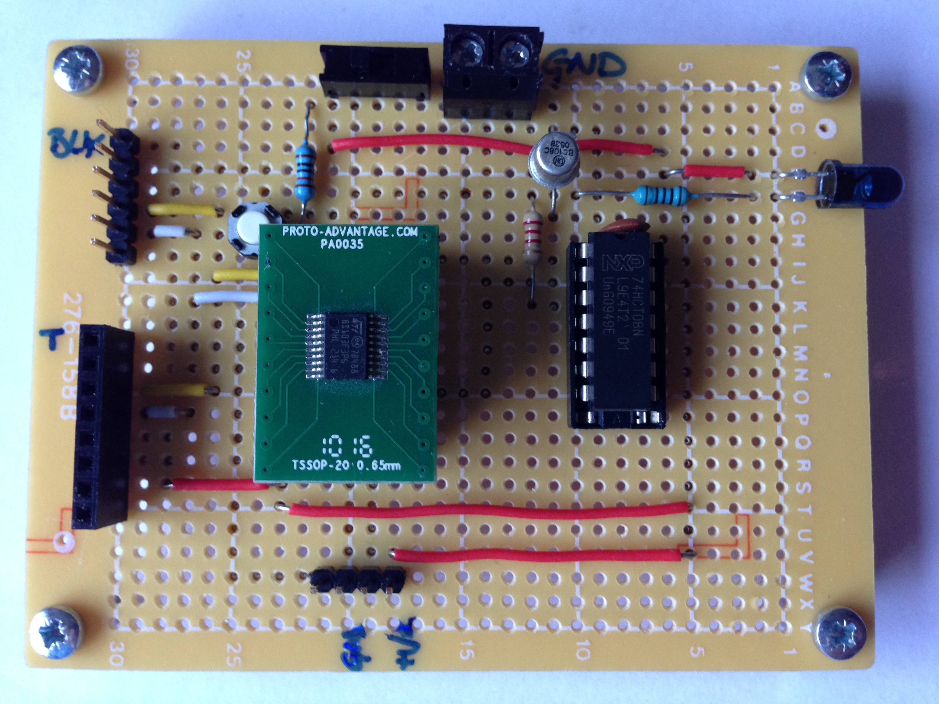 The two connectors to the left of the board are the TTL serial (top male) and RedBear BLE (bottom female) connectors. The connector on the lower part of the board allows the connection of the STLink/V2 programmer to the STM8S.
A quick test shows that the software still works. I now have a more permanent prototype to work with.
Manufacturing a PCB
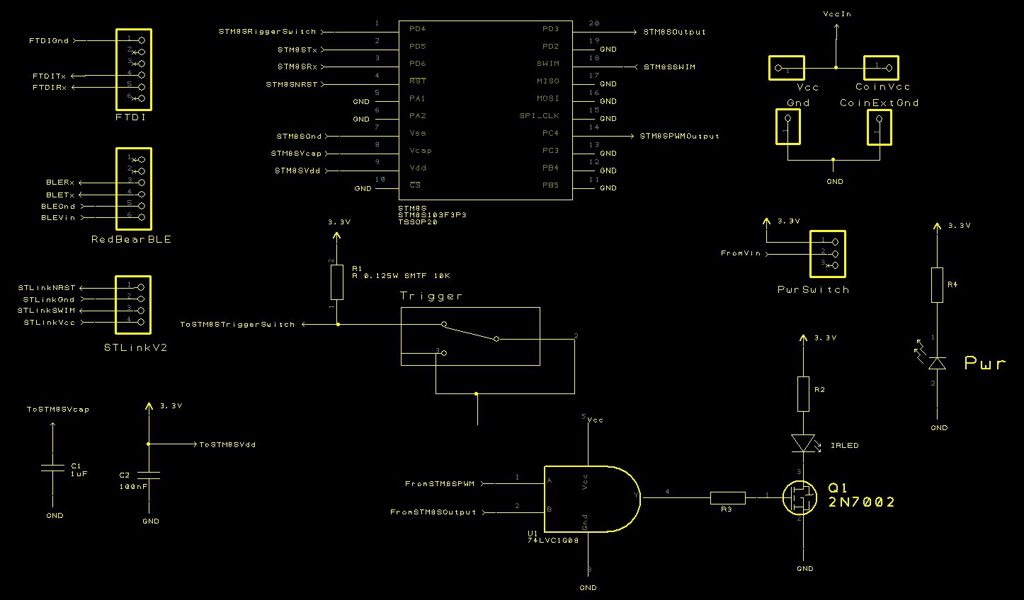
Whilst the board above is OK for prototyping the circuit is intended to end up on a manufactured PCB. A quick look at the schematic and we find we should add some additional parts:
- Connection points for power (options for bench supply, coin cell and 2 x AA battery)
- Power LED to indicate if the board is powered
- Single AND gate to replace the four AND gate package used above
- Ground any unused pins
Making these modifications results in the following schematic:
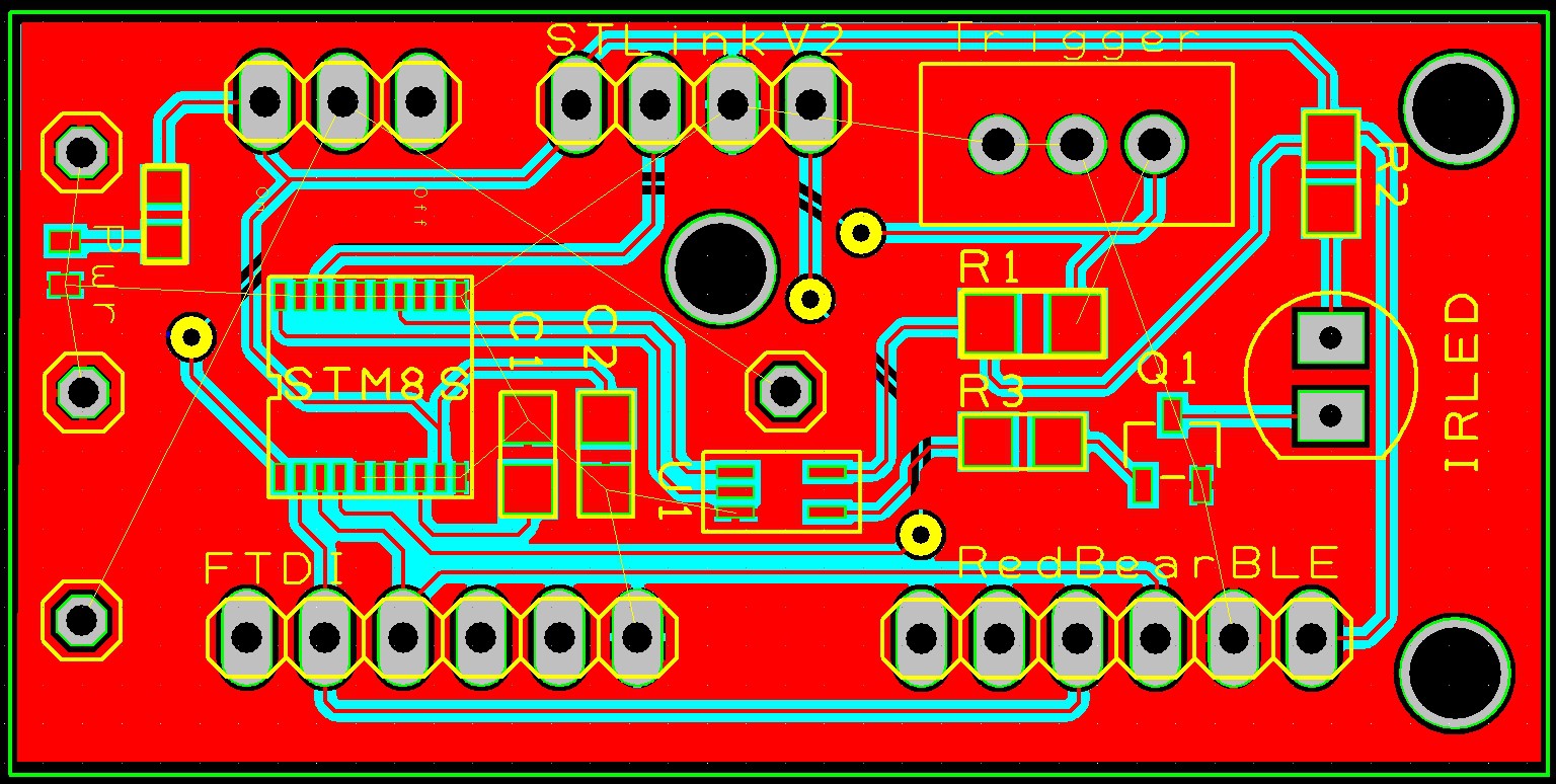
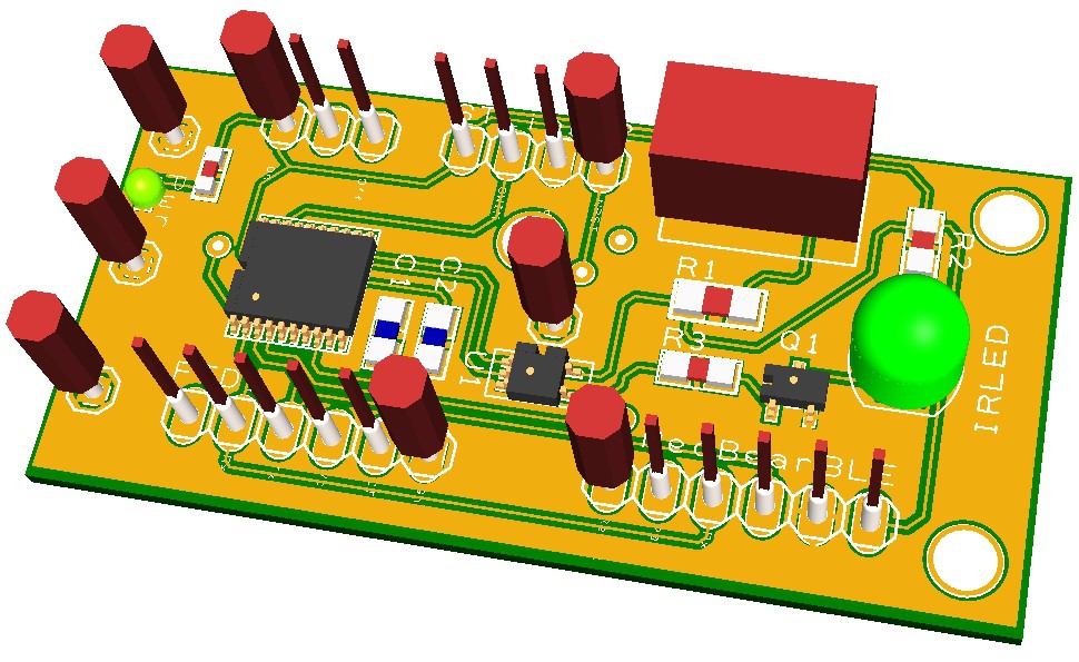
 The number of components required is small and should fit on a board which can be made using iTeads' 5cm x 5cm manufacturing process.
A few hours with Designspark and the board looks like this:
 Time to send the board of for manufacture. Next step, software development and assembly.
 Nevyn
Nevyn
Discussions
Become a Hackaday.io Member
Create an account to leave a comment. Already have an account? Log In.