-
OpenIR Rev B Boards
04/28/2015 at 19:10 • 0 commentsThe rev B boards arrived today, guess I know what the weekend has in store for me.
![]()
-
PCB Revision B
04/05/2015 at 09:31 • 0 commentsTime for a small hardware update to the OpenIR project.
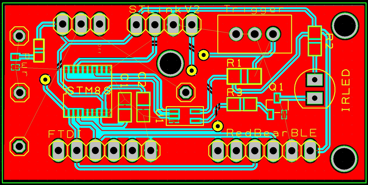
- Removed the single AND gate from the output as the pulses are now controlled purely by software
- Repositioned the Power LED
- Corrected a mistake with the positioning of the battery connections. These were Off by one
- Added some additional markings to the board for clarification
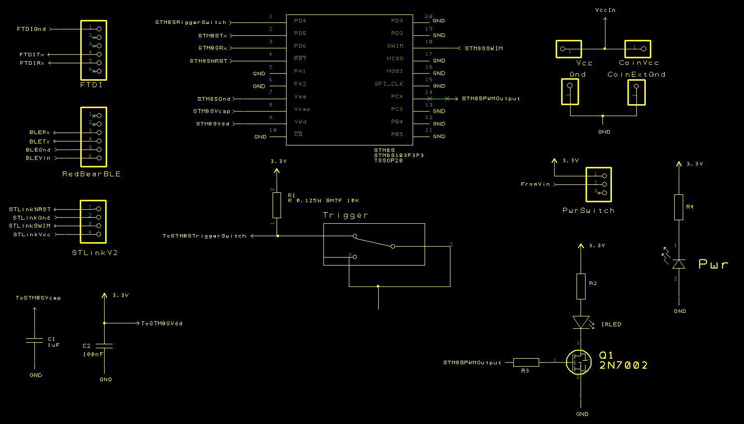
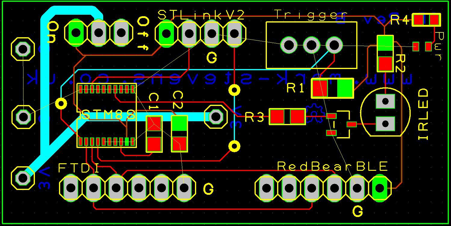
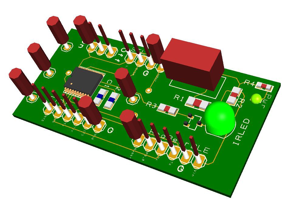
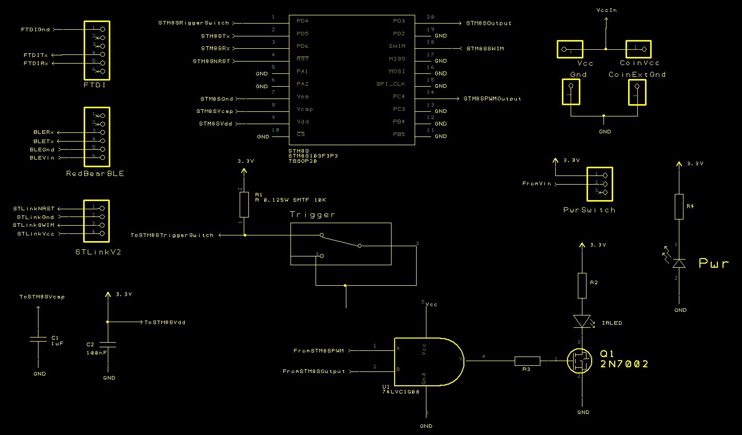
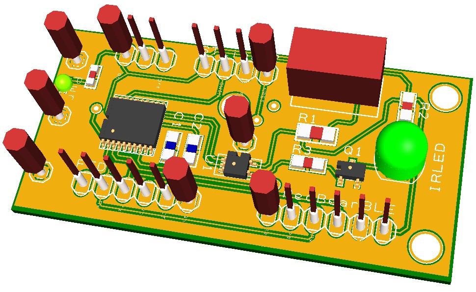
Over to the PCB manufacturer for new boards. In the meantime here are some images.
Schematic
PCB Layout![]()
![]()
3D Representaion
![]()
-
Storing Pulse Sequences
02/22/2015 at 16:58 • 0 commentsThe OpenIR application can now store and retrieve the contents of the EEPROM. The previous article demonstrated how the basic IR parameters can be stored and retrieved from the STM8S EEPROM. It is now time to start to store and retrieve command / pulse sequences in the EEPROM ready for the STM8S to process.
In the January design update a template for the EEPROM layout was presented. The final part of the EEPROM was the pulse sequences data. What has become apparent is that in addition to the pulse count data we should also be storing a meaningful name for the command. The names are not required by the STM8S as it can simply take a command number but they make the commands more meaningful when viewed in the Windows application. It is for this reason that we need to store the command name in the remote control.
Pulse Sequence Length Table
The Pulse Sequence Length table contains a list of the number of bytes in each pulse sequence. Each entry gives the offset from the start of the pulse data for each of the commands the remote control can transmit to a remote device.
The pulse data table contains the information about the commands themselves. The first eight bytes contain the name of the command. The STM8S will ignore this as it is not needed in order to transmit the command to the remote device. The next byte contains the number of pulses/transitions in the command. The following pairs of bytes contain the counter values for the timer on the STM8S. The counter values determine the number of high / low sequences and their duration.
One important consideration is the length of the command name. If the name is too short then the name is not meaningful to the user, too long and the number of commands is reduced and the STM8S may become unusable.
Editing Pulses in the Configuration Application
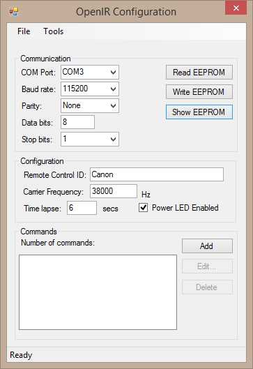
The lower part of the configuration application contains a section for the creation, modification and deletion of commands in the remote control:
![]()
Each remote control command is a series of pulses (IR signal is on) and spaces (IR signal is off). Each on /off sequence can be represented by a number of microsecond periods, the sequence starts with an on pulse and each subsequent number represents a change from on to off and so on.
Editing the wave form has been facilitated with a simple form containing a list box to hold the pulse durations and a user control presenting a graphical representation of the pulse waveform:
![]()
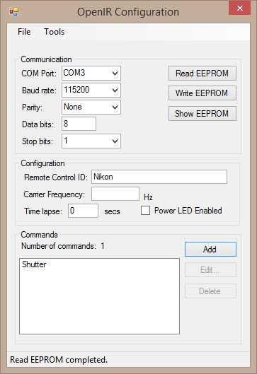
The above waveform is the sequence required to activate the shutter on a Nikon camera. Clicking on OK will add the waveform to the list of commands on the main form:
![]()
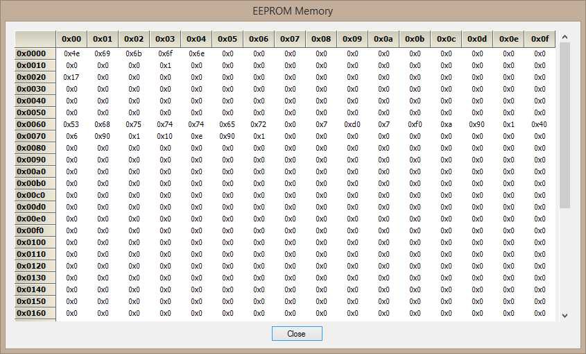
Clicking on the Show EEPROM displays the raw bytes in the EEPROM:
![]()
Conclusion
The changes to the application now allow for the storing of sequences in the EEPROM. Each command is given a name which is meaningful to the user.
The current implementation is not perfect and a number of changes are in the pipeline:
- The pulse sequences are currently stored as microsecond values. Exact counter values for Timer 2 will make the STM8S application smaller.
- Pulses are stored in the EEPROM s bytes but the configuration application uses ArrayLists and List objects for the command edit forms. It may be possible to provide a more elegant method for moving this data around the application.
-
EEPROM Memory Dump
02/15/2015 at 08:37 • 0 commentsOne debugging feature I have been keen to add is the ability to see the EEPROM memory. This will aid the debugging of the code on the STM8S as it will be easier to see the data being consumed by the application running on the remote control. The EEPROM memory dump feature simply displays a grid of memory locations along with the contents.
Main Form
The main form has been modified to take values from the user and then to translate the contents of the user controls into data for the EEPROM.
For example, the carrier frequency needs to be translated into counter values for the PWM function in Timer 1. This could be sent over to the remote control as a frequency but then it would not be possible to verify if the remote control could generate the desired frequency until the remote control tried to use the values. If the Windows application is going to perform checks on the user input then it is logical that it should send over just the counter values and not the frequency. This offloads the code necessary to perform the translation from the remote control to the user application. Doing this makes the application on the STM8S smaller. Remember, we have an 8K code limit on the remote control when using the IAR compiler.
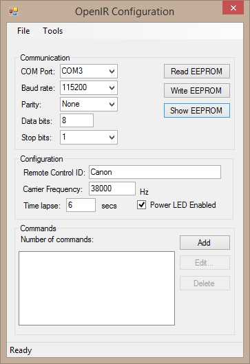
The first step is to make the controls on the user interface respond to the values being entered and also add a mechanism to show the form which will display the EEPROM memory:
![]()
EEPROM Class
The application will also need a class in order to hold the contents of the EEPROM. This class acts as an intermediary between the raw bytes in the EEPROM and the data displayed in the user controls. The properties in the class translate the bytes into data types which can be used by a C# application and visa versa.
For instance, consider the remote control name. The C# application would like to see a C# string object. In the remote control EEPROM this is a series of up to 16 bytes each holding one character. A property presents a convenient way of performing this translation. The EEPROM class will require a series of bytes to hold memroy contents:
private byte[] _memory;The Name property can then translate the C# interface requirements into those required by the STM8S application:public string Name { get { string result; if (_memory != null) { int index = NAME_OFFSET; result = ""; while ((index < NAME_LENGTH) && (_memory[index] != 0)) { result += (char) _memory[index++]; } } else { result = null; } return (result); } set { if (_memory == null) { _memory = new byte[EEPROM_LENGTH]; } if (value.Length > NAME_LENGTH) { throw new ArgumentOutOfRangeException("Name", string.Format("Name must be less than {0} characters in length.", NAME_LENGTH)); } for (int index = NAME_OFFSET; index < (NAME_OFFSET + NAME_LENGTH); index++) { if (index < value.Length) { _memory[index] = (byte) value[index]; } else { _memory[index] = 0; } } } }Similar properties can be added for the carrier frequency etc.EEPROM Form
The form displaying the EEPROM memory makes use of a Grid control in the Syncfusion Essential Studio Enterprise Edition Community edition. This suite of tools contains 650+ controls for a variety of platforms and has recently been made available at no charge to individual developers and small organisations with a low turnover (< $1m).
The form showing the EEPROM memory is simple and contains the memory contents and a button to close the form:
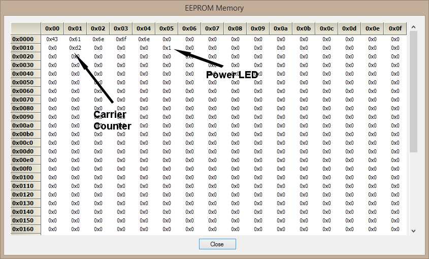
The image above shows the memory when the following properties have been set:![]()
- Name of the remote control (row 0x000, 16 bytes)
- Counter value for the PWM function on Timer1 (row 0x0010, first two bytes)
- Power LED status (row 0x0010, offset 5)
Conclusion
Development of the Windows interface is proceeding steadily. As much work as possible is being offloaded to the Windows application in order to streamline the code which needs to be written for the STM8S.
-
OpenIR Windows Configuration Application
02/01/2015 at 20:49 • 0 commentsProgress on the OpenIR project has been a little slow recently, Christmas has come and gone and now a heavy workload is slowing things down further. Having said that, today has seen the project pass another milestone with a Windows configuration application communicating with the an STM8S Discovery board over a TTL serial port.
This post will give an overview of the current progress.
Windows Configuration Application
One of the goals of the OpenIR project is to create a universal remote control. To this end the project will require a configuration application. Having a number of years experience in Windows programming it made sense for the Windows platform to host the first generation of the configuration application for the remote control.
In the previous post a number of command functions were identified as being essential to this project. The main concern for the initial development is the size of the application which IAR can support on the STM8S. This is limited to 8KB and the EEPROM transfer function is likely to consume the most memory and code space. This function has been targeted first as it is likely to identify any issues early on in the software development phase of the project.
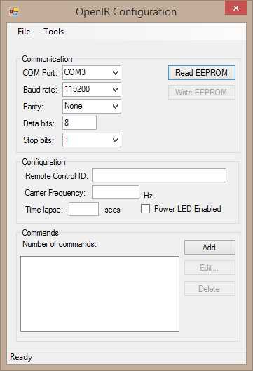
The Windows configuration application is a classic WinForms application with three distinct areas:
- Communication settings (serial port)
- General configuration
- Commands (IR sequences)
This currently looks as follows:
![]() The upper panel allows the user to select the COM port and the communication settings (baud rate, parity etc.). The two buttons allow the user to request the EEPROM data and write send the updated the EEPROM configuration back to the IR remote control module.
The upper panel allows the user to select the COM port and the communication settings (baud rate, parity etc.). The two buttons allow the user to request the EEPROM data and write send the updated the EEPROM configuration back to the IR remote control module.The middle section contains the controls which will show and allow the editing of the static configuration such as the name, carrier frequency etc.
The middle section contains the controls which will show and allow the editing of the static configuration such as the name, carrier frequency etc.
The lower panel contains the command list the remote control can send. More on this in a future post.
The current application allows the communication settings to be changed and implements the Read EEPROM request.
Data Packet Format
The initial design of the data packets allows for a request or response to be transferred with an optional data packet. The basic format is as follows:
Offset Length Description 0 1 Data packet header (0xaa) 1 2 Length of the data packet (unsigned short), high byte first. 3 1 Command to be executed. 4 n Data required for this command. 4 + n 1 Checksum for the entire packet. The packet header is an arbitrary value and 0xaa has been chosen as it is an alternating sequence of bits.
The initial design packet size was expected to be less than 256 bytes. As the design progressed it became apparent that is was desirable for the packets to be greater larger than 256 bytes.
There are a limited number of commands which have been identified for this project. At the current time this is set to be 7 and a single byte is sufficient.
The data packet is optional and in the case of the EEPROM read/write functions this will be the contents of the EEPROM either being read or written.
The checksum byte is a simple exclusive OR of all of the bytes in the packet from the initial packet header through the the end of the data packet. The starting value for the checksum is 0xaa.
The configuration application will first scan the PC for COM ports. Any available ports will be added to the drop down list of COM port names. Selecting a COM port will populate the fields with the default COM port configuration.
Clicking on the Read EEPROM button send a request to the STM8S. The STM8S will respond with the contents of the EEPROM. This can be seen in the following traces from the logic analyser.
The first trace shows the request packet (top trace) and the response from the IR remote control (lower trace):
![]() Zooming on on the request trace we can see that the command 1 (request for EEPROM data) is sent to the IR remote control:
Zooming on on the request trace we can see that the command 1 (request for EEPROM data) is sent to the IR remote control:![]() Moving along the timeline the lower trace shows the response from the module expanded:
Moving along the timeline the lower trace shows the response from the module expanded:![]() Conclusion
ConclusionThe initial communications with the IR remote control and a PC has been successful. At this point in time the source code requires some clean up work. The next step is to enhance the EEPROM configuration allowing the EEPROM to be rewritten upon command from the Windows configuration application.
-
OpenIR Software Design Update
01/04/2015 at 10:43 • 0 commentsRevision A of the board is now working and can send a single IR sequence out to a device in the real world when the on board switch is pressed. If OpenIR is to be truly universal the system needs to be able to send a multitude of commands not just a single command. In order to do this we need to be able to store IR command sequences and also allow the user to select which IR sequence is transmitted.
The STM8S has been set up to connect the TTL serial port to the FTDI and RedBear BLE board ports. Doing this allows communication with the outside world (PC, iPhone etc.). The proposed solution uses the serial TTL port to send commands to the STM8S and for the STM8S to store details of the IR signals (carrier frequency, active period etc.) in the on chip EEPROM.
The chip along with the chosen have a limit built into them, the fact that the free version of the IAR tools have an 8 KByte limit. This limits what can be achieved on the STM8S microcontroller.
Serial Commands
The STM8S will listen on the serial TTL port for commands from the outside world. The following list of commands are proposed as a starting point:
Command ID Description 1 Get Remote control ID. This returns a text string which identified the remote control. 2 Set the remote control ID. 3 Get the carrier frequency. This gets the two bytes which are used by Timer 1 to determine the frequency of the PWM signal. 4 Set the carrier frequency. This set the two bytes which are used by Timer 1 to determine the frequency of the PWM signal. 5 Get the contents of the EEPROM pulse data store. 6 Set the contents of the EEPROM pulse data store on the STM8S. 7 Transmit pulses for sequence number x where x is the item in the payload. 8 Transmit pulses. This transmits and arbitrary sequences of pulses which are contained in the remainder of the payload. 9 Time Lapse mode. Send the pulses for sequence x after y seconds. 10 Reset the remote control. 11 Enable or disable the on board power LED. A close look at the above shows that commands 1, 3 and 4 are related as are commands 2, 4 and 6. They are either getting or setting blocks of memory in the STM8S EEPROM. Given the reduced memory available and the limits of the tools it may be optimal reduce this to reading and writing the contents of the EEPROM. The configuration data would be processed on a device with more memory (PC, iPhone etc.) and the EEPROM image built and transmitted to the STM8S. The STM8S then simply needs to update the EEPROM. The final command set becomes:
Command ID Description 1 Get the contents of the EEPROM. 2 Set the contents of the EEPROM on the STM8S 3 Transmit pulses for sequence number x where x is the item in the payload. 4 Transmit pulses. This transmits and arbitrary sequences of pulses which are contained in the remainder of the payload. 5 Time Lapse mode. Send the pulses for sequence x after y seconds. 6 Reset the remote control. 7 Enable or disable the on board power LED. Layout of the EEPROM
The STM8S on the EEPROM stores the configuration of the remote control. The data stored is a mixture of basic configuration along details of the pulses for each command the remote control can transmit.
Offset Length Description 0x00 16 Text ID of the remote control 0x10 2 Two bytes which are used by Timer 1 to determine the frequency of the carrier signal. The carrier signal is assumed to be 50% duty cycle. 0x12 1 Number of command sequences stored in the EEPROM. 0x13 1 Number of seconds to use for the time lapse sequence. 0x14 12 Unused 0x20 64 Length of the pulse sequences (0x20 = length of sequence 0, 0x21 = length of sequence 1 etc.). 0x40 512 Pulse data. It is assumed that the pulse sequences will start with an on period followed by and off period until the number of sequences have been consumed. Conclusion
The basic layout of the EEPROM has been determined along with a proposed command sequence. The next step is to implement the STM8S code and some sample Windows code to configure the remote control.
-
IR Commands
08/23/2014 at 18:20 • 0 commentsRevision A of the board is now working and can send a single IR sequence out to a device in the real world when the on board switch is pressed. If OpenIR is to be truly universal the system needs to be able to send a multitude of commands not just a single command. In order to do this we need to be able to store IR command sequences and also allow the user to select which IR sequence is transmitted.
The STM8S has been set up to connect the TTL serial port to the FTDI and RedBear BLE board ports. Doing this allows communication with the outside world (PC, iPhone etc.). The proposed solution uses the serial TTL port to send commands to the STM8S and for the STM8S to store details of the IR signals (carrier frequency, active period etc.) in the on chip EEPROM.
Serial Commands
The STM8S will listen on the serial TTL port for commands from the outside world. The following list of commands are proposed as a starting point:
Command ID Description 1 Get Remote control ID. This returns a text string which identified the remote control. 2 Set the remote control ID. 3 Get the carrier frequency. This gets the two bytes which are used by Timer 1 to determine the frequency of the PWM signal. 4 Set the carrier frequency. This set the two bytes which are used by Timer 1 to determine the frequency of the PWM signal. 5 Get the contents of the EEPROM pulse data store. 6 Set the contents of the EEPROM pulse data store on the STM8S. 7 Transmit pulses for sequence number x where x is the item in the payload. 8 Transmit pulses. This transmits and arbitrary sequences of pulses which are contained in the remainder of the payload. 9 Time Lapse mode. Send the pulses for sequence x after y seconds. 10 Reset the remote control. 11 Enable or disable the on board power LED. Layout of the EEPROM
The STM8S on the EEPROM stores the configuration of the remote control. The data stored is a mixture of basic configuration along details of the pulses for each command the remote control can transmit.
Offset Length Description 0x00 16 Text ID of the remote control 0x10 2 Two bytes which are used by Timer 1 to determine the frequency of the carrier signal. The carrier signal is assumed to be 50% duty cycle. 0x12 1 Number of command sequences stored in the EEPROM. 0x13 1 Number of seconds to use for the time lapse sequence. 0x14 12 Unused. 0x20 64 Length of the pulse sequences (0x20 = length of sequence 0, 0x21 = length of sequence 1 etc.). 0x60 512 Pulse data. It is assumed that the pulse sequences will start with an on period followed by and off period until the number of sequences have been consumed. Conclusion
The basic layout of the EEPROM has been determined along with a proposed command sequence. The next step is to implement the STM8S code and some sample Windows code to configure the remote control.
-
GitHub Repository Created
08/10/2014 at 08:32 • 0 commentsToday has seen the creation of a Github repository for the hardware design files and the source code for this project.
The hardware has been designed using DesignSpark's free PCB design tools. This is a great little tool and is free to download and use. The tool has a large number of component models including some 3D models for the components. If a component is not available as a model then you can create a new part easily. I prefer this tool to may of the alternatives as it is the most Windows like PCB editing tool available and best of all it's FREE!
Source code will start appearing over the next few days. Initially the development will focus on the STM8S as this is key to the endeavour.
I have also posted links to several of the tools which are required in order to build the hardware and software in this project. You can find these in the links section of the project.
-
Making the Circuit more Permanent
08/02/2014 at 17:09 • 0 commentsThe tests so far have proven that the theory can be realised and so it is time to make the circuit more permanent. First task, move the circuit from breadboard to proto/perf board.
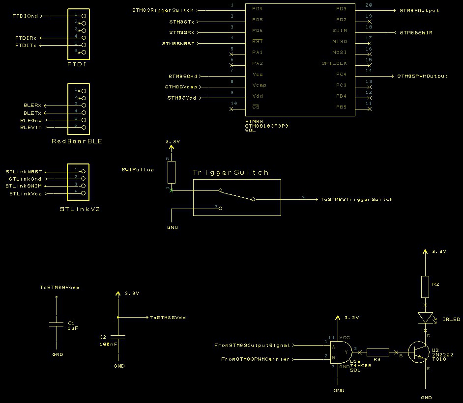
The layout is nothing too complex and can be constructed out on a moderate sized piece board. The task is to translate the schematic:
![]() into a working board.
into a working board.There are plenty of resources on the web to aid in the translation of the circuit into a working prototype so I won't cover this topic here. After a few hours with the soldering iron and the components bin I ended up with the following:
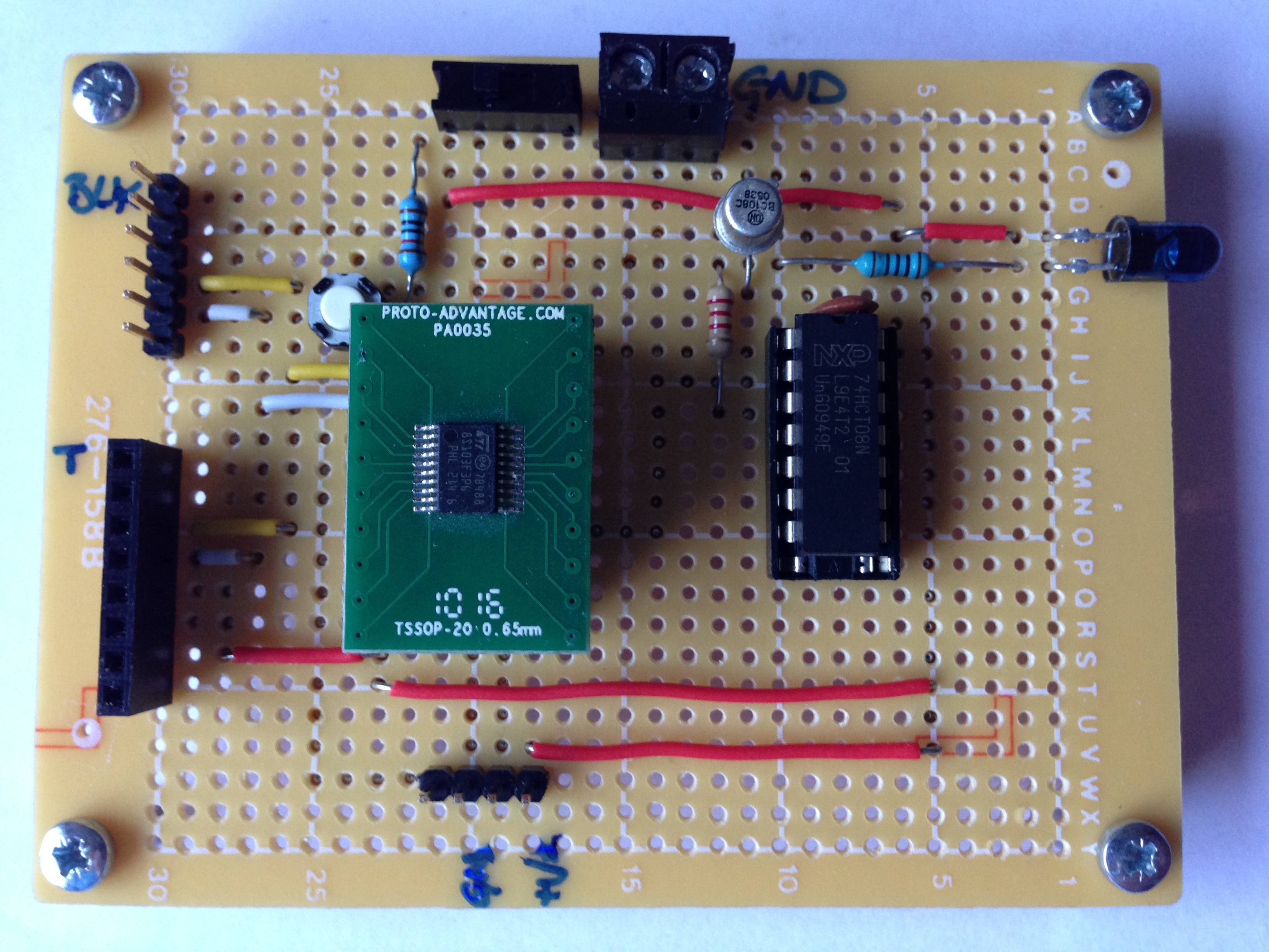
![]() The two connectors to the left of the board are the TTL serial (top male) and RedBear BLE (bottom female) connectors. The connector on the lower part of the board allows the connection of the STLink/V2 programmer to the STM8S.
The two connectors to the left of the board are the TTL serial (top male) and RedBear BLE (bottom female) connectors. The connector on the lower part of the board allows the connection of the STLink/V2 programmer to the STM8S.A quick test shows that the software still works. I now have a more permanent prototype to work with.
Manufacturing a PCB
Whilst the board above is OK for prototyping the circuit is intended to end up on a manufactured PCB. A quick look at the schematic and we find we should add some additional parts:
- Connection points for power (options for bench supply, coin cell and 2 x AA battery)
- Power LED to indicate if the board is powered
- Single AND gate to replace the four AND gate package used above
- Ground any unused pins
Making these modifications results in the following schematic:
![]() The number of components required is small and should fit on a board which can be made using iTeads' 5cm x 5cm manufacturing process.
The number of components required is small and should fit on a board which can be made using iTeads' 5cm x 5cm manufacturing process.A few hours with Designspark and the board looks like this:
![]() Time to send the board of for manufacture. Next step, software development and assembly.
Time to send the board of for manufacture. Next step, software development and assembly.![]()
-
Modulating the Signal
07/22/2014 at 12:46 • 0 commentsThe infrared signals from a remote control are normally carried on a modulated signal of around 38 - 40 KHz. The aim of this stage of the project is to add modulation to the digital signals generated in the last stage of the project.
How Does Modulation Work?
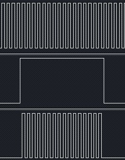
Modulation works by turning on the carrier signal when we need a logic one to be output and turned off when the digital signal should be logic zero. This is best illustrated with some pictures.
Digital signal:
![]()
Carrier signal (38 KHz):
![]()
Combined output:
![]() The lower trace shows how the carrier signal is only output when a digital one is to be generated. At all other times the output remains at logic zero.
The lower trace shows how the carrier signal is only output when a digital one is to be generated. At all other times the output remains at logic zero.The modulation is required to help devices detecting infrared signals from remote controls differentiate the remote control signal from the ambient infrared radiation in the environment from sources such as sun light.
Hardware Changes
The modulation can be generated using a PWM signal with a 50% duty cycle. This is something which is easy to generate on the STM8S. The signal output could then the turned on and off by using the timer interrupt discussed in the last post.
A simple AND gate can be used to combine the digital output signal with a PWM signal:
![]() A single AND gate is available in surface mount form but a standard 74HCT08 quad AND gate can be used for the prototype.
A single AND gate is available in surface mount form but a standard 74HCT08 quad AND gate can be used for the prototype.Software Changes
The software used in the last post can be reused with minor modifications. The first task is to generate a 38.4 KHz PWM signal. This can be achieved using one of the other timers on the STM8S103, namely timer 1, channel 4.
Using the default HSI clock of 2MHz the peak to peak duration of the PWM signal is 26uS. This is equivalent to 52 clock pulses on the 2MHz system clock. This results in the following setup code for Timer 1:
//--------------------------------------------------------------------------------
//
//  Set up Timer 1, channel 4 to output a single pulse lasting 240 uS.
//
void SetupTimer1()
{
    TIM1_ARRH = 0x00;       //  Reload counter = 51
    TIM1_ARRL = 0x33;
    TIM1_PSCRH = 0;         //  Prescalar = 0 (i.e. 1)
    TIM1_PSCRL = 0;
    //
    //  Now configure Timer 1, channel 4.
    //
    TIM1_CCMR4_OC4M = 7;    //  Set up to use PWM mode 2.
    TIM1_CCER2_CC4E = 1;    //  Output is enabled.
    TIM1_CCER2_CC4P = 0;    //  Active is defined as high.
    TIM1_CCR4H = 0x00;      //  26 = 50% duty cycle (based on TIM1_ARR).
    TIM1_CCR4L = 0x1a;
    TIM1_BKR_MOE = 1;       //  Enable the main output.
}
For completeness (and to save power) the PWM pulse should be turned off when it is not required. This requires a modification to the interrupt handler for Timer 2:
//--------------------------------------------------------------------------------
//
//  Timer 2 Overflow handler.
//
#pragma vector = TIM2_OVR_UIF_vector
__interrupt void TIM2_UPD_OVF_IRQHandler(void)
{
    _currentPulse++;
    if (_currentPulse == _numberOfPulses)
    {
        //
        //  We have processed the pulse data so stop now.
        //
        PD_ODR_ODR3 = 0;
        TIM2_CR1_CEN = 0;
        TIM1_CR1_CEN = 0;           //  Stop Timer 1.
    }
    else
    {
        TIM2_ARRH = _counterHighBytes[_currentPulse];
        TIM2_ARRL = _counterLowBytes[_currentPulse];
        PD_ODR_ODR3 = _outputValue[_currentPulse];
        TIM2_CR1_URS = 1;
        TIM2_EGR_UG = 1;
    }
    TIM2_SR1_UIF = 0;               //  Reset the interrupt otherwise it will fire again straight away.
}
One last change is required and that is to the main program loop, we need to turn the PWM signal on:
//--------------------------------------------------------------------------------
//
//  Main program loop.
//
void main()
{
    unsigned int pulseLength[] = { 2000U, 27830U, 400U, 1580U, 400U, 3580U, 400U };
    unsigned char onOrOff[] =    {   1,      0,     1,     0,    1,     0,    1 };
    PrepareCounterData(pulseLength, onOrOff, 7);
    __disable_interrupt();
    SetupTimer2();
    SetupTimer1();
    SetupOutputPorts();
    __enable_interrupt();
    PD_ODR_ODR3 = _outputValue[0];
    //
    //  Now we have everything ready we need to force the Timer 2 counters to
    //  reload and enable Timer 2.
    //
    TIM2_CR1_URS = 1;
    TIM2_EGR_UG = 1;
    TIM2_CR1_CEN = 1;
    TIM1_CR1_CEN = 1;       // Start Timer 1
    while (1)
    {
        __wait_for_interrupt();
    }
}
Conclusion
Connecting the logic analyser to the circuit gives the following traces:
![]() The top signal shows the carrier signal, the middle trace is the digital signal being generated and the lower trace shows the output from the AND gate and hence the LED.
The top signal shows the carrier signal, the middle trace is the digital signal being generated and the lower trace shows the output from the AND gate and hence the LED.The carrier signal looks like a solid block, zooming in on two of these blocks to the right of the trace shows the following output:
![]() This shows the at the 38.4 KHz PWM pulse is being output as required.
This shows the at the 38.4 KHz PWM pulse is being output as required.The next stage of the project requires the project move from breadboard and onto something more permanent.
OpenIR - Infrared Remote Control
Open source universal infrared remote control based upon the STM8S microcontroller with oooodles of connectivity options.
 Nevyn
Nevyn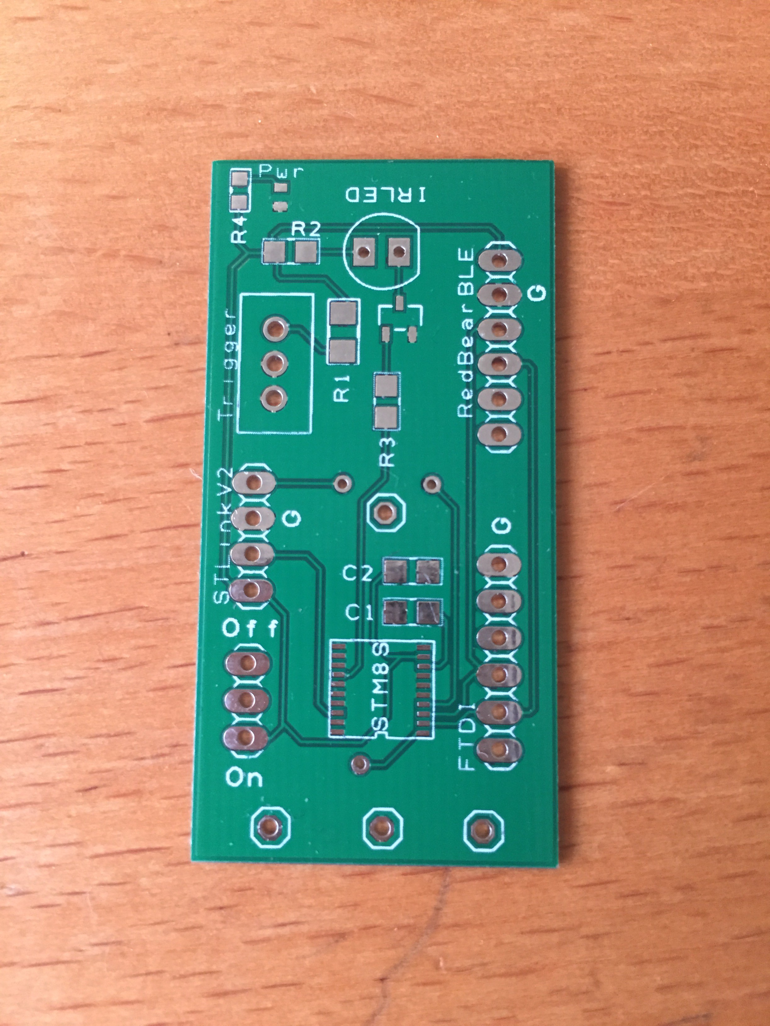

 The upper panel allows the user to select the COM port and the communication settings (baud rate, parity etc.). The two buttons allow the user to request the EEPROM data and write send the updated the EEPROM configuration back to the IR remote control module.
 Zooming on on the request trace we can see that the command 1 (request for EEPROM data) is sent to the IR remote control:
 Moving along the timeline the lower trace shows the response from the module expanded:
 Conclusion
 into a working board.
 The two connectors to the left of the board are the TTL serial (top male) and RedBear BLE (bottom female) connectors. The connector on the lower part of the board allows the connection of the STLink/V2 programmer to the STM8S.
 The number of components required is small and should fit on a board which can be made using
 Time to send the board of for manufacture. Next step, software development and assembly.

 The lower trace shows how the carrier signal is only output when a digital one is to be generated. At all other times the output remains at logic zero.
 A single AND gate is available in surface mount form but a standard 74HCT08 quad AND gate can be used for the prototype.
 The top signal shows the carrier signal, the middle trace is the digital signal being generated and the lower trace shows the output from the AND gate and hence the LED.
 This shows the at the 38.4 KHz PWM pulse is being output as required.