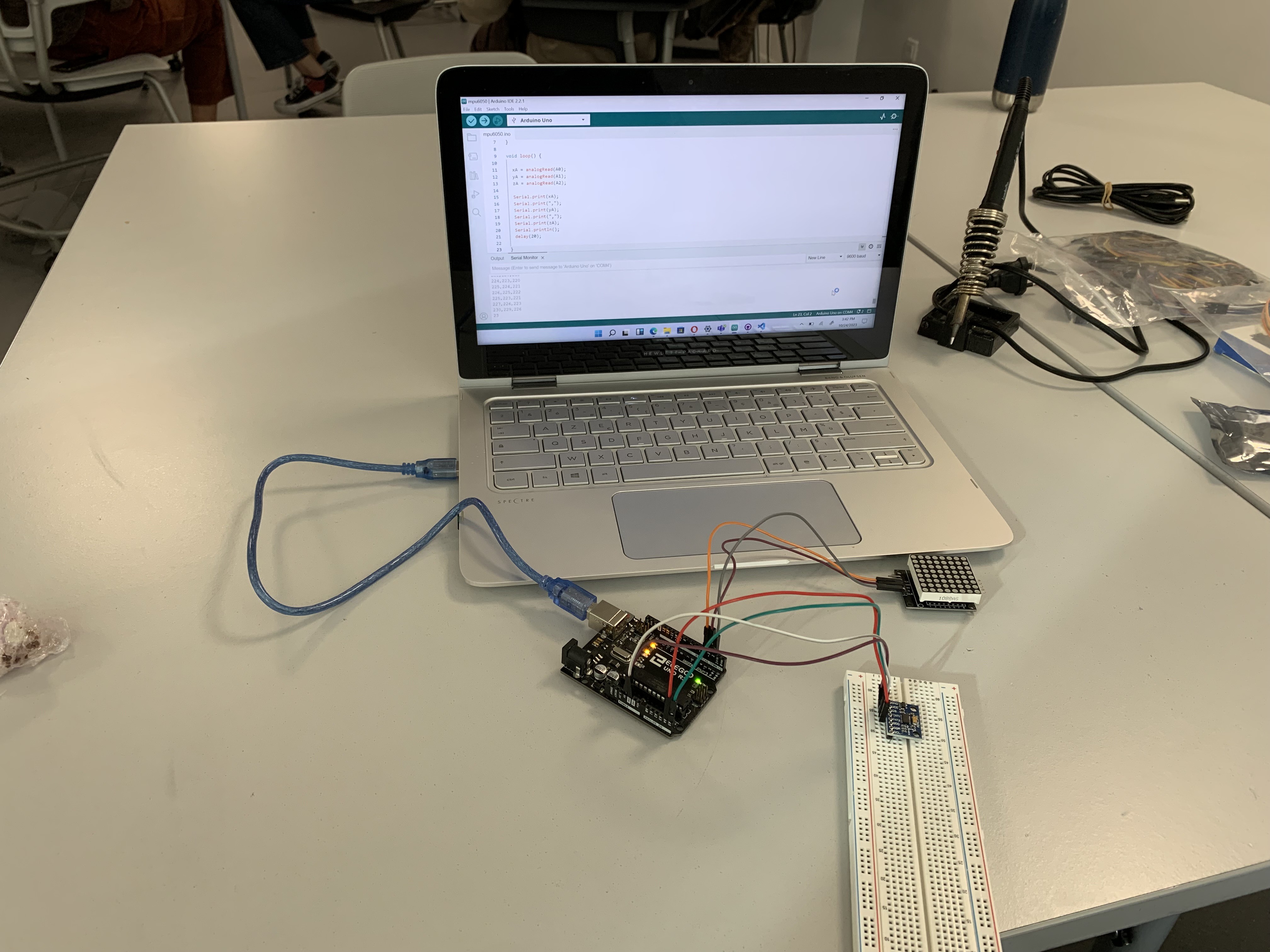
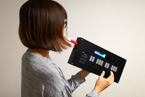
We want to create a kind of joystick, using an accelerometer, that follows the movement of our hands and that display it on a LED matrix
To make the experience fit your profile, pick a username and tell us what interests you.
We found and based on your interests.
So even after all of our effort we couldn't manage to make it work for our big LED matrix, so we went back to the simple 8x8 one. We then tried to link the speaker to the Arduino board with the LED matrix and the accelerometer, but we ran into another problem. When we tried to combine the code, which works well separately, the LED matrix wouldn't work and only the speaker would.
This is the code we used to combine the two, it compiled well but only the speaker worked.
#include <LedControl.h>
#include <Wire.h>
#define DEVICE (0x53) //ADXL345 device address
#define TO_READ (6)
#define NOTE_B0 31
#define NOTE_C1 33
#define NOTE_CS1 35
#define NOTE_D1 37
#define NOTE_DS1 39
#define NOTE_E1 41
#define NOTE_F1 44
#define NOTE_FS1 46
#define NOTE_G1 49
#define NOTE_GS1 52
#define NOTE_A1 55
#define NOTE_AS1 58
#define NOTE_B1 62
#define NOTE_C2 65
#define NOTE_CS2 69
#define NOTE_D2 73
#define NOTE_DS2 78
#define NOTE_E2 82
#define NOTE_F2 87
#define NOTE_FS2 93
#define NOTE_G2 98
#define NOTE_GS2 104
#define NOTE_A2 110
#define NOTE_AS2 117
#define NOTE_B2 123
#define NOTE_C3 131
#define NOTE_CS3 139
#define NOTE_D3 147
#define NOTE_DS3 156
#define NOTE_E3 165
#define NOTE_F3 175
#define NOTE_FS3 185
#define NOTE_G3 196
#define NOTE_GS3 208
#define NOTE_A3 220
#define NOTE_AS3 233
#define NOTE_B3 247
#define NOTE_C4 262
#define NOTE_CS4 277
#define NOTE_D4 294
#define NOTE_DS4 311
#define NOTE_E4 330
#define NOTE_F4 349
#define NOTE_FS4 370
#define NOTE_G4 392
#define NOTE_GS4 415
#define NOTE_A4 440
#define NOTE_AS4 466
#define NOTE_B4 494
#define NOTE_C5 523
#define NOTE_CS5 554
#define NOTE_D5 587
#define NOTE_DS5 622
#define NOTE_E5 659
#define NOTE_F5 698
#define NOTE_FS5 740
#define NOTE_G5 784
#define NOTE_GS5 831
#define NOTE_A5 880
#define NOTE_AS5 932
#define NOTE_B5 988
#define NOTE_C6 1047
#define NOTE_CS6 1109
#define NOTE_D6 1175
#define NOTE_DS6 1245
#define NOTE_E6 1319
#define NOTE_F6 1397
#define NOTE_FS6 1480
#define NOTE_G6 1568
#define NOTE_GS6 1661
#define NOTE_A6 1760
#define NOTE_AS6 1865
#define NOTE_B6 1976
#define NOTE_C7 2093
#define NOTE_CS7 2217
#define NOTE_D7 2349
#define NOTE_DS7 2489
#define NOTE_E7 2637
#define NOTE_F7 2794
#define NOTE_FS7 2960
#define NOTE_G7 3136
#define NOTE_GS7 3322
#define NOTE_A7 3520
#define NOTE_AS7 3729
#define NOTE_B7 3951
#define NOTE_C8 4186
#define NOTE_CS8 4435
#define NOTE_D8 4699
#define NOTE_DS8 4978
#define REST 0
// change this to make the song slower or faster
int tempo = 200;
// change this to whichever pin you want to use
int buzzer = 11;
// notes of the moledy followed by the duration.
// a 4 means a quarter note, 8 an eighteenth , 16 sixteenth, so on
// !!negative numbers are used to represent dotted notes,
// so -4 means a dotted quarter note, that is, a quarter plus an eighteenth!!
int melody[] = {
// Super Mario Bros theme
// Score available at https://musescore.com/user/2123/scores/2145
// Theme by Koji Kondo
NOTE_E5,8, NOTE_E5,8, REST,8, NOTE_E5,8, REST,8, NOTE_C5,8, NOTE_E5,8, //1
NOTE_G5,4, REST,4, NOTE_G4,8, REST,4,
NOTE_C5,-4, NOTE_G4,8, REST,4, NOTE_E4,-4, // 3
NOTE_A4,4, NOTE_B4,4, NOTE_AS4,8, NOTE_A4,4,
NOTE_G4,-8, NOTE_E5,-8, NOTE_G5,-8, NOTE_A5,4, NOTE_F5,8, NOTE_G5,8,
REST,8, NOTE_E5,4,NOTE_C5,8, NOTE_D5,8, NOTE_B4,-4,
NOTE_C5,-4, NOTE_G4,8, REST,4, NOTE_E4,-4, // repeats from 3
NOTE_A4,4, NOTE_B4,4, NOTE_AS4,8, NOTE_A4,4,
NOTE_G4,-8, NOTE_E5,-8, NOTE_G5,-8, NOTE_A5,4, NOTE_F5,8, NOTE_G5,8,
REST,8, NOTE_E5,4,NOTE_C5,8, NOTE_D5,8, NOTE_B4,-4,
REST,4, NOTE_G5,8, NOTE_FS5,8, NOTE_F5,8, NOTE_DS5,4, NOTE_E5,8,//7
REST,8, NOTE_GS4,8, NOTE_A4,8, NOTE_C4,8, REST,8, NOTE_A4,8, NOTE_C5,8, NOTE_D5,8,
REST,4, NOTE_DS5,4, REST,8, NOTE_D5,-4,
NOTE_C5,2, REST,2,
REST,4, NOTE_G5,8, NOTE_FS5,8, NOTE_F5,8, NOTE_DS5,4, NOTE_E5,8,//repeats from 7
REST,8, NOTE_GS4,8, NOTE_A4,8, NOTE_C4,8, REST,8, NOTE_A4,8, NOTE_C5,8, NOTE_D5,8,
REST,4, NOTE_DS5,4, REST,8, NOTE_D5,-4,
NOTE_C5,2, REST,2,
NOTE_C5,8,...
Read more »
While we were trying to figure out how to display it on a 4x8x32 LED matrix we decided to take a little break and try and wire the speaker to the Arduino board using a resistance. The only issue we had with this was the quality of our speaker. We ordered a cheap thin speaker and we had to be careful while handling it because the wire could easily brake. Also the quality of the speaker wasn't very good, so the sound wasn't loud enough, if you're doing this project i recommend using a better speaker.
We used this website to find the melody for the speaker.
/*
Pink Panther theme
Connect a piezo buzzer or speaker to pin 11 or select a new pin.
More songs available at https://github.com/robsoncouto/arduino-songs
Robson Couto, 2019
*/
#define NOTE_B0 31
#define NOTE_C1 33
#define NOTE_CS1 35
#define NOTE_D1 37
#define NOTE_DS1 39
#define NOTE_E1 41
#define NOTE_F1 44
#define NOTE_FS1 46
#define NOTE_G1 49
#define NOTE_GS1 52
#define NOTE_A1 55
#define NOTE_AS1 58
#define NOTE_B1 62
#define NOTE_C2 65
#define NOTE_CS2 69
#define NOTE_D2 73
#define NOTE_DS2 78
#define NOTE_E2 82
#define NOTE_F2 87
#define NOTE_FS2 93
#define NOTE_G2 98
#define NOTE_GS2 104
#define NOTE_A2 110
#define NOTE_AS2 117
#define NOTE_B2 123
#define NOTE_C3 131
#define NOTE_CS3 139
#define NOTE_D3 147
#define NOTE_DS3 156
#define NOTE_E3 165
#define NOTE_F3 175
#define NOTE_FS3 185
#define NOTE_G3 196
#define NOTE_GS3 208
#define NOTE_A3 220
#define NOTE_AS3 233
#define NOTE_B3 247
#define NOTE_C4 262
#define NOTE_CS4 277
#define NOTE_D4 294
#define NOTE_DS4 311
#define NOTE_E4 330
#define NOTE_F4 349
#define NOTE_FS4 370
#define NOTE_G4 392
#define NOTE_GS4 415
#define NOTE_A4 440
#define NOTE_AS4 466
#define NOTE_B4 494
#define NOTE_C5 523
#define NOTE_CS5 554
#define NOTE_D5 587
#define NOTE_DS5 622
#define NOTE_E5 659
#define NOTE_F5 698
#define NOTE_FS5 740
#define NOTE_G5 784
#define NOTE_GS5 831
#define NOTE_A5 880
#define NOTE_AS5 932
#define NOTE_B5 988
#define NOTE_C6 1047
#define NOTE_CS6 1109
#define NOTE_D6 1175
#define NOTE_DS6 1245
#define NOTE_E6 1319
#define NOTE_F6 1397
#define NOTE_FS6 1480
#define NOTE_G6 1568
#define NOTE_GS6 1661
#define NOTE_A6 1760
#define NOTE_AS6 1865
#define NOTE_B6 1976
#define NOTE_C7 2093
#define NOTE_CS7 2217
#define NOTE_D7 2349
#define NOTE_DS7 2489
#define NOTE_E7 2637
#define NOTE_F7 2794
#define NOTE_FS7 2960
#define NOTE_G7 3136
#define NOTE_GS7 3322
#define NOTE_A7 3520
#define NOTE_AS7 3729
#define NOTE_B7 3951
#define NOTE_C8 4186
#define NOTE_CS8 4435
#define NOTE_D8 4699
#define NOTE_DS8 4978
#define REST 0
// change this to make the song slower or faster
int tempo = 120;
// change this to whichever pin you want to use
int buzzer = 11;
// notes of the moledy followed by the duration.
// a 4 means a quarter note, 8 an eighteenth , 16 sixteenth, so on
// !!negative numbers are used to represent dotted notes,
// so -4 means a dotted quarter note, that is, a quarter plus an eighteenth!!
int melody[] = {
// Pink Panther theme
// Score available at https://musescore.com/benedictsong/the-pink-panther
// Theme by Masato Nakamura, arranged by Teddy Mason
REST,2, REST,4, REST,8, NOTE_DS4,8,
NOTE_E4,-4, REST,8, NOTE_FS4,8, NOTE_G4,-4, REST,8, NOTE_DS4,8,
NOTE_E4,-8, NOTE_FS4,8, NOTE_G4,-8, NOTE_C5,8, NOTE_B4,-8, NOTE_E4,8, NOTE_G4,-8, NOTE_B4,8,
NOTE_AS4,2, NOTE_A4,-16, NOTE_G4,-16, NOTE_E4,-16, NOTE_D4,-16,
NOTE_E4,2, REST,4, REST,8, NOTE_DS4,4,
NOTE_E4,-4, REST,8, NOTE_FS4,8, NOTE_G4,-4, REST,8, NOTE_DS4,8,
NOTE_E4,-8, NOTE_FS4,8, NOTE_G4,-8, NOTE_C5,8, NOTE_B4,-8, NOTE_G4,8, NOTE_B4,-8, NOTE_E5,8,
NOTE_DS5,1,
NOTE_D5,2, REST,4, REST,8, NOTE_DS4,8,
NOTE_E4,-4, REST,8, NOTE_FS4,8, NOTE_G4,-4, REST,8, NOTE_DS4,8,
NOTE_E4,-8, NOTE_FS4,8, NOTE_G4,-8, NOTE_C5,8, NOTE_B4,-8, NOTE_E4,8, NOTE_G4,-8, NOTE_B4,8,
NOTE_AS4,2, NOTE_A4,-16, NOTE_G4,-16, NOTE_E4,-16, NOTE_D4,-16,
NOTE_E4,-4, REST,4,
REST,4, NOTE_E5,-8, NOTE_D5,8, NOTE_B4,-8, NOTE_A4,8, NOTE_G4,-8, NOTE_E4,...
Read more »
We first tried to keep using the code we have and that works with the small LED matrix by only changing the width and a few other details of the code but that didn't work out. We spent a very long time on this because we couldn't understand why our code wouldn't work anymore. We changed the wiring multiple times thinking that was maybe our problem but it apparently wasn't. Down here is the failed code we tried for our LED matrix and the results on the LED matrix.
#include <LedControl.h>
#include <Wire.h>
#define DEVICE (0x53) // ADXL345 device address
#define TO_READ (6) // num of bytes we are going to read (two bytes for each axis)
byte buff[TO_READ]; // 6 bytes buffer for saving data read from the device
int MATRIX_WIDTH = 8;
int MATRIX_HEIGHT = 32; // Change to 32 for an 8x32 matrix
LedControl lc = LedControl(12, 11, 10, 1); // DIN, CLK, CS, NRDEV
unsigned long delaytime = 50;
int x_key = A1;
int y_key = A0;
int x_pos;
int y_pos;
class Grain
{
public:
int x = 0;
int y = 0;
int mass = 1;
};
Grain *g;
void setup()
{
g = new Grain();
ClearDisplay();
Wire.begin();
Serial.begin(9600);
writeTo(DEVICE, 0x2D, 0);
writeTo(DEVICE, 0x2D, 16);
writeTo(DEVICE, 0x2D, 8);
}
void loop()
{
int regAddress = 0x32;
int x, y;
readFrom(DEVICE, regAddress, TO_READ, buff);
x = (((int)buff[1]) << 8) | buff[0];
y = (((int)buff[3]) << 8) | buff[2];
x = map(x, -300, 300, 0, MATRIX_WIDTH);
y = map(y, -300, 300, 0, MATRIX_HEIGHT); // Adjust mapping for 8x32 matrix
Serial.print("X: ");
Serial.print(x);
Serial.print(" Y: ");
Serial.print(y);
Serial.print("\n");
ClearDisplay();
g->x = x;
g->y = y;
lc.setLed(0, g->x, g->y, true);
delay(10);
}
void ClearDisplay()
{
int devices = lc.getDeviceCount();
for (int address = 0; address < devices; address++)
{
lc.shutdown(address, false);
lc.setIntensity(address, 1);
lc.clearDisplay(address);
}
}
void writeTo(int device, byte address, byte val)
{
Wire.beginTransmission(device);
Wire.write(address);
Wire.write(val);
Wire.endTransmission();
}
void readFrom(int device, byte address, int num, byte buff[])
{
Wire.beginTransmission(device);
Wire.write(address);
Wire.endTransmission();
Wire.beginTransmission(device);
Wire.requestFrom(device, num);
int i = 0;
while (Wire.available())
{
buff[i] = Wire.read();
i++;
}
Wire.endTransmission();
}
While waiting for our big LED matrix, we decided that we would try it with only one to begin with. This was, without a doubt, our hardest step, we spent more than 10 hours on this, we tried many codes, and we downloaded many libraries, but nothing seemed to work the way we wanted it to. We were almost discouraged, and wondered if we should change our project and do something more our speed. But we kept trying, and finally we managed to have a code that works and that does what we wants it to do ( with the help of this website ). Now we have to change it to accommodate our 3x8x32 LED matrix instead of a simple 8x8.
#include <LedControl.h>
#include <Wire.h>
#define DEVICE (0x53) //ADXL345 device address
#define TO_READ (6) //num of bytes we are going to read (two bytes for each axis)
byte buff[TO_READ] ; //6 bytes buffer for saving data read from the device
char str[512]; //string buffer to transform data before sending it
int MATRIX_WIDTH = 8;
LedControl lc = LedControl(12, 11, 10, 1); // DIN, CLK, CS, NRDEV
unsigned long delaytime = 50;
int x_key = A1;
int y_key = A0;
int x_pos;
int y_pos;
// object that represents a single light location
// future update with gravity
class Grain
{
public:
int x = 0;
int y = 0;
int mass = 1;
};
Grain *g;
void setup()
{
// set up a grain object
g = new Grain();
ClearDisplay();
Wire.begin(); // join i2c bus (address optional for master)
Serial.begin(9600); // start serial for output
//Turning on the ADXL345
writeTo(DEVICE, 0x2D, 0);
writeTo(DEVICE, 0x2D, 16);
writeTo(DEVICE, 0x2D, 8);
}
void loop()
{
// The first axis-acceleration-data register
int regAddress = 0x32;
int x, y, z;
readFrom(DEVICE, regAddress, TO_READ, buff); //read the acceleration data from ADXL345
// Combine the two bytes of each direction
// Least significant bit first
x = (((int)buff[1]) << 8) | buff[0];
y = (((int)buff[3]) << 8) | buff[2];
z = (((int)buff[5]) << 8) | buff[4];
// Convert the values into values that can be represented on the matrix
x = map(x, -300, 300, 0, 8);
y = map(y, -300, 300, 0, 8);
z = map(z, -300, 300, 0, 8);
//we send the x y z values as a string to the serial port
Serial.print("X: ");
Serial.print(x);
Serial.print(" Y: ");
Serial.print(y);
Serial.print(" Z: ");
Serial.print(z);
Serial.print("\n");
ClearDisplay();
// assign the grain to this location
g->x = x;
g->y = y;
lc.setLed(0, g->x, g->y, true);
//add some delay between each update
delay(10);
}
void ClearDisplay()
{
// sets up the lcd display
int devices = lc.getDeviceCount();
for (int address = 0; address < devices; address++)
{
lc.shutdown(address, false);
lc.setIntensity(address, 1);
lc.clearDisplay(address);
}
}
//Writes val to address register on device
void writeTo(int device, byte address, byte val)
{
Wire.beginTransmission(device); //start transmission to device
Wire.write(address); // send register address
Wire.write(val); // send value to write
Wire.endTransmission(); //end transmission
}
//reads num bytes starting from address register on device in to buff array
void readFrom(int device, byte address, int num, byte buff[])
{
Wire.beginTransmission(device); //start transmission to device
Wire.write(address); //sends address to read from
Wire.endTransmission(); //end transmission
Wire.beginTransmission(device); //start transmission to device
Wire.requestFrom(device, num); // request 6 bytes from device
int i = 0;
while (Wire.available()) //device may send less than requested (abnormal)
{
buff[i] = Wire.read(); // receive a byte
i++;
}
Wire.endTransmission(); //end transmission
}
The first thing we did, even before touching the LED matrix, we tried to code the accelerometer with Arduino so that it will accurately follow our movement. We tried many codes, not all of them worked and sometimes we would find a code that would work but since we didn't understand them we choose not to use them. So, we tried to write it ourselves, and with the help of this websites and YouTube videos ( here and here) , we managed to code our accelerometer.
#include <Wire.h>
int ADXL345 = 0x52;
float X_out, Y_out, Z_out; // Outputs
void setup() {
Serial.begin(9600);
Wire.begin();
Wire.beginTransmission(ADXL345);
Wire.write(0x2D);
Wire.write(8);
Wire.endTransmission();
delay(100);
}
void loop() {
// === Read acceleromter data === //
Wire.beginTransmission(ADXL345);
Wire.write(0x32);
Wire.endTransmission(false);
Wire.requestFrom(ADXL345, 6, true);
X_out = ( Wire.read()| Wire.read() << 8);
X_out = X_out/64;#+-8 sensitivity
Y_out = ( Wire.read()| Wire.read() << 8); // Y-axis value
Y_out = Y_out/64;
Z_out = ( Wire.read()| Wire.read() << 8); // Z-axis value
Z_out = Z_out/64;
Serial.print("Xa= ");
Serial.print(X_out);
Serial.print(" Ya= ");
Serial.print(Y_out);
Serial.print(" Za= ");
Serial.println(Z_out);
}
We first started by finding the composants that we needed in order to do our project. An accelerometer was the obvious choice as we needed something that will follow our movement. Then, based on what was already at our disposal, we chose to go with an LED matrix instead of joining numerous LEDs together. But, it was obviious that an 8x8 LED matrix wasn't going to be large enough to follow our movement correctly, so we ordered an 3x8x32 matrix and that should be more than enough space. Since we needed another output, we also ordered a speaker, we want the sound/music to change based on our movement ( ex : we move to the right -> the music gets higher/louder ; we move to the left -> the music gets lower/quieter ).
Create an account to leave a comment. Already have an account? Log In.
Become a member to follow this project and never miss any updates