gitmodimo
-
The 1st mixer
01/14/2017 at 13:59 • 0 commentsThe first mixer in spectrum analyzer is the one responsible for center frequency of analyzis and frequency sweeping. In advantest r4131c it is not any different. The main part responsible for correct frequency readout is controller of first local oscillator.
![]()
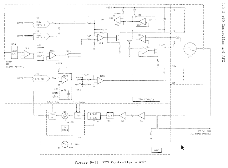
In this case (and in most cases in general) first LO is a YIG tunable oscillator. YIG technology enables the creation of voltage controlled oscillators over wide frequency range. In fact frequency of oscillation depends on magnetic field strength imposed on YIG oscillator. In order to control the magnetic field YIG oscillator is placed inside electromagnet that allows to control magnetic field and therefore frequency of oscillation. In practice the electromagnet is split into two coils. One bigger controlling most of the field strength and smaller one for fine tuning using smaller currents. This solution was also applied in Advantest spectrum analyzer. T+ T- coil is the main electromagnet and FM+ FM- is secondary used for smaller adjustments.
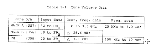
The main control over center frequency in investigated spectrum analyzer is based on 3 DACs: Main A, Main B and FM. According to documentation below and based on what is visible on schematics, the outputs of two main ADCs are added together with different weights. That gives very fine tunability of voltage over main coil. Third ADC is used to control voltage applied on secondary coil and is used for fine tuning in frequency spans lower than 10MHz.
![]()
One of main functionalities that YTO controller has to incorporate is frequency sweeping. In this case signal from ramp generator is attenuated depending on frequency span setup and is added to voltage controlling field strength. Also depending on the span signal is added to main or secondary coil.
Apart from that the schematic incorporated temperature compensation circuitry for YIG oscillator. And the missing Automated Frequency Correction (AFC) circuitry.
The difference between r4131d and r4131c is the AFC unit(missing in c version). The goal of this project is to implement that functionality into r4131c unit. While it might be possible to solder missing components (PCBs are the same) the AFC circuitry uses very old components and operates only up to 2.5GHz (analyzer operates up to 3.5GHz). Additionally there might be firmware differences that would not allow for such hack.
The idea of this project is to measure 1st LO frequency using frequency counter circuitry and tap into bus controlling the DACs. With the information of intended center frequency (DACs vaues) and actual LO frequency error can be calculated. With that error we could alter DAC values in such way that frequency error would be eliminated and thus gives the AFC functionality.
This solution seemed elegant to me, because it is all digital hack for analog problem. Original AFC circuitry (available in r4131d) consisted of PLL loop working out the correction voltage that is later added to tuning voltage.
-
Identify target
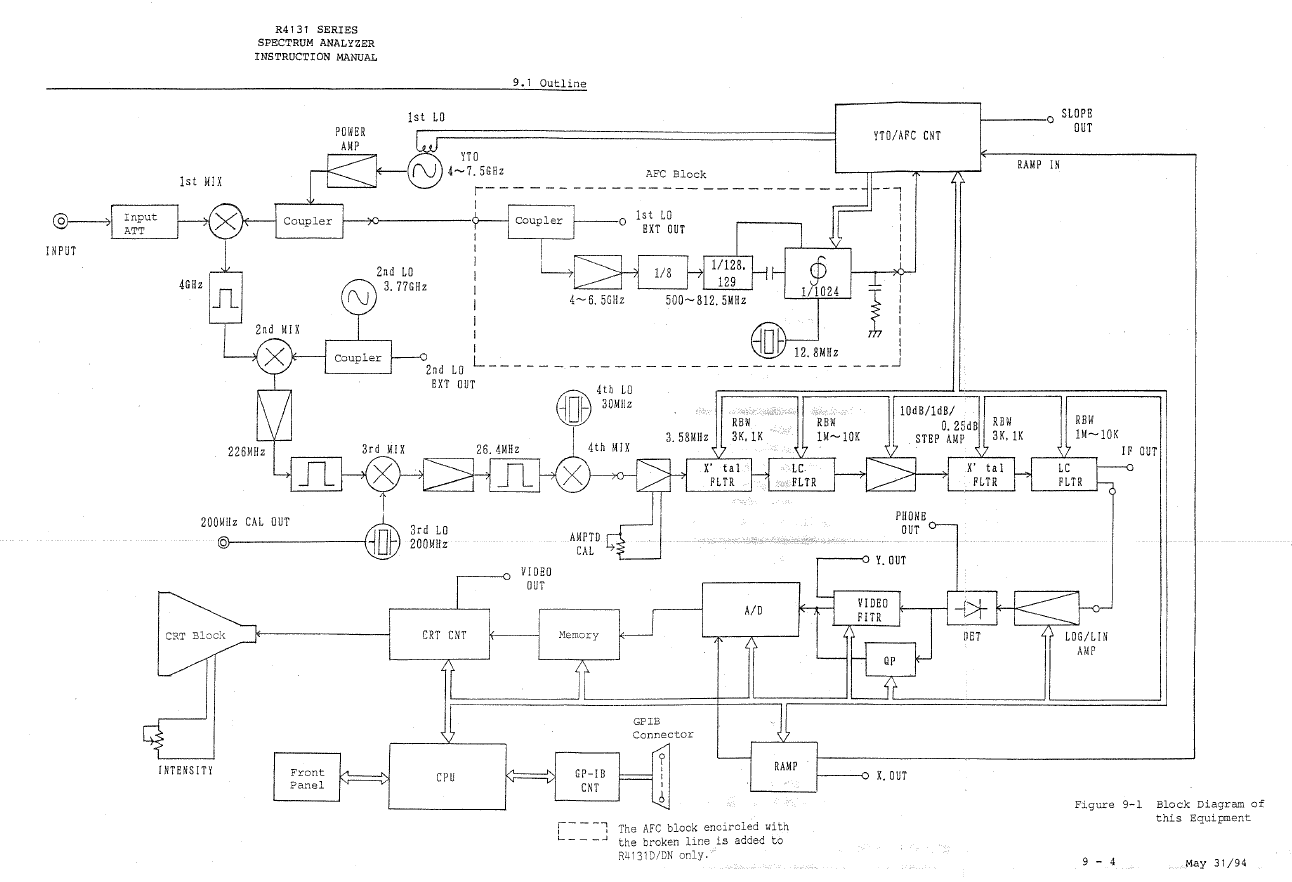
01/12/2017 at 19:32 • 0 commentsFirst of all lets start with block diagram of the analyzer.
![]()
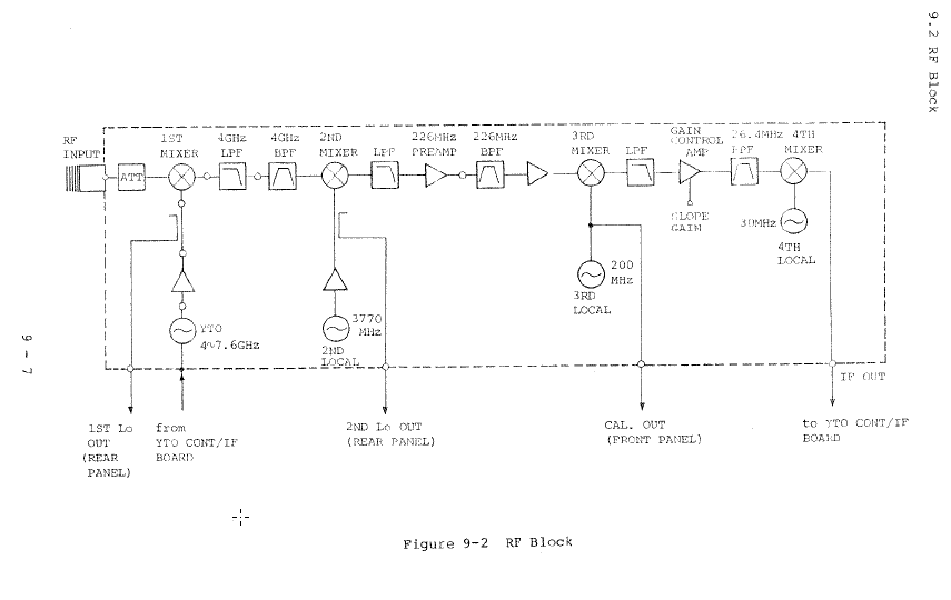
Input signal goes through input attenuator. Than 1st, 2nd 3rd and 4th mixing. So frequency instability is most likely due to local oscillators frequency drift.
More detailed block diagram shows that 3rd and 4th local oscillators are in fact crystal oscillators. So their stability should not be an issue.
![]()
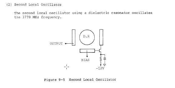
That leaves 1st and 2nd oscillator to look at. 2nd one is Dielectric Resonator Oscillator (DRO).
![]()
While its stability might be an issue, since its temperature drift might be severe, it would not correspond to observed instabilities.
That leaves 1 local oscillator as the main suspect. What is more the r4131d version that offers better frequency accuracy differs with additional AFC circuitry attached to 1st local oscillator.
That sums up problem identification.
Advantest r4131 AFC
Automatic frequency correction for Advantest spectrum analyzer