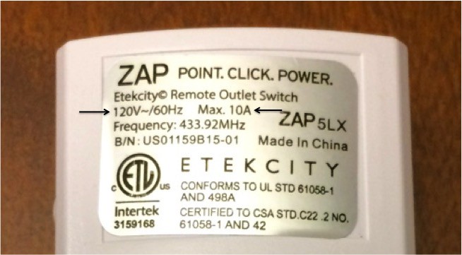
The starting outlet is intended to be used ONLY with 120V (standard US household voltage) and limited to 10 amps. As a safety factor I would not recommend drawing more than 5 amps. If you have CFL or LED light bulbs this should not be an issue however you should always calculate the circuit load before performing this project and installing. Never exceed the limits of the device. (AC Watt to Amp Calculator)
Warning: Disconnect power at circuit breaker or fuse when servicing, installing, removing and/or modifying current household wiring and/or electrical fixtures. Electrical fixtures shall be installed and/or used in accordance with appropriate electrical codes and regulations. Electricity is dangerous and can cause personal injury or death as well as other property loss or damage if not used or constructed properly. If you have any doubts what so ever about performing electrical work, hire a certified electrician to perform the work.
Warning: This project shall only be used with US standard 120V AC voltage in a 2-way circuit. The circuit created by this project shall never exceed a power output of 10A(max).
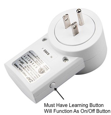
This project utilizes Etekcity's remote controlled electrical outlet switch with the learning function. You will need to be able to perform simple dis-assembly of the unit and desolder the current wiring and then solder in new wire to allow you to wire the unit in place of your two-way circuit light switch.
This project will not cover the skills of soldering and desoldering however there are plenty of instructions provided online on how to perform these tasks.
Skills
- basic soldering
- basic knowledge of using hand tools (i.e. screwdriver, drill, etc.)
- basic multi-meter operation
- household wiring
Required Tools:
- corded or cordless drill (cordless preferred)
- assorted drill bits (just drilling plastic, don't need expensive bits)
- #1 tri wing screwdriver (typically in a security bit set) or narrow flat screwdriver (from a precision screwdriver set)
- soldering iron (adjustable, 60W)
- solder sucker and/or desoldering wick
- wire cutters
- wire strippers
- x-acto knife
Recommend Tools:
- circuit board holder (recommend the PanaVise Jr.)
- helping hand (another recommendation)
Outlet Disassembly
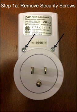
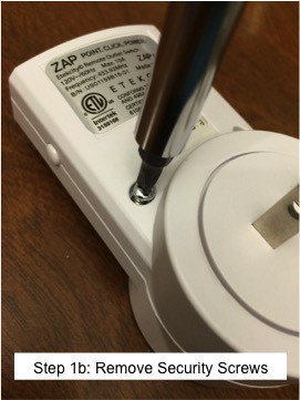
- Remove the two(2) screws from the back side of the case.
![]()
![]()
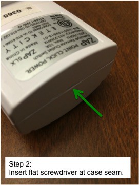
- Insert a small flat screwdriver into the top of the case.
![]()
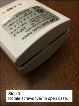
- Rotate the screwdriver to open the case.
![]()
![]()
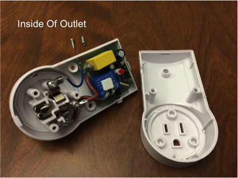
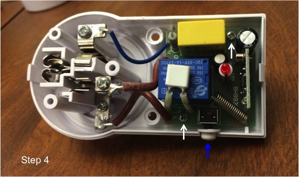
- Remove the two(2) Phillips head screws from the circuit board (white arrows). You will not save the button (blue arrow).
![]()
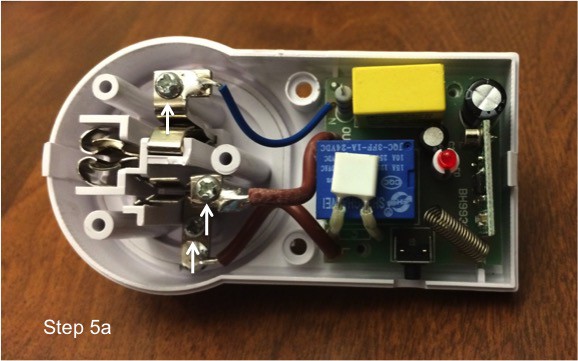
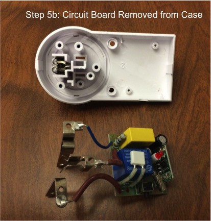
- Remove the three(3) Phillips head screws from the outlet terminals (white arrows). Remove circuit board from the case.
![]()
![]()
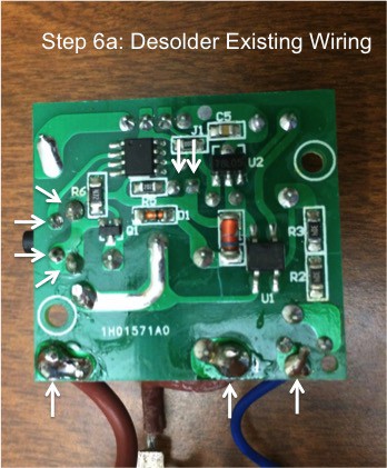
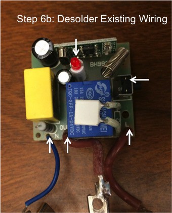
- Desolder three(3) AC power wires, LED and button from circuit board (white arrows). Remove excess solder from holes using solder sucker and/or desoldering wick. Recommend holding circuit board in vise or circuit board holder during desoldering operations.
![]()
![]()
- Cut new wire(s) to length. Recommend 6" length for UL 1015 wire and 4" length for hook-up wire, trim excess later as needed. (Note: I will be documenting the minimum length needed on a future build so you are not trimming and disposing of a ton of wire.)
- Stripe wire(s) one end only, need approx. 1/8" exposed.
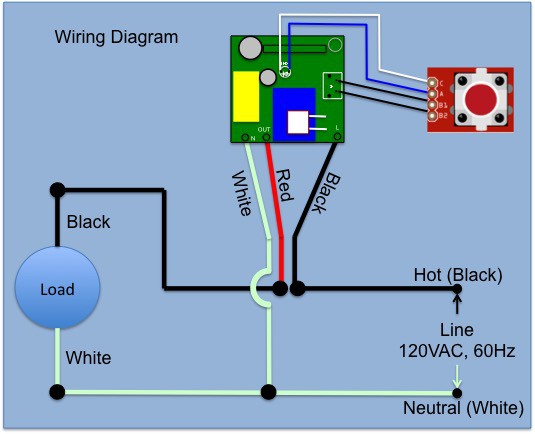
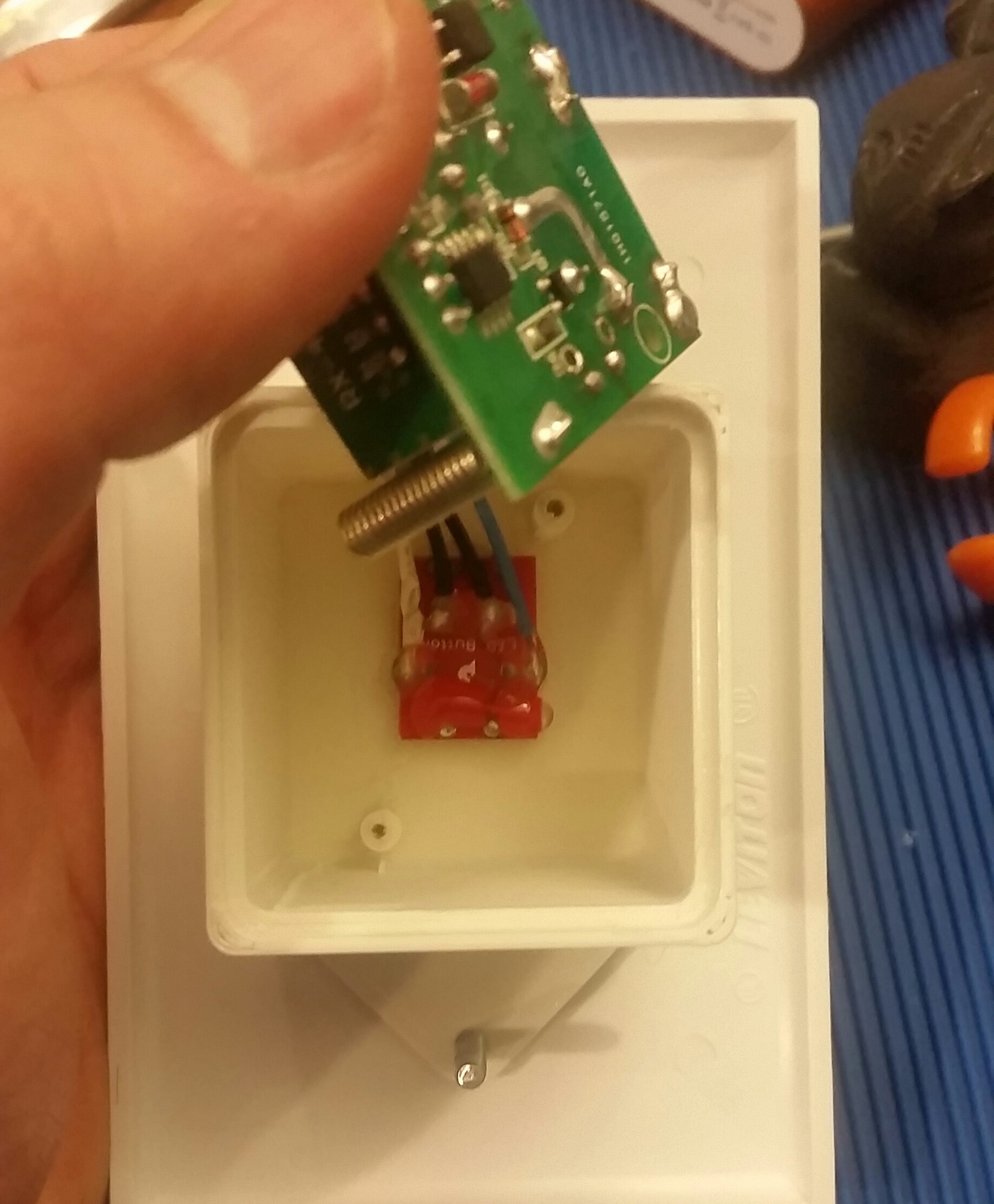
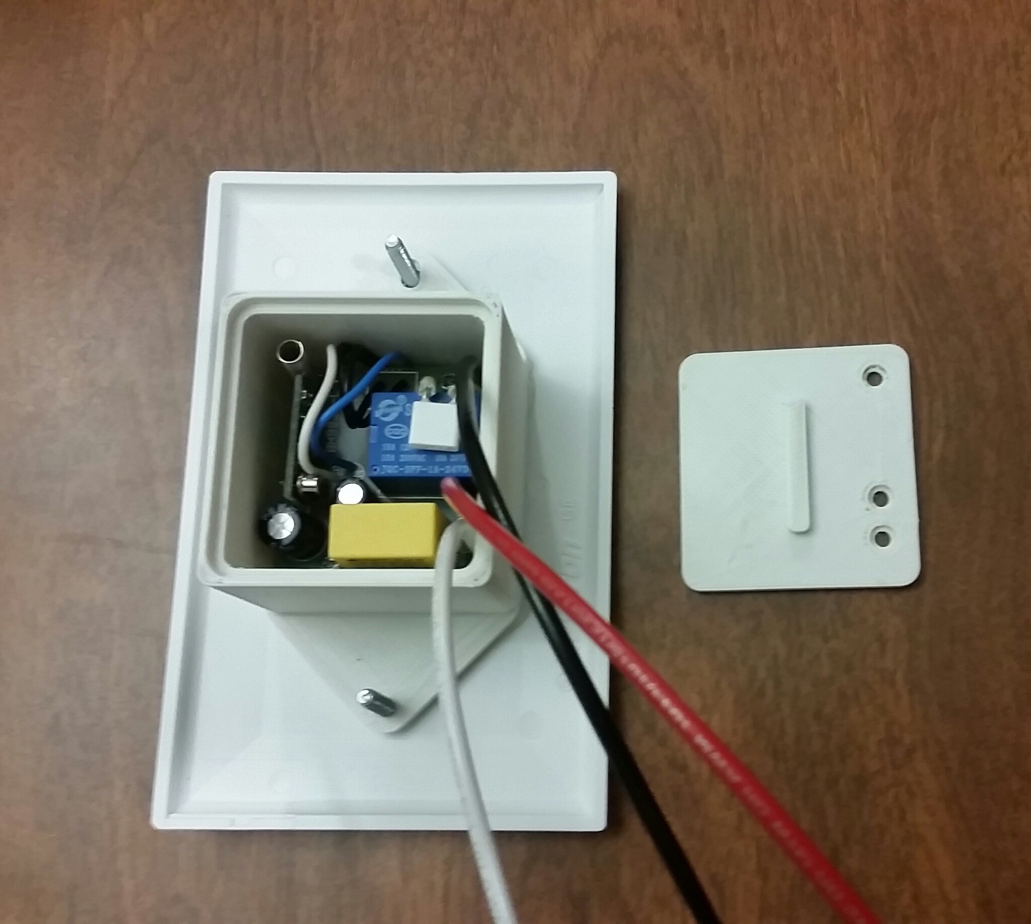
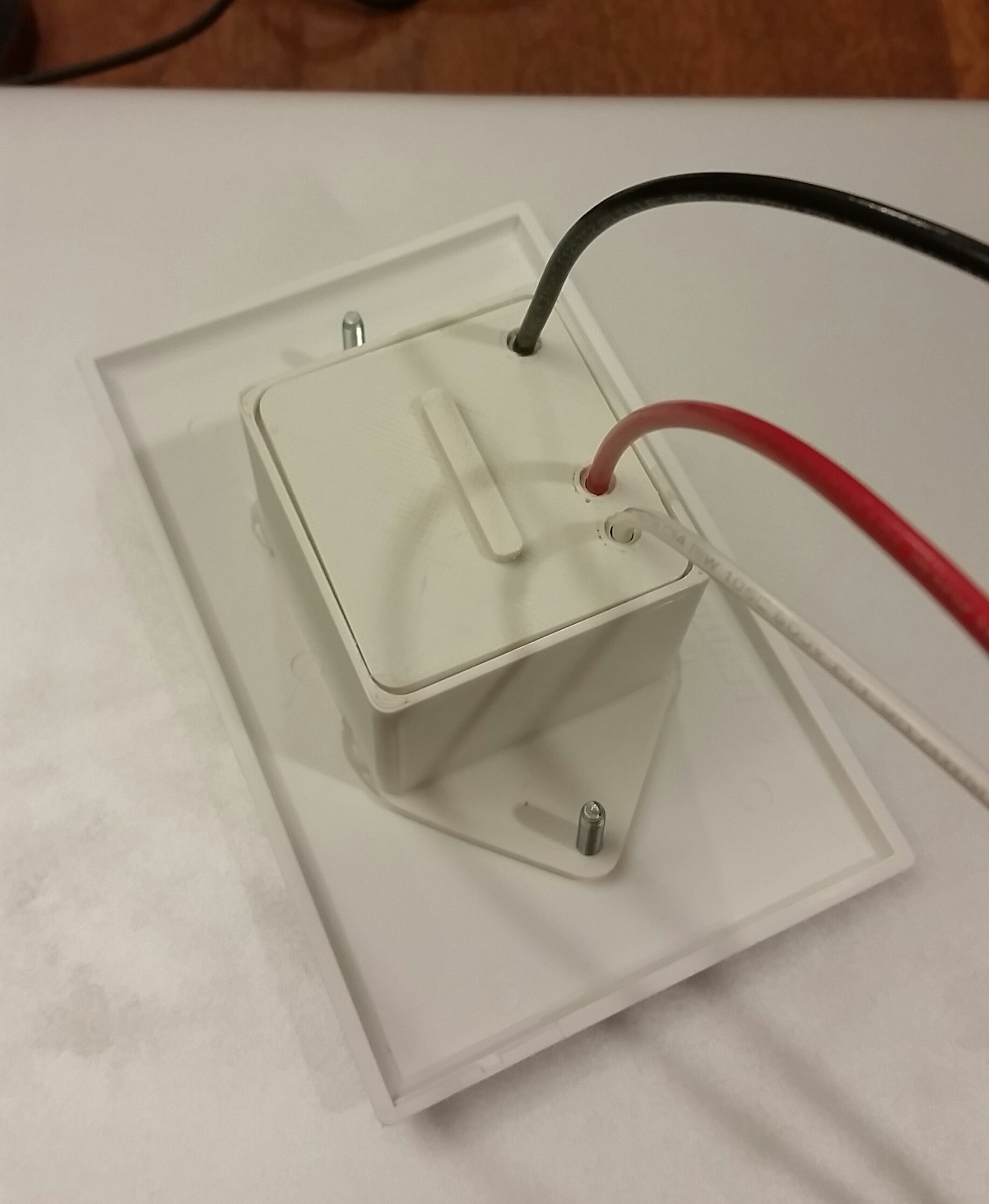
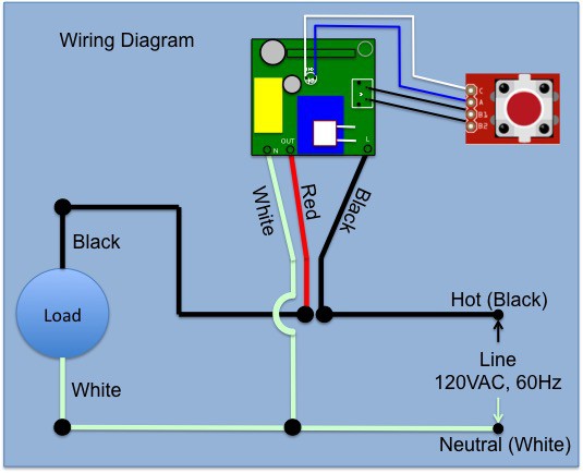
- Solder new wire(s) to circuit board. Recommend using a helping hand tool to hold wire during solder operations. Use the attached wiring diagram. To mimic the original wiring I used UL 1015 16 AWG for the red and black connections and UL 1015 18 AWG for the white connection. You can reduce your BOM costs by using one(1) color of UL 1015 16 AWG for all three(3) AC power connections one(1) color hook-up wire for the LED and button connections.
- Use multi-meter to confirm continuity of new connections.
 Eric Moyer


 Michael Aichlmayr
 Robin Hartley
 RossGK Tangibles
 Stefan-Xp
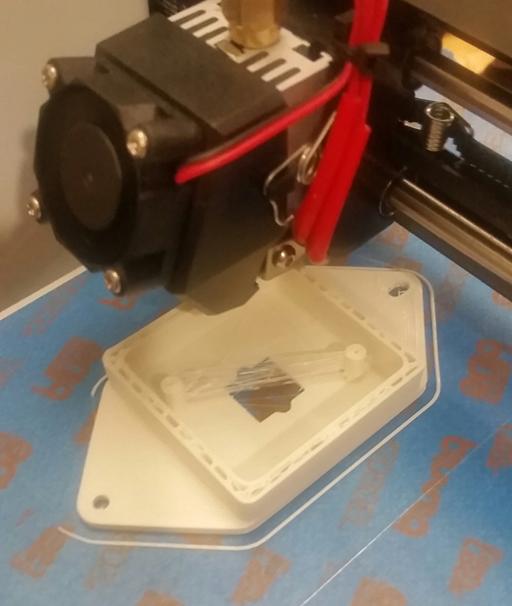
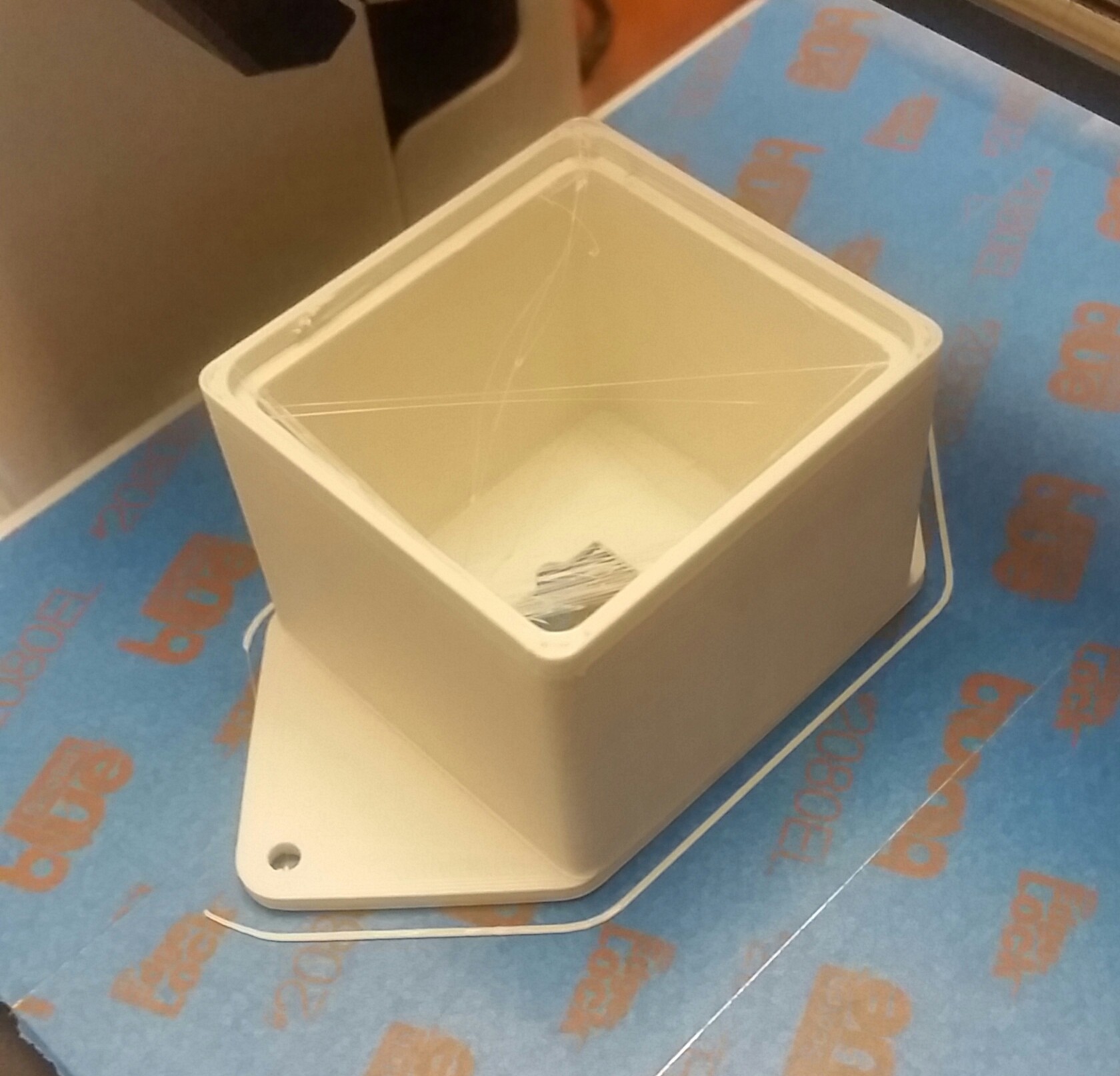
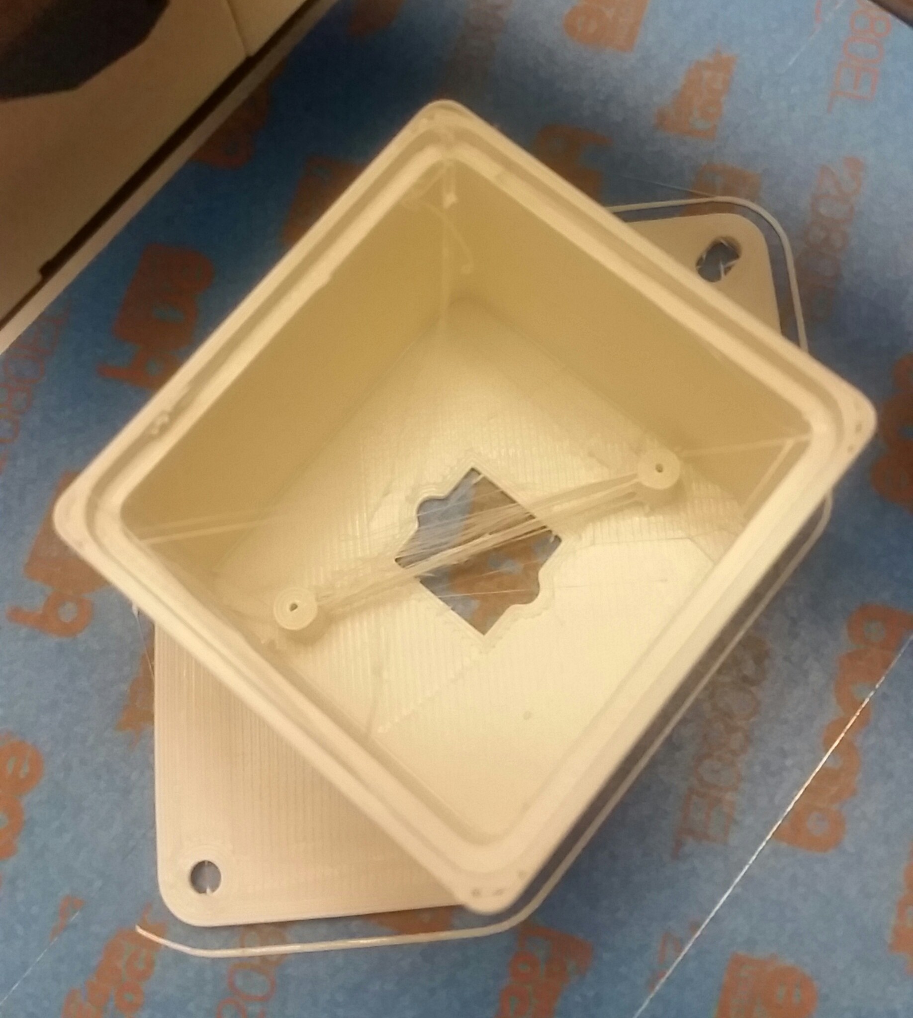
I knew there would be someone else that had the same idea i did. Great tutorial. I had taken apart one of the etekcity plugs to see how hard it would be and seems pretty straight forward especially now that i see this. Any chance you could print a housing or two for me? I don't own a printer [yet].