Close
0%
0%

RF Outlet to Light Switch Hack 2.0

Convert an off the shelf RF control outlet into a RF light switch.

Similar projects worth following
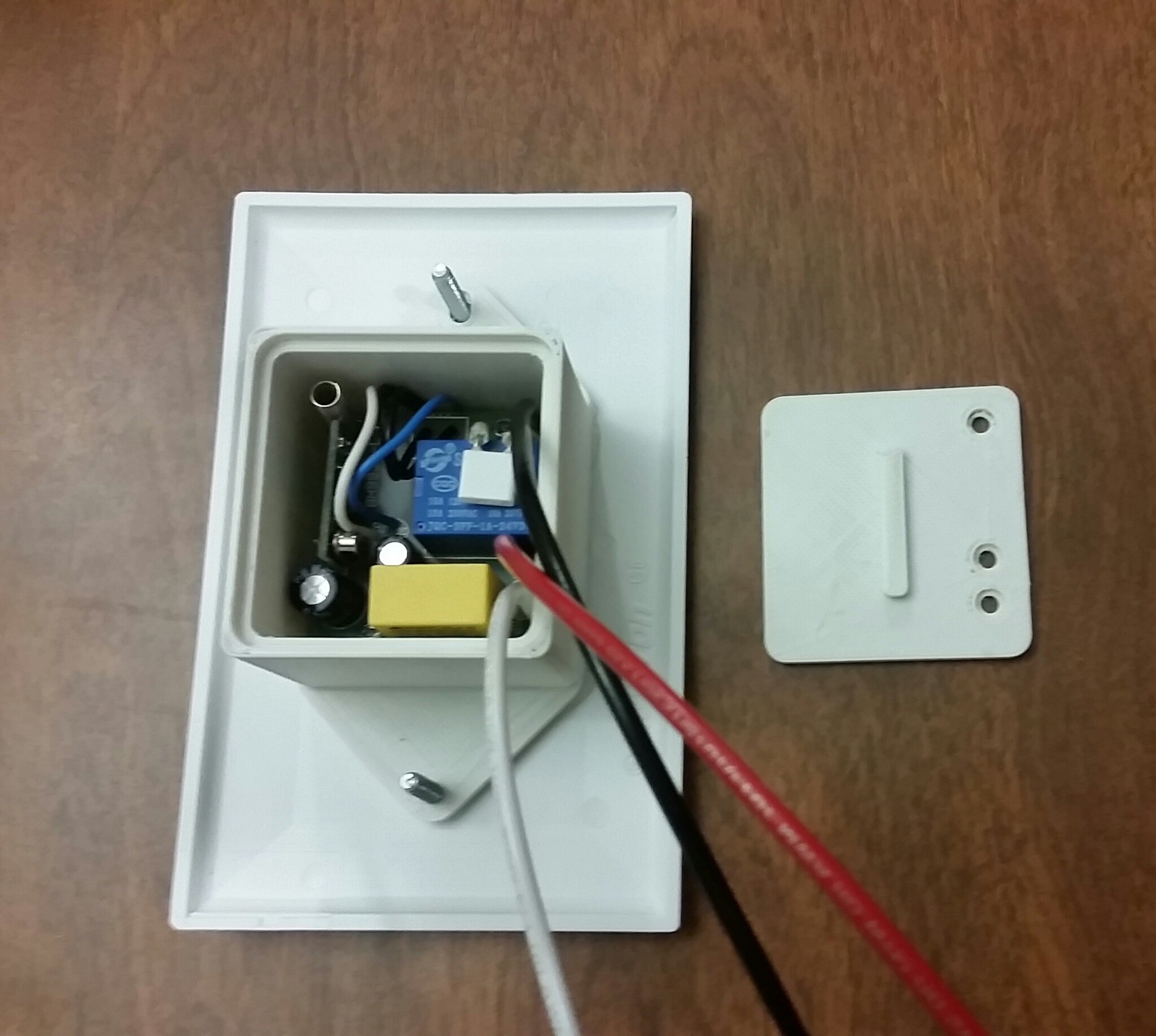
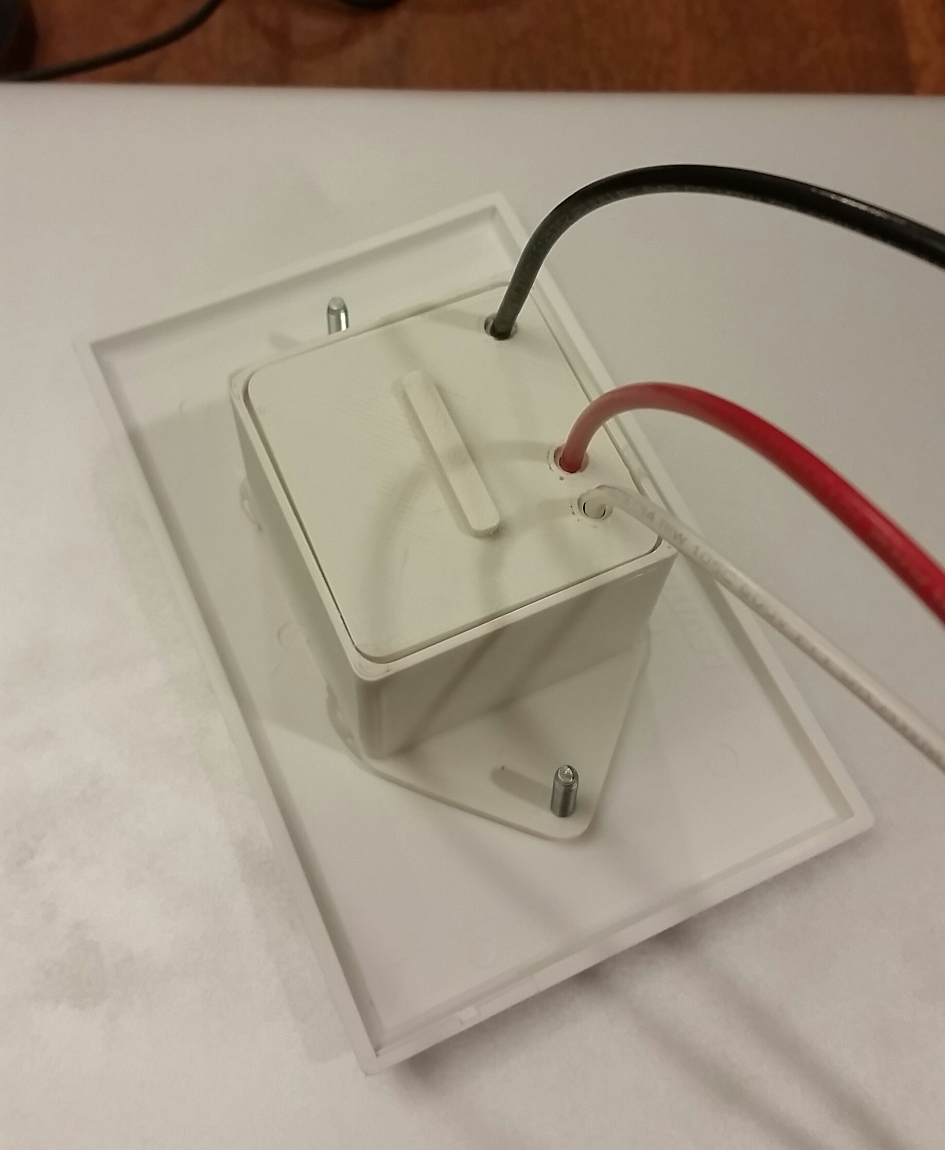
This is the continuation of a project I posted on instructables in which I did some simple modifications to convert an RF outlet into a RF light switch. The goal of this project is to safely place the electronics of the RF outlet inside a standard electrical gang box.

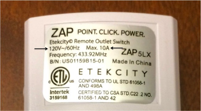
The starting outlet is intended to be used ONLY with 120V (standard US household voltage) and limited to 10 amps. As a safety factor I would not recommend drawing more than 5 amps. If you have CFL or LED light bulbs this should not be an issue however you should always calculate the circuit load before performing this project and installing. Never exceed the limits of the device. (AC Watt to Amp Calculator)

Warning: Disconnect power at circuit breaker or fuse when servicing, installing, removing and/or modifying current household wiring and/or electrical fixtures. Electrical fixtures shall be installed and/or used in accordance with appropriate electrical codes and regulations. Electricity is dangerous and can cause personal injury or death as well as other property loss or damage if not used or constructed properly. If you have any doubts what so ever about performing electrical work, hire a certified electrician to perform the work.

Warning: This project shall only be used with US standard 120V AC voltage in a 2-way circuit. The circuit created by this project shall never exceed a power output of 10A(max).
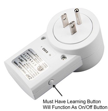
This project utilizes Etekcity's remote controlled electrical outlet switch with the learning function. You will need to be able to perform simple dis-assembly of the unit and desolder the current wiring and then solder in new wire to allow you to wire the unit in place of your two-way circuit light switch.

This project will not cover the skills of soldering and desoldering however there are plenty of instructions provided online on how to perform these tasks.

Skills

  • basic soldering
  • basic knowledge of using hand tools (i.e. screwdriver, drill, etc.)
  • basic multi-meter operation
  • household wiring

Required Tools:

  • corded or cordless drill (cordless preferred)
  • assorted drill bits (just drilling plastic, don't need expensive bits)
  • #1 tri wing screwdriver (typically in a security bit set) or narrow flat screwdriver (from a precision screwdriver set)
  • soldering iron (adjustable, 60W)
  • solder sucker and/or desoldering wick
  • wire cutters
  • wire strippers
  • x-acto knife

Recommend Tools:

Outlet Disassembly

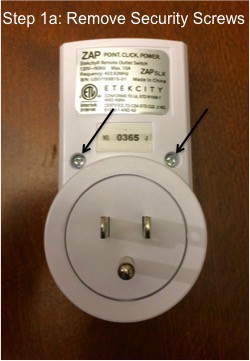
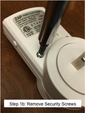
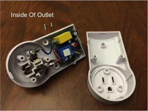
  1. Remove the two(2) screws from the back side of the case.
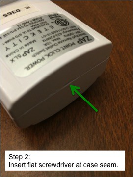
  2. Insert a small flat screwdriver into the top of the case.
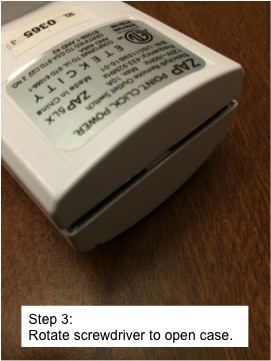
  3. Rotate the screwdriver to open the case.
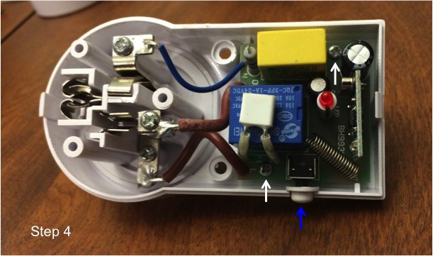
  4. Remove the two(2) Phillips head screws from the circuit board (white arrows). You will not save the button (blue arrow).
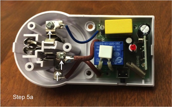
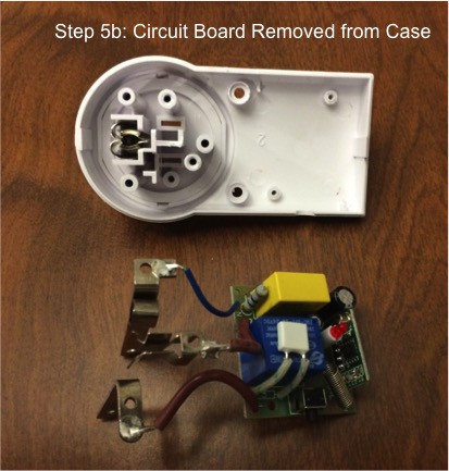
  5. Remove the three(3) Phillips head screws from the outlet terminals (white arrows). Remove circuit board from the case.
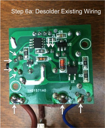
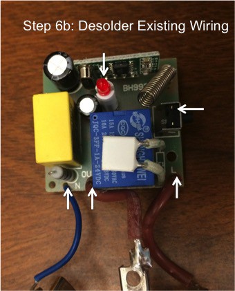
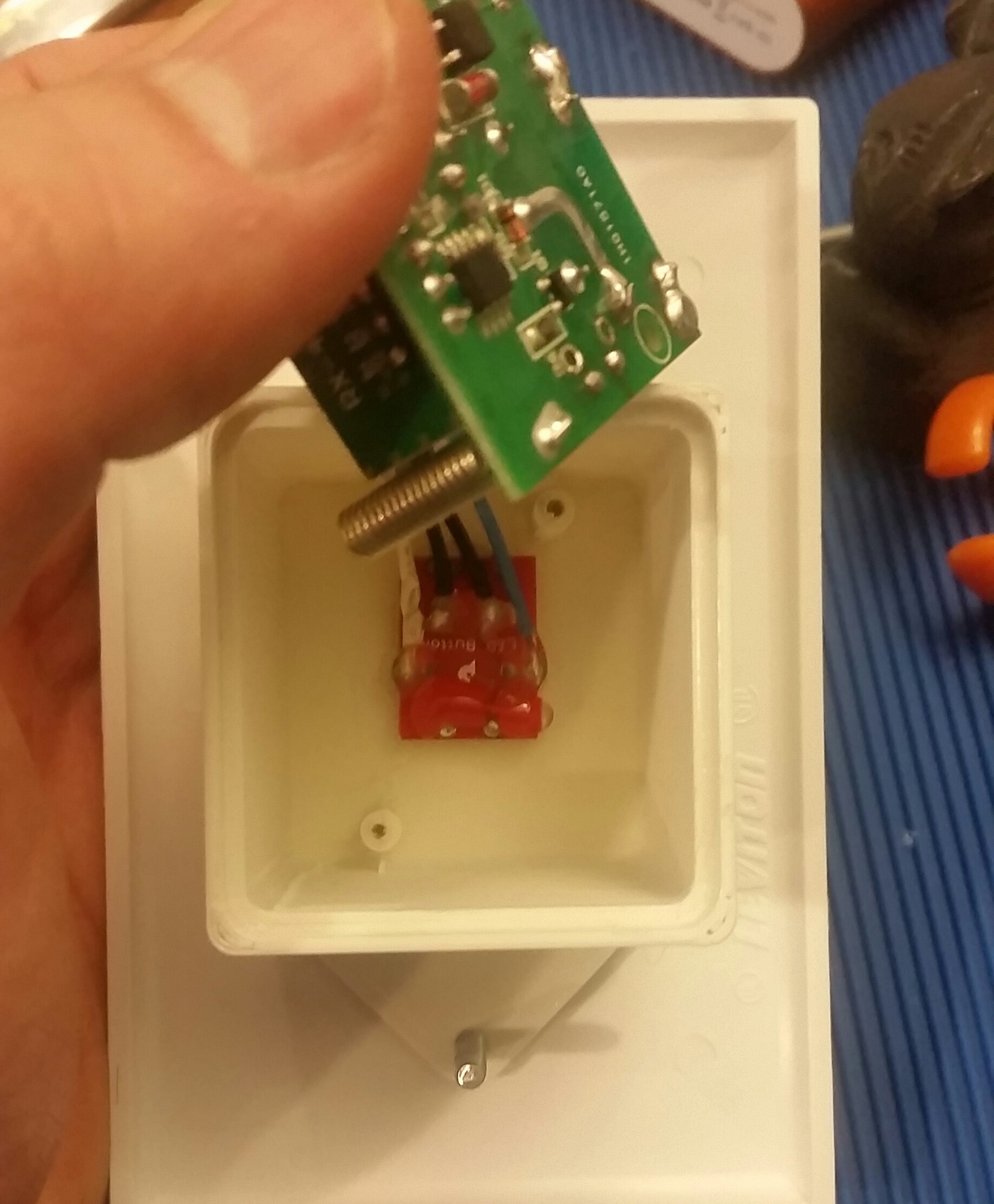
  6. Desolder three(3) AC power wires, LED and button from circuit board (white arrows). Remove excess solder from holes using solder sucker and/or desoldering wick. Recommend holding circuit board in vise or circuit board holder during desoldering operations.
  7. Cut new wire(s) to length. Recommend 6" length for UL 1015 wire and 4" length for hook-up wire, trim excess later as needed. (Note: I will be documenting the minimum length needed on a future build so you are not trimming and disposing of a ton of wire.)
  8. Stripe wire(s) one end only, need approx. 1/8" exposed.
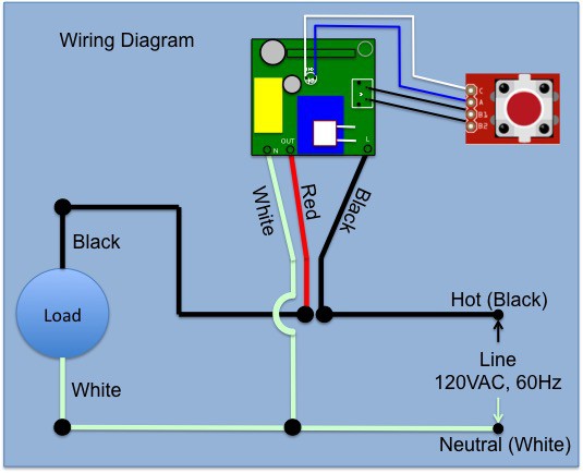
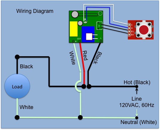
  9. Solder new wire(s) to circuit board. Recommend using a helping hand tool to hold wire during solder operations. Use the attached wiring diagram. To mimic the original wiring I used UL 1015 16 AWG for the red and black connections and UL 1015 18 AWG for the white connection. You can reduce your BOM costs by using one(1) color of UL 1015 16 AWG for all three(3) AC power connections one(1) color hook-up wire for the LED and button connections.
  10. Use multi-meter to confirm continuity of new connections.
View all 9 components

  • Switch Stopped Working

    Eric Moyer09/12/2017 at 06:45 0 comments

    About two weeks ago this project stopped working.  More specifically the lights of the room were off and when I went to turn them on only the LED switch lit up but no typical "click" from the relay to turn on the overhead lights.  I cycled the button a few times and once that didn't work I quickly shut off the breaker and removed the malfunctioning switch.  It did not trip the breaker so I suspect maybe the relay is bad.  I have yet to open the enclosure to troubleshoot since I have to fabricate a simple bench set-up to go through all the modes of failure.  My original style RF light switch hack is still working in a few other rooms for almost two years now without a single issue.

    I will post my findings once I can dedicate time to the root cause.

  • Disassembly Instructions Complete

    Eric Moyer02/22/2017 at 01:36 0 comments

    2/21/2017: I completed the instructions to disassemble the RF outlet and the wires that need to be desoldered and then replaced with new wiring that will be connected later.

  • A Change In Direction (Sort Of)

    Eric Moyer02/03/2017 at 03:29 0 comments

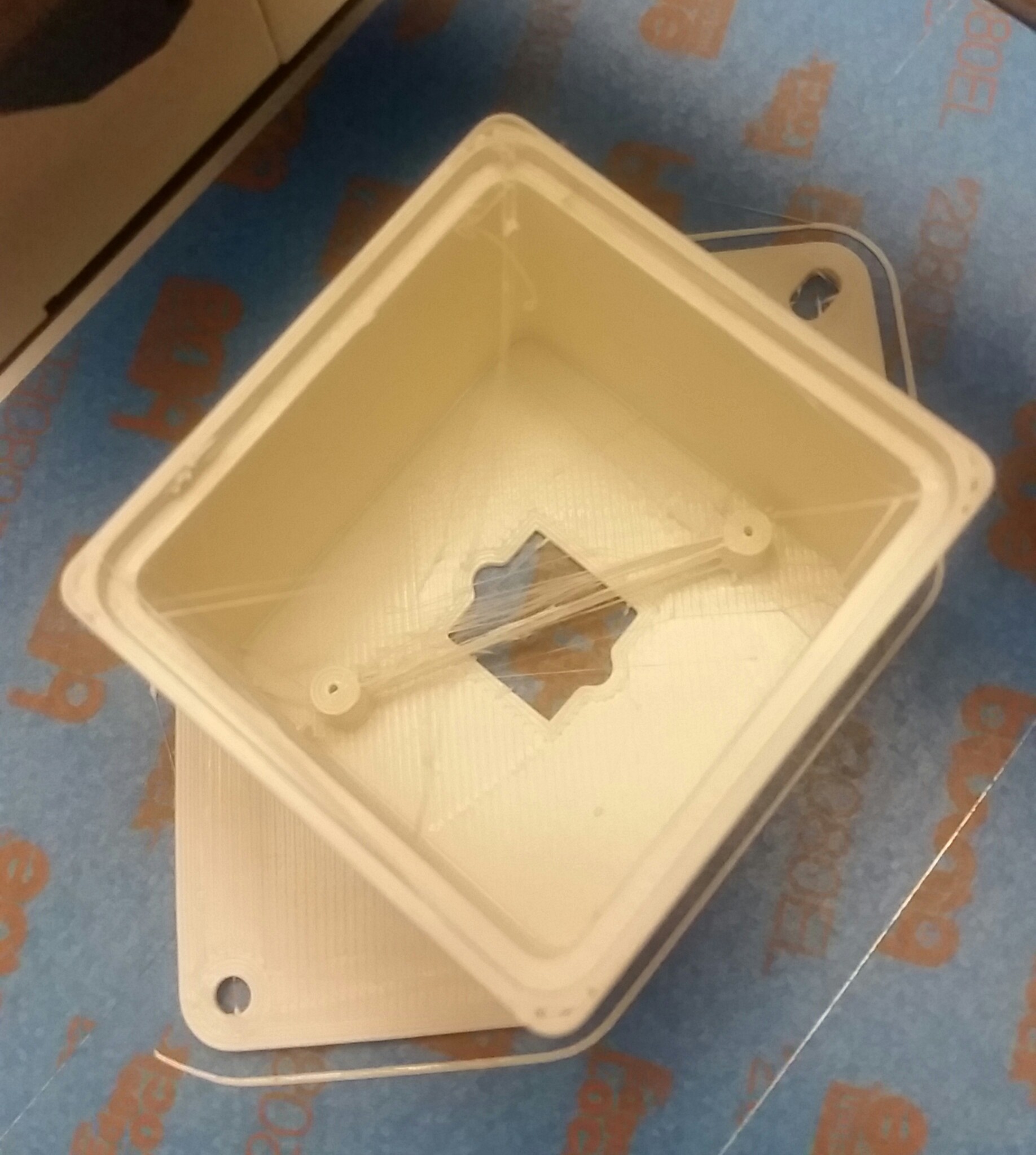
    2/2/2017: My new Monoprice Select Mini (MPSM) has really brought me back to loving 3D printing again. I always loved being able to make custom things however my older Printrbot Plus had become a chore of never ending maintenance and I quickly stopped using it when I spent more time getting it working than printing. With my MPSM I was printing right out of the box and have never looked back.

    My original idea for this project was to take the use of a 3D printer off the table since wanted to have a largest audience as possible. This presented early challenges when the off the shelf enclosure (potting box) I found wasn't making integration as easy as planned. I have decided I will still create this project with a non-3D printer option however the implementation will most likely be for single gang light switches, not the end of the world but not meeting my original goal.

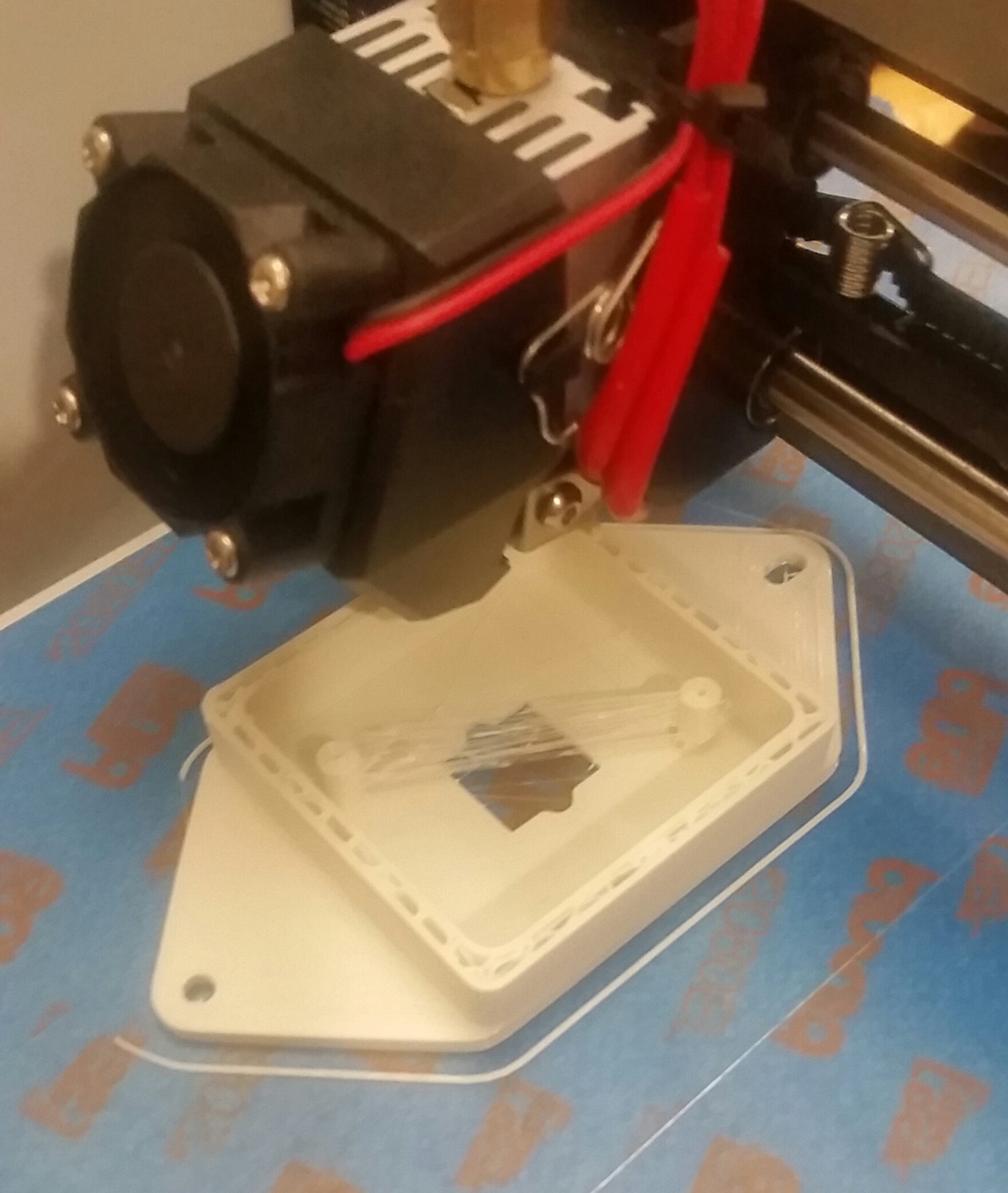
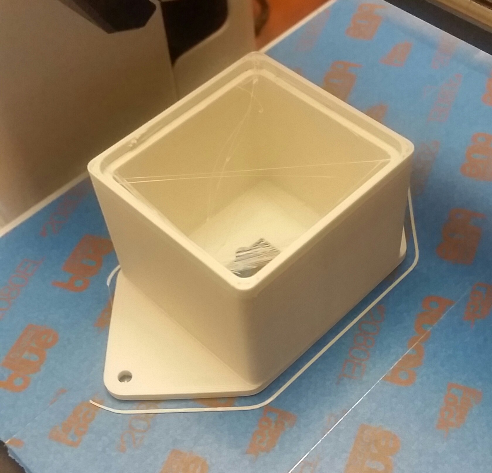
    This specific project I have decided to transition to a 3D printed enclosure after I designed and printed one up in a couple of hours and everything just worked.

    My first cut design turned out a little bigger than expected and after further investigation it doesn't look like it would work in a multi-gang outlet. I will have to remove some depth from the enclosure also since it was pretty tight in my outlet box (but no more snug if I was installing a wifi switch or any other large housing device).

  • Wiring Diagram Verified

    Eric Moyer01/21/2017 at 06:08 0 comments

    Jan 20th: I finalized my wiring a few days ago. Here is a video of the circuit in action.

    Tonight I put together a powerpoint wiring diagram to best show how everything will need to be connected. My goal is to get the circuit board from the outlet in a consumable format in Fritzing.

  • Keeping Project Costs Down

    Eric Moyer01/16/2017 at 05:57 0 comments

    Jan 15th: Project costs is something I am always trying to always reduce. Currently I have not found UL1015 wire in short lengths and only in 100' spools. Also having wires in different colors always make wiring the project easier is not a requirement. I originally spent $75 for three(3) spools of the UL1015 wire (16awg red and black, 18awg white) so that everything would be color coded and make wiring into my home wiring straight forward. In high sight I could have gotten away with just one(1) spool of 16awg and then just had to clearly label each wire.

    Another area would be to eliminate the LED switch breakout since it would get another $1-2 and just makes wiring everything up a little easier. Near term I plan to keep the breakout but it will be something I mention as being optional.

  • Project Kick Off

    Eric Moyer01/13/2017 at 06:30 0 comments

    Jan 12, 2017: The goal of this project is to use simple tools and skills to build. I don't want to limit others from building this project due to lack of a 3D printer or other expensive equipment. This will be a bit difficult since I have not found a clean cut off the shelf enclosure to house the electronics in AND still fit inside an electrical gang box. I have a great concept for a 3D printed enclosure but for the time being I will shelf that idea until I can fully develop this project.

    Along with this project please follow my daily log on Hackday.io of everything I am working on this year.

View all 6 project logs

Enjoy this project?

Share

Discussions

Rob wrote 10/05/2017 at 02:42 point

I knew there would be someone else that had the same idea i did.  Great tutorial.  I had taken apart one of the etekcity plugs to see how hard it would be and seems pretty straight forward especially now that i see this.  Any chance you could print a housing or two for me?  I don't own a printer [yet].

  Are you sure? yes | no

Eric Moyer wrote 09/12/2017 at 02:27 point

I have posted the .stl files on Thingiverse and I have added a link above.  This housing is not perfect but is 100% functional.  I would probably make the inside dimensions a little larger.

  Are you sure? yes | no

John-Paul wrote 06/22/2017 at 18:51 point

Do you have a link to the 3D Printed box? I see the link to mouser, but I was hoping to get an .STL file or similar. It seems that you modified it to have the opening for the switch.

  Are you sure? yes | no

Eric Moyer wrote 09/11/2017 at 05:39 point

Sorry I missed this request.  I will look for the .stl files and get them posted.

  Are you sure? yes | no

John-Paul wrote 09/11/2017 at 08:33 point

Awesome, thank you! Almost completely forgot I wrote about this but it would still be helpful. I have a few of them around my house now being controlled by Alexa :D

  Are you sure? yes | no

Lucas Galey wrote 05/08/2017 at 04:50 point

Very cool project! I've been using arduino and the rc.switch library to control my outlets for my own house version IoT. This is definitely a next step I'd be interested in. There a way you can share the step files for the 3D printed part? Doesn't look like a too difficult piece to make but you seem to have nailed it pretty well. Thanks,

Lucas

  Are you sure? yes | no

whitetd wrote 02/03/2017 at 06:04 point

You can normally buy usable wire from the local hardware stores by the foot, save having to buy a full roll. just make sure its good for line voltage.

  Are you sure? yes | no

Eric Moyer wrote 09/11/2017 at 05:52 point

I was only able to find THHN wire by the foot in the gauges I was looking for at the local hardware store.  I did get a few feet for early prototyping however THHN is the opposite of flexible which makes working with it a bear.  The UL 1015 that I list above is easier to work with and anytime I open up an appliance or many of the new "smart" devices they use UL 1015 (or similar).  If anyone want to pay shipping cost I would be happy to mail anyone a couple free feet of the UL 1015 I have to complete this project.

  Are you sure? yes | no

Similar Projects

Does this project spark your interest?

Become a member to follow this project and never miss any updates