 Arnov Sharma
-
1Concept-SCHEMATIC
![]()
![]()
We will use two 5V relay modules to control the AC load; to drive these relays, we used a Mosfet switch setup, which functions as a switch that can be turned ON or OFF by providing a voltage to its gate.
A 10K resistor connects the Mosfet's gate to the XIAO MCU's I/O pin.
In addition, we attached an indicator led to the I/O pin of the XIAO MCU and placed it close to each relay. The indicator LED will glow when the relay is turned on or off.
We installed an isolated SMPS to power this arrangement with AC power, which converts AC 240V into the steady 5V needed for the MCU to function.
-
2PCB Design
![]()
Subsequently, we export the netlist from the schematic and convert the entire board into a PCB file. To keep the AC and DC components apart, we first draw a square outline of the board, placing the SMPS and relay on one side and the XIAO with the remaining electronics on the other.
We later added few aesthetic markings to the PCB and sent it to Seeed Fusion for samples.
-
3Seeed Fusion PCB Service
![]()
The PCB was ordered in a blue solder mask with white silkscreen.
PCBs were received in a week, and their quality was super good considering the rate, which was also pretty low.
Seeed Fusion PCB Service offers one-stop prototyping for PCB manufacture and PCB assembly, and as a result, they produce superior-quality PCBs and fast turnkey PCBAs within 7 working days.
This XIAO HOME AUTOMATION Board's PCB quality is SUPER COOL!
Seeed Studio Fusion PCB Assembly Service takes care of the entire fabrication process, from Seeed Studio Fusion Agile manufacturing and hardware customization to parts sourcing, assembly, and testing services, so you can be sure that they are getting a quality product.
After gauging market interest and verifying a working prototype, Seeed Propagate Service can help you bring the product to market with professional guidance and a strong network of connections.
Next is the PCB assembly process.
-
4PCB Assembly
![]()
![]()
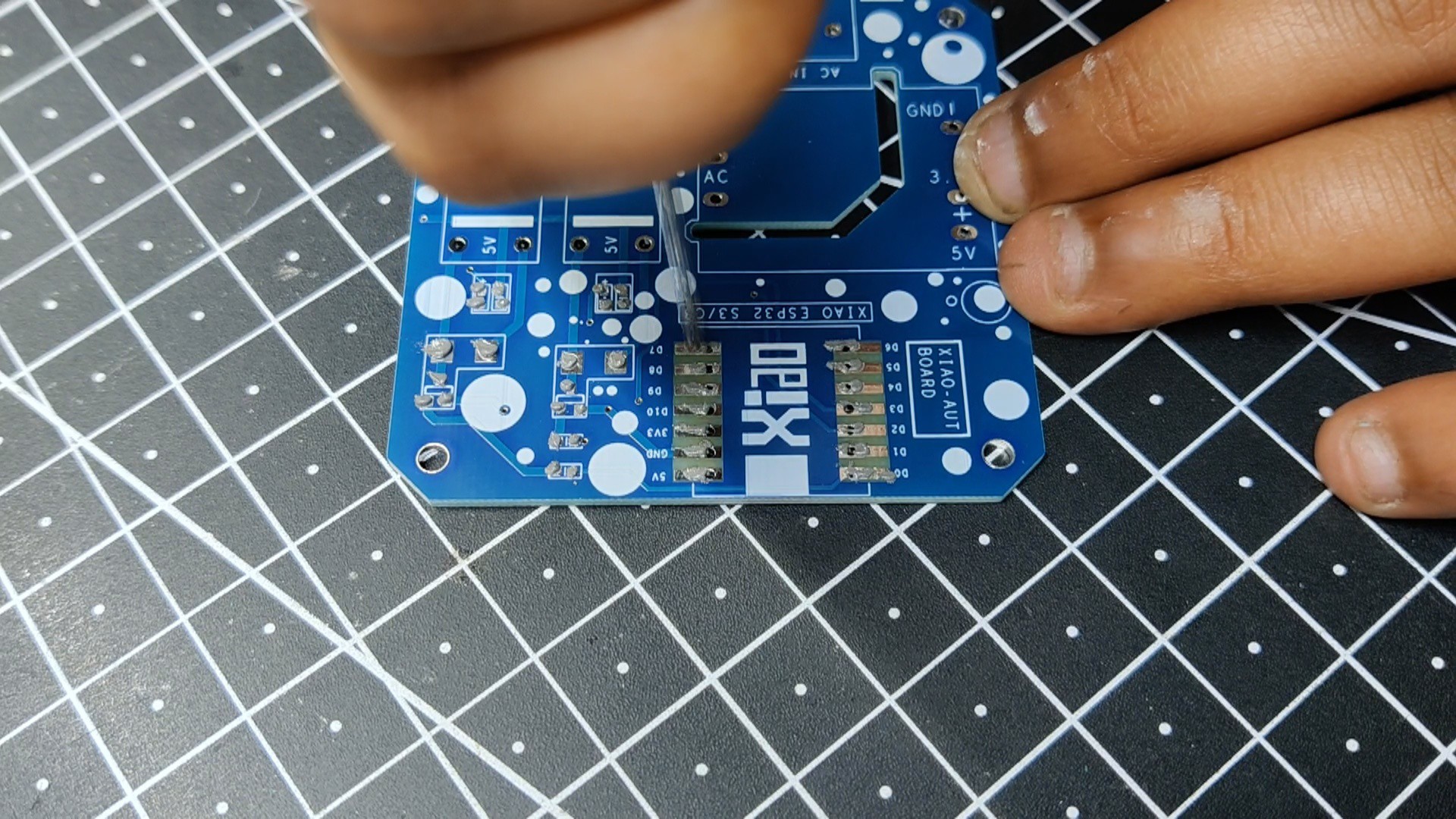
- Using a solderpaste syringe, we first add solderpaste (we are using normal SnPb 63/37 solderpaste) to the pads of each component in the PCB assembly process.
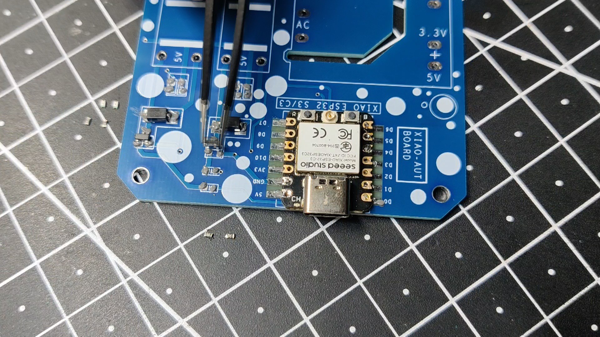
- The SMD resistors, LEDs, Mosfets, XIAO Module, and diodes are then selected and arranged in their proper locations.
-
5Hotplate Reflow
![]()
![]()
![]()
In order to heat the PCB to the solder paste melting temperature, we carefully lift the board and place it on an SMT hotplate. Solder paste melts, and components are attached to their pads as soon as the board reaches the solder paste's melting temperature.
This board is being reflowed utilizing a previously completed PCB hotplate project; for further information, see this article.
https://www.hackster.io/Arnov_Sharma_makes/pcb-hotplate-slightly-bigger-edition-6a8ed8
-
6THT components
![]()
![]()
![]()
![]()
![]()
![]()
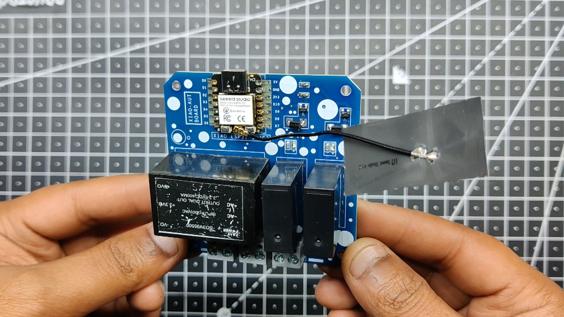
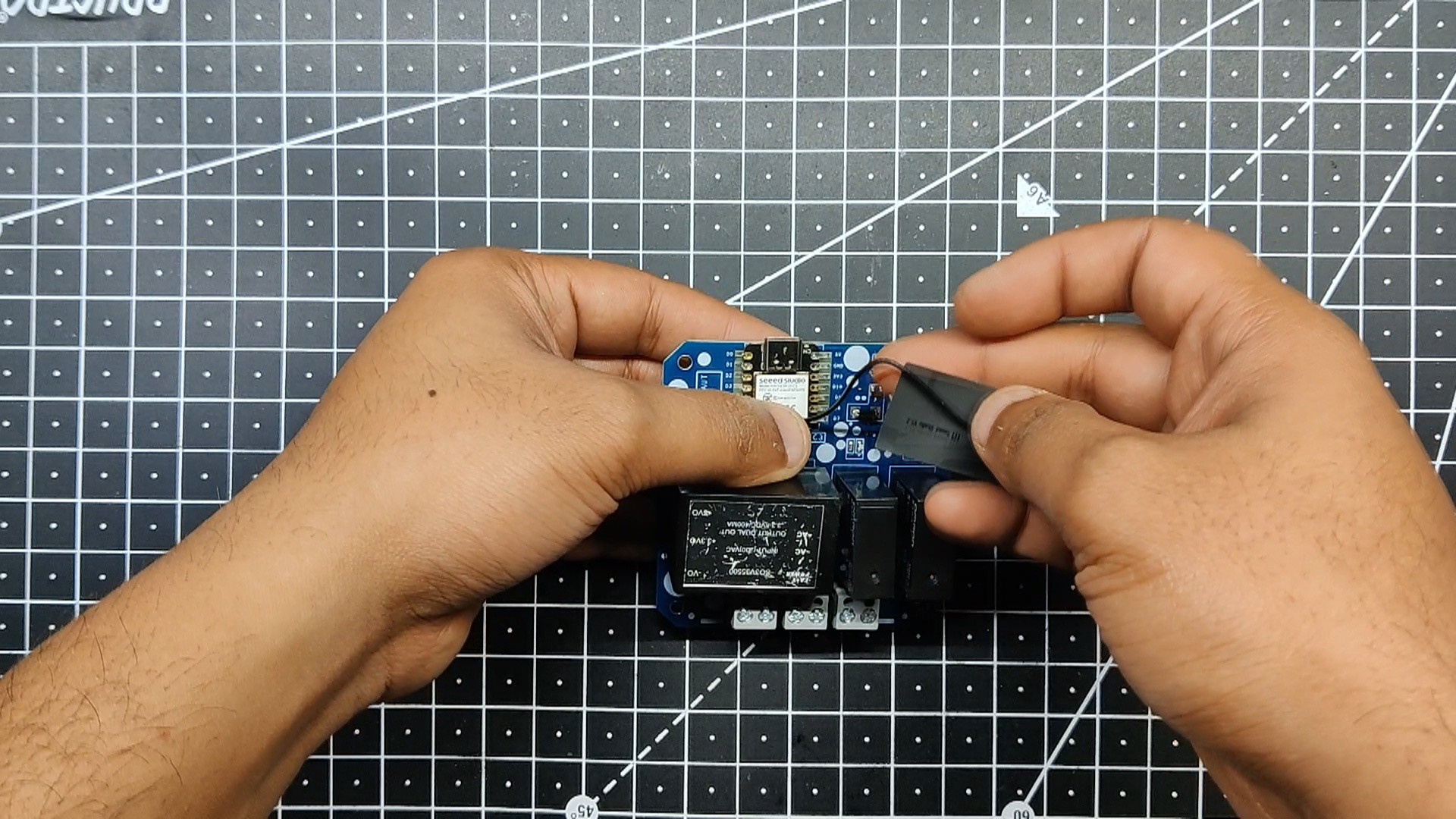
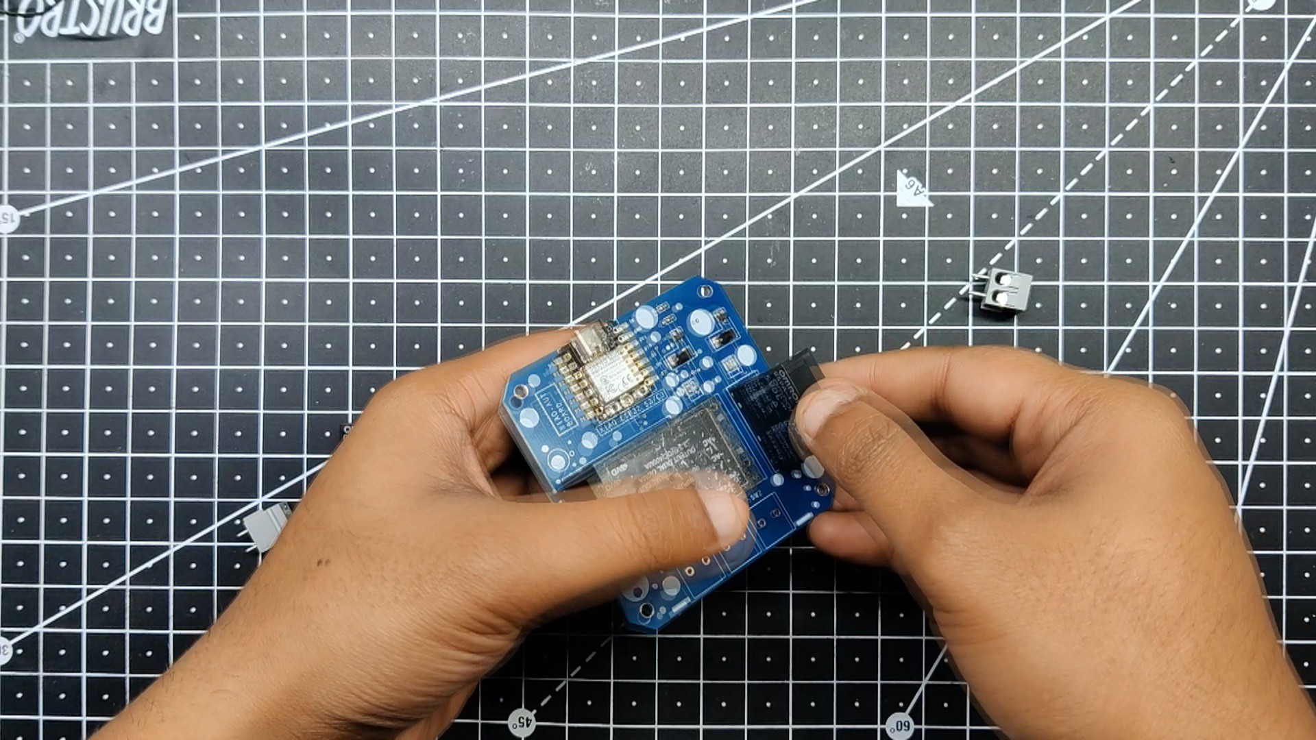
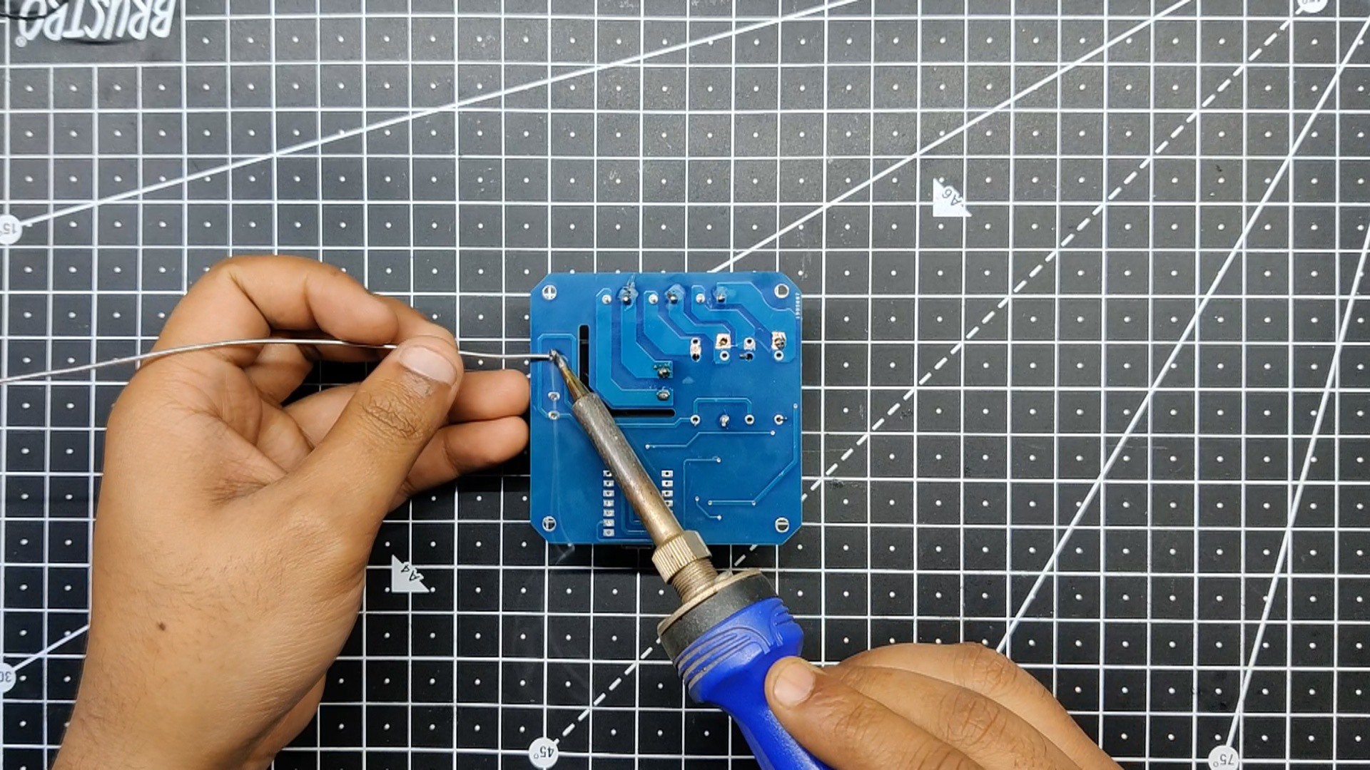
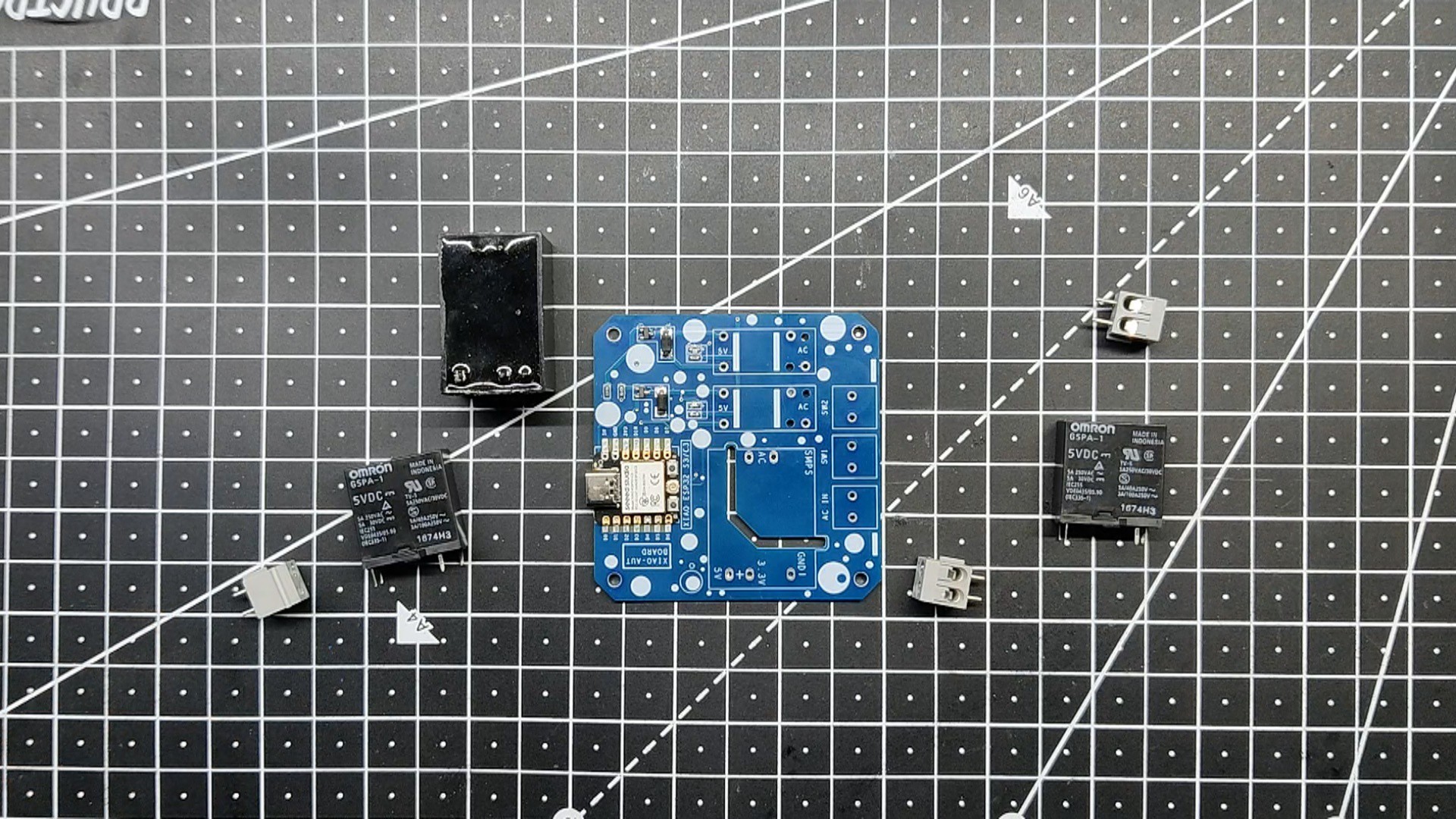
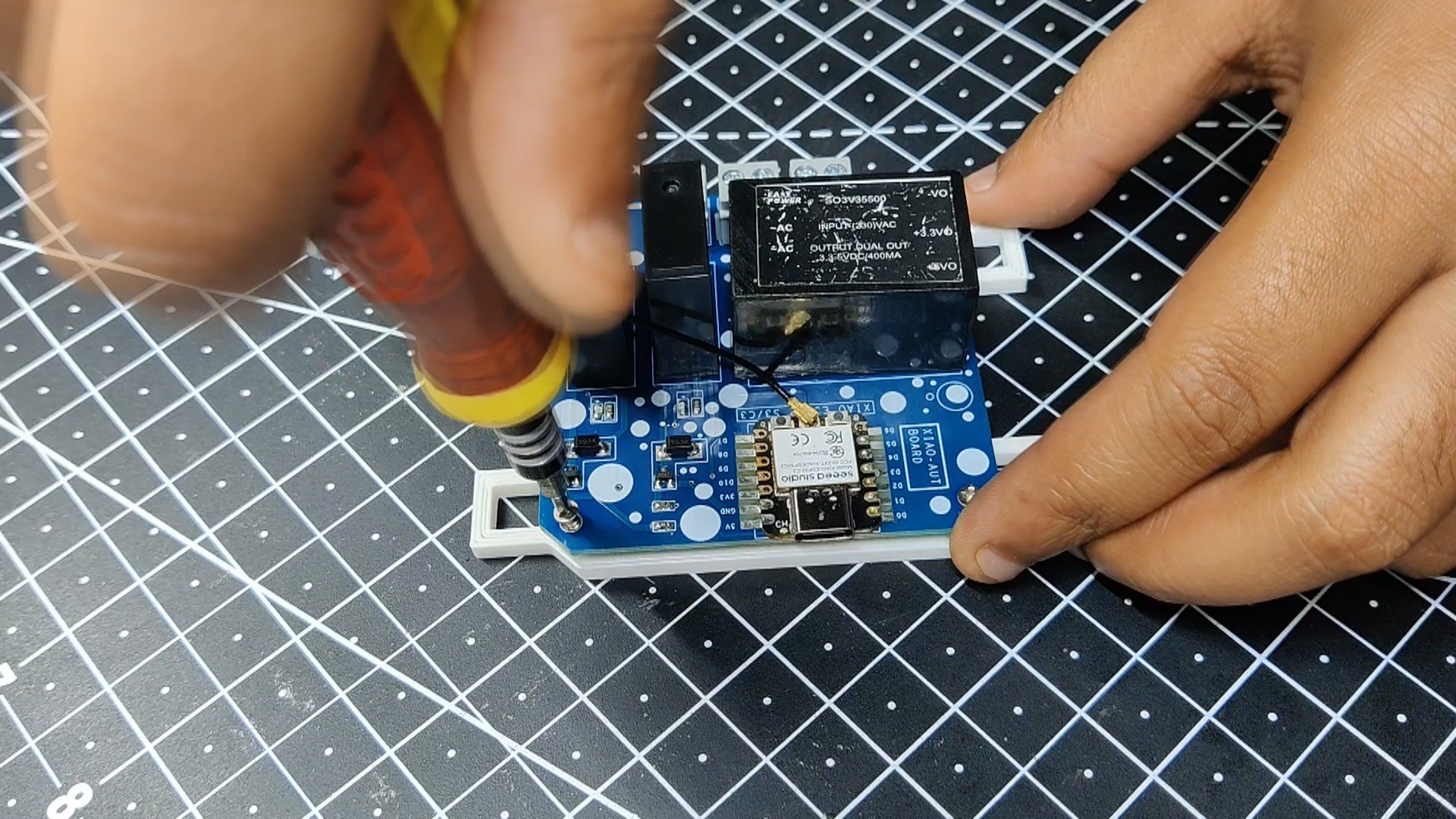
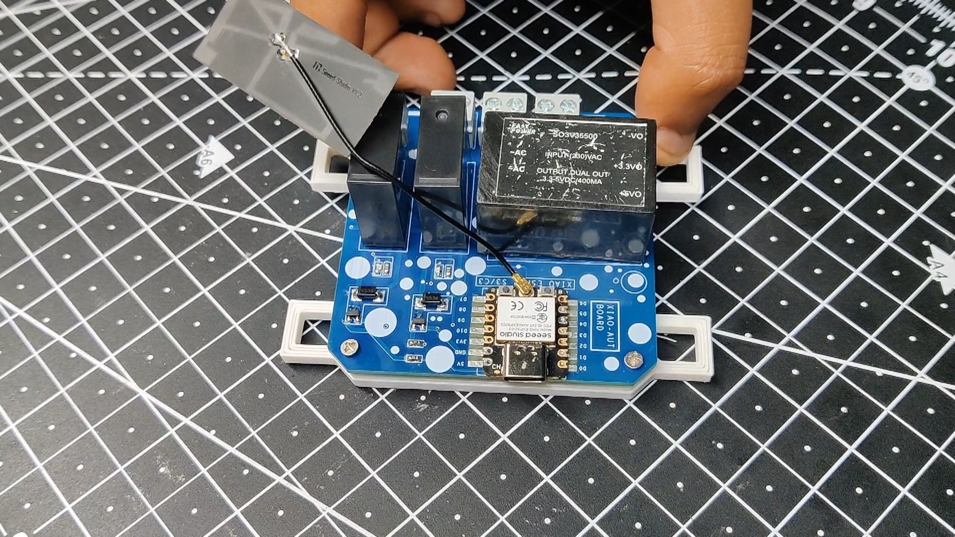
- Subsequently, we collect every THT component, comprising the relay module, screw connectors, and SMPS module.
- Using a standard soldering iron, we arrange them all in their proper places and secure them to their pads.
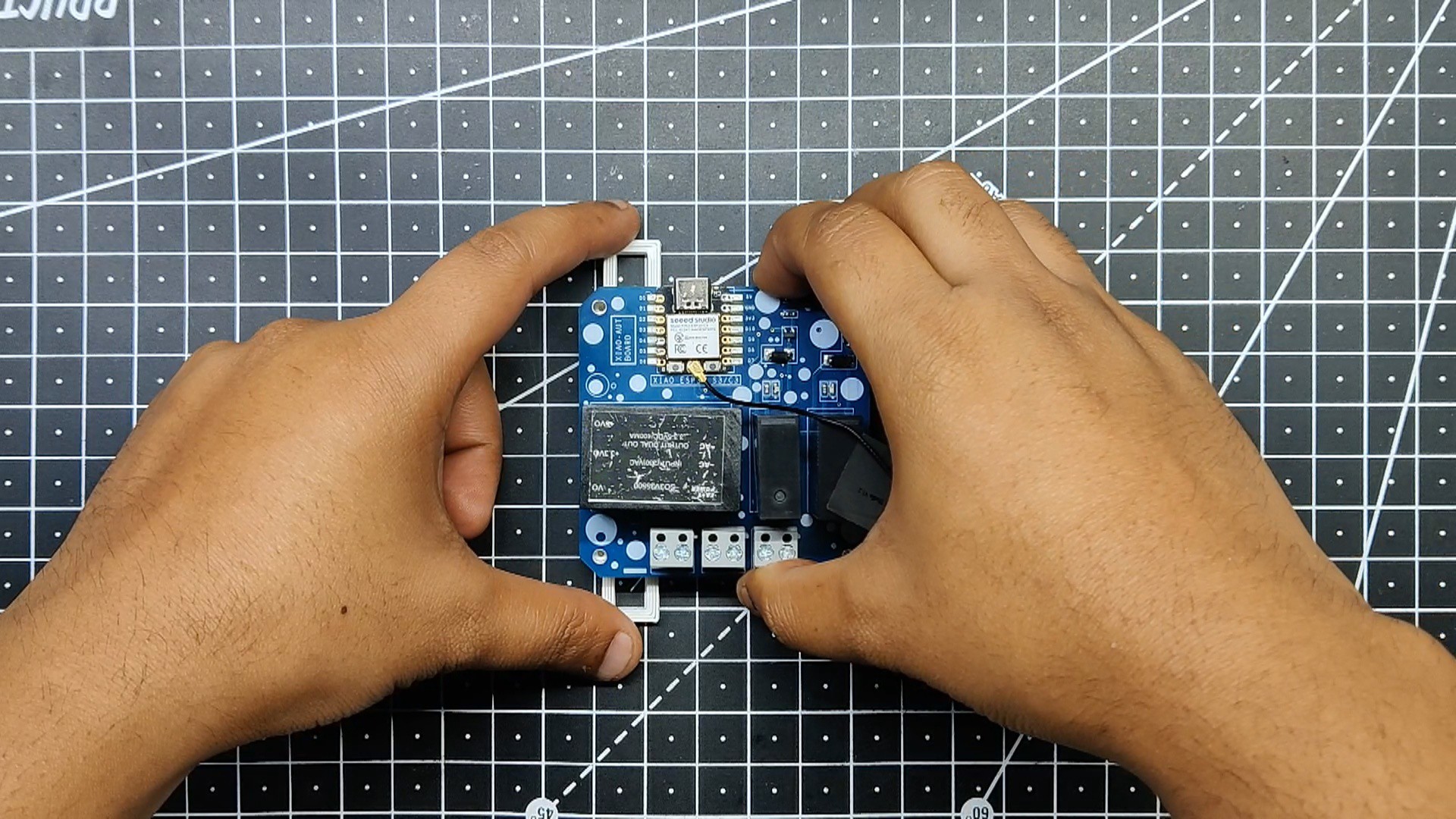
- Next, we added the WiFi antenna to XIAO's BT/WIFI antenna connector.
- The PCB has now been completed.
-
73D-Printed Stand
![]()
![]()
![]()
![]()
![]()
- This step was optional, but we designed a basic stand for the Home Automation board that elevates it slightly off the ground. It also has four mounting brackets that can be used to fasten the board to anything with screws or a cable tie.
- The stand was constructed from white PLA that was 40% infill and printed with a layer height of 0.2 mm through a 0.8 mm nozzle.
- To secure the circuit and the 3D mount together, four M2 screws were used.
-
8TEST VIDEO
Here's a test video that shows the workings of the home automation device.
-
9ADDING AC LIGHT
![]()
![]()
![]()
![]()
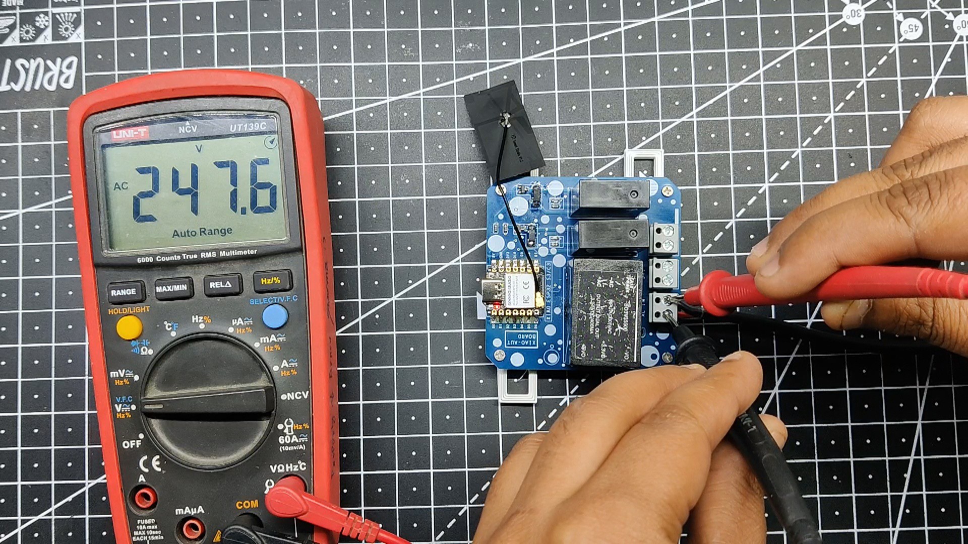
We added an AC cord to the AC terminal of the home automation device. To make sure the device is getting the proper voltage, we check the AC voltage using a multimeter.
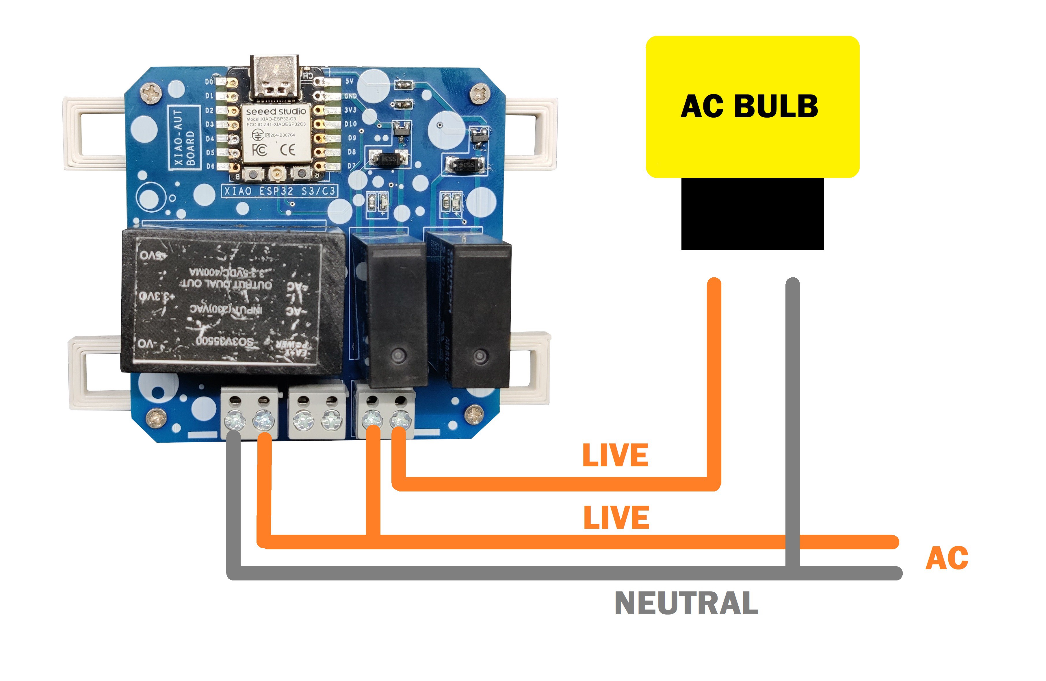
Next, we connected an AC light to the relay module's AC ter
![]()
minals and turned on the AC source by following the provided wiring schematic.
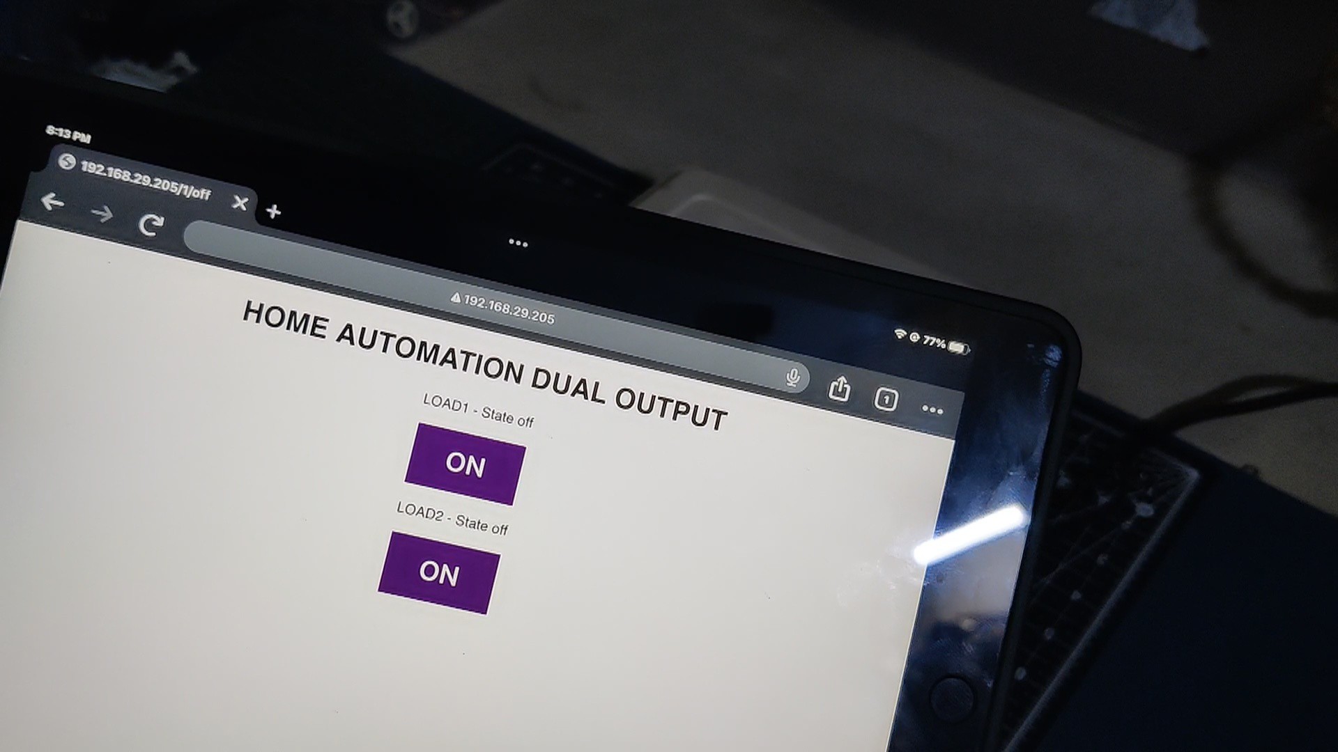
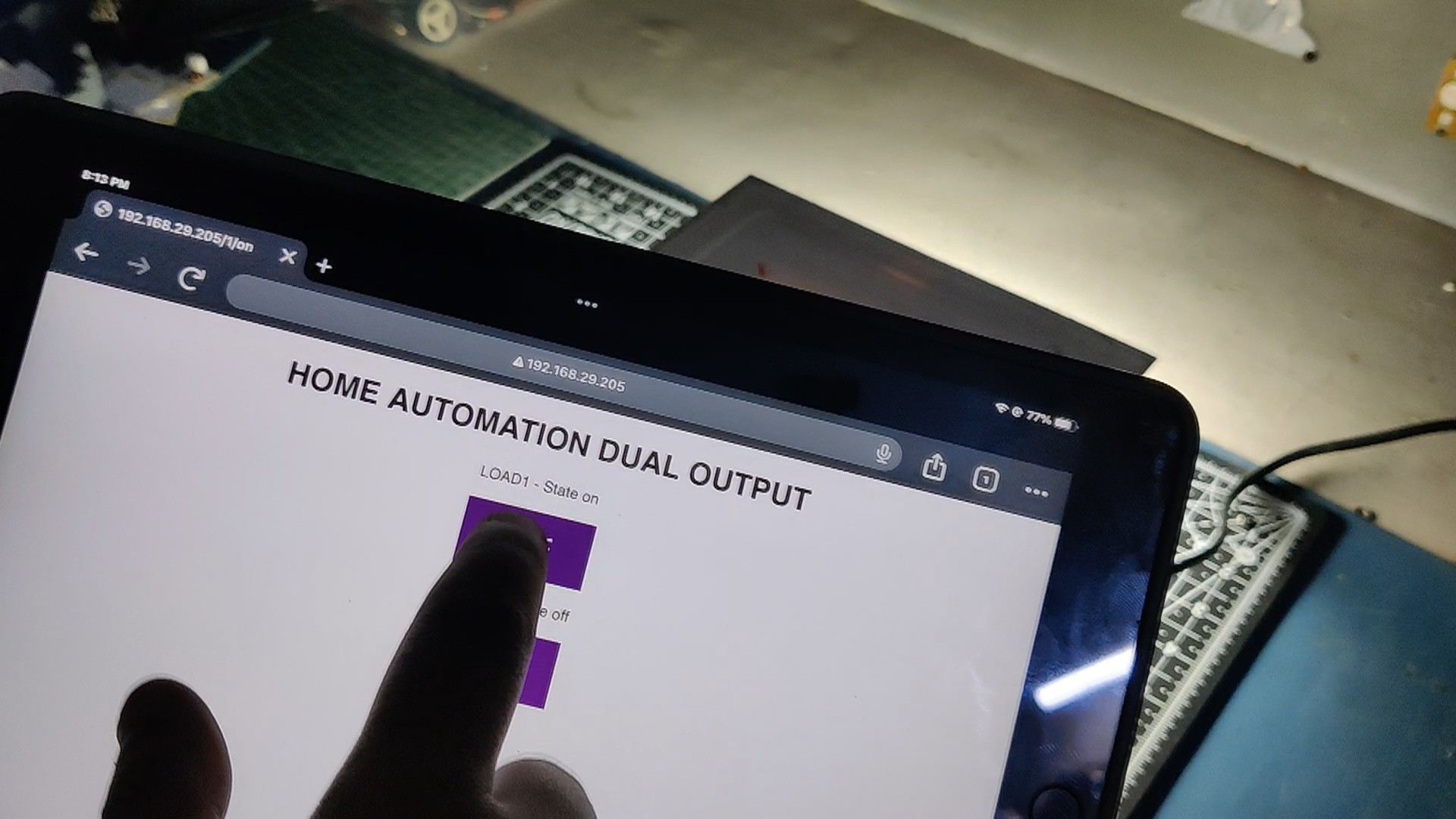
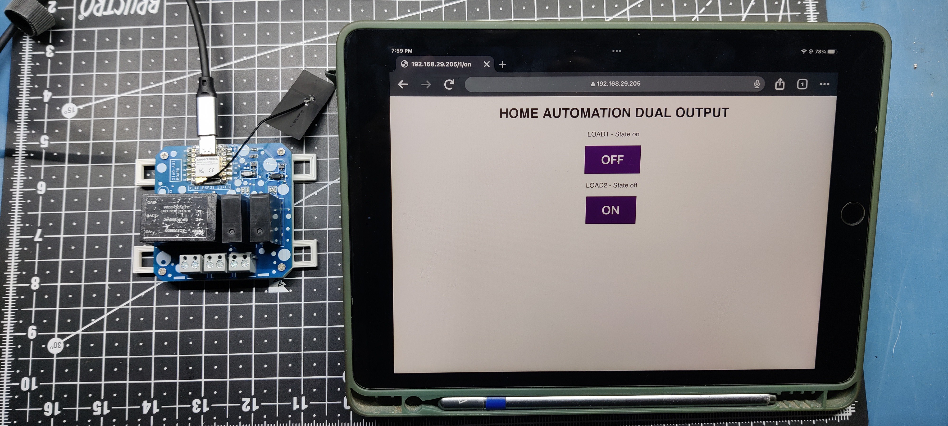
We connect through the webapp using the IP address we got from the serial monitor after uploading the sketch.
Using the web app, we are able to toggle the AC light on and off by pressing the button in the web app.
-
10CONCLUSION
![]()
This project was successful because we can use this board to turn any appliance into a smart internet of things appliance.
We can connect the relay directly to an existing power board and connect the AC switch in parallel with it to divert current through the relay and turn on the AC appliance that is connected to that switch.
Since this configuration is essentially a switch that connects to and disconnects from two ports, we can also add DC Load with relay.
By using XIAO in this project, we get super fast IEEE 802.11 b/g/n WiFi connectivity, which improves the connectivity range and makes everything run super fast.
By adding the SMPS supply to the PCB, we can easily power the whole board via AC source, which is especially helpful if we want to fit this setup outside where it is hard ti get 5V.
This project is complete, and all the files are available. Let me know if you need additional information about this project.
Thanks to Seeed Studio for supporting this project. You guys can check them out if you need great PCB and stencil service for less cost and great quality.
And I'll be back with a new project pretty soon!
XIAO ESP32 Home Automation Shield
A dual relay-based home automation device for the ESP32 XIAO C3 and S3 with an onboard power supply so it can be powered via AC 240V.


Discussions
Become a Hackaday.io Member
Create an account to leave a comment. Already have an account? Log In.