Shutter Controller use case is done. I am super happy with how well modular system behave for that. It does exactly what I want and I've already see great potential how to extend it to next usecases.
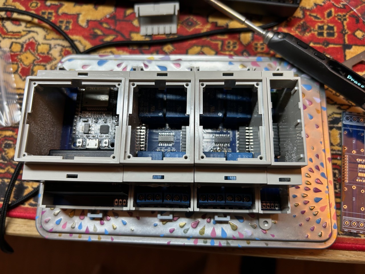
But first it was needed to put the boards in the cases that have DIN mounts. It was not super easy as some adjustment had to be done on each but final effect is satisfactory:
I had to also configure ESPHome to make all my requirements. I would not get into the details here but instead I've created repo with all the configuration:
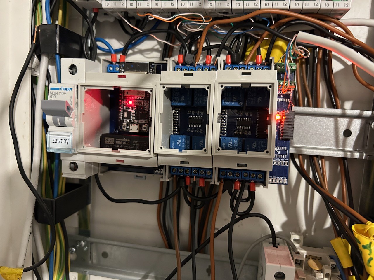
The last step was installation into the DIN rack and replacing all controller with the smart one.
What I can say, it works super great and it was fun to do that. Now I can control my shutters from buttons close to the windows as well as Hass.io. Also, I can adjust everything to my needs and customs of my family.
Already during soldering it is good to make some test. In my case it was checking if all the diodes are done correctly (it wasn't in first try). To do so I used just small power supply and jumper wires:
Some more testing can be done when fully assembled and ESPBoard is populated with the ESP32 dev kit. How to upload and run ESPHome is well describe on their webpage so feel free to check out there: https://esphome.io/
For me it is enough to be able to change the relays from ESPHome webpage to be sure that system is working and all looks good.
So not it needs to be put into the cases, mount on the DIN rail, program with some real ESPHome components and connected to homeassistant for further control.
To solder the boards there were few SMT (surface mount) components (mainly diodes and resistors) and some THT (through hole). For SMT usually you will have a stencil, pick and place machine, reflow oven to do all of that automatically but in my case for prototype all was done by hand.
I've put some solder paste onto the board with solder paste dispenser and reflow it using the hot air. Doing so requires some patient as you cannot add to much of the blow or temperature as you might move the components out of the pads. Exact positioning is not required as solder will move it and position nicely when it is hot.
For the first time it can take longer but already on the second board it is just around one minute.
On this board passive components and diodes are only 0603 imperial so it is 1.6mm x 0.8mm. Going as small as that does not introduce any major difficulty.
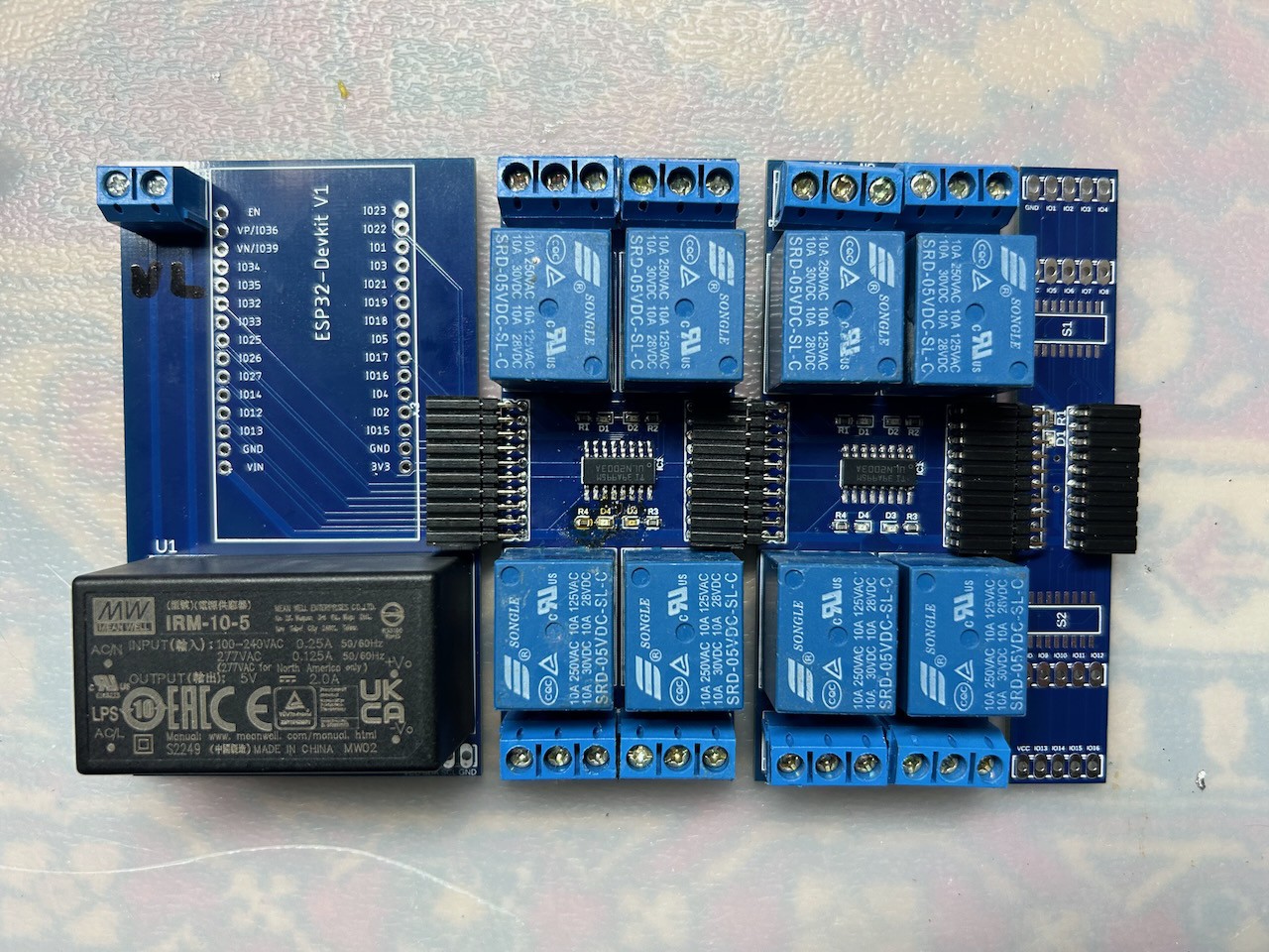
Soldering is a rewarding process and after maybe an hour boards are fully assembled:
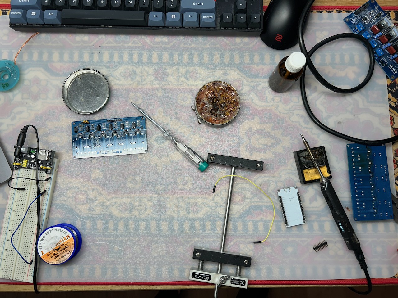
And one of my favourite view on the bench after the work:
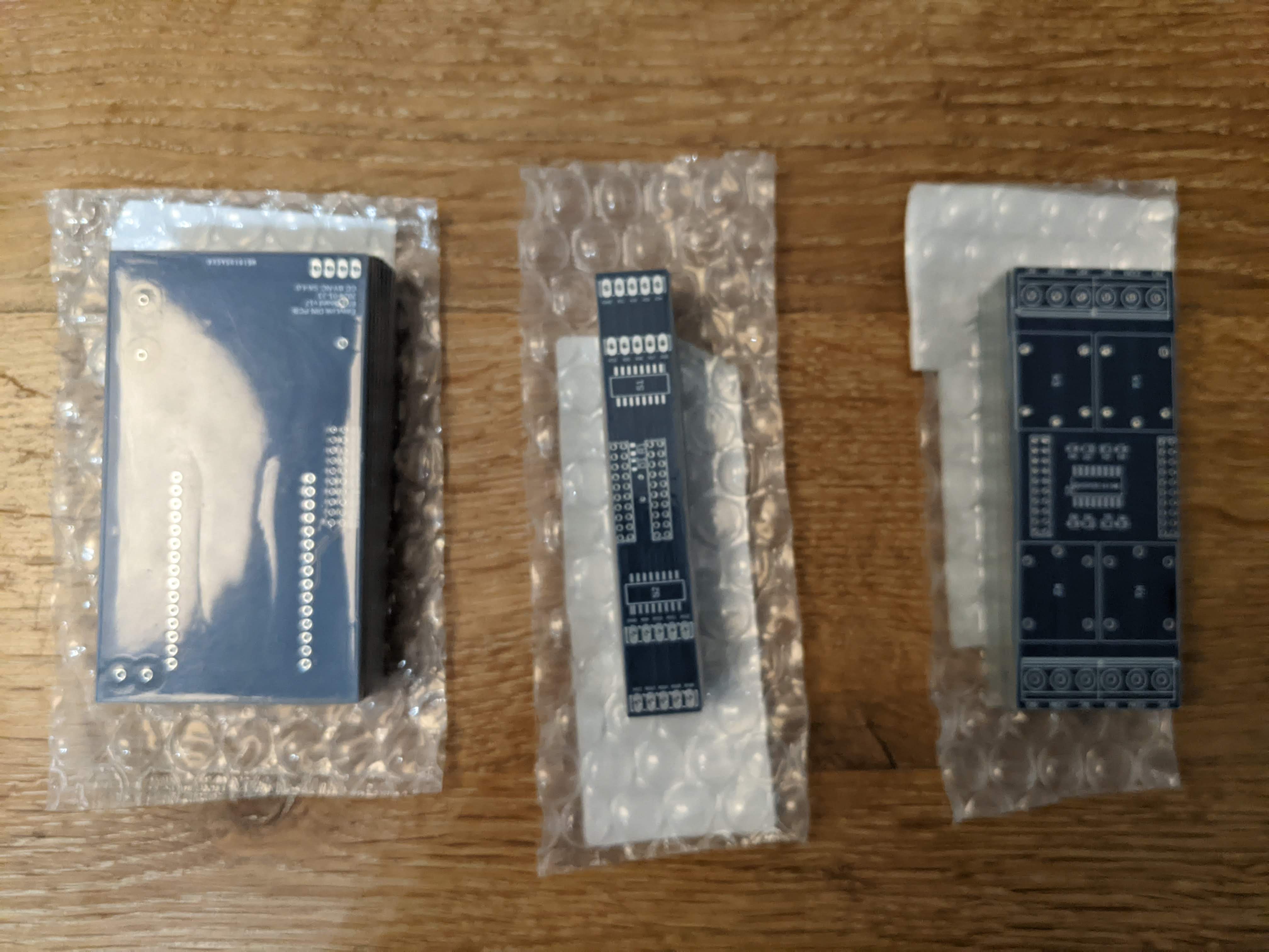
I am exited to share that PCB for first three modules are right now under production by PCBWay.
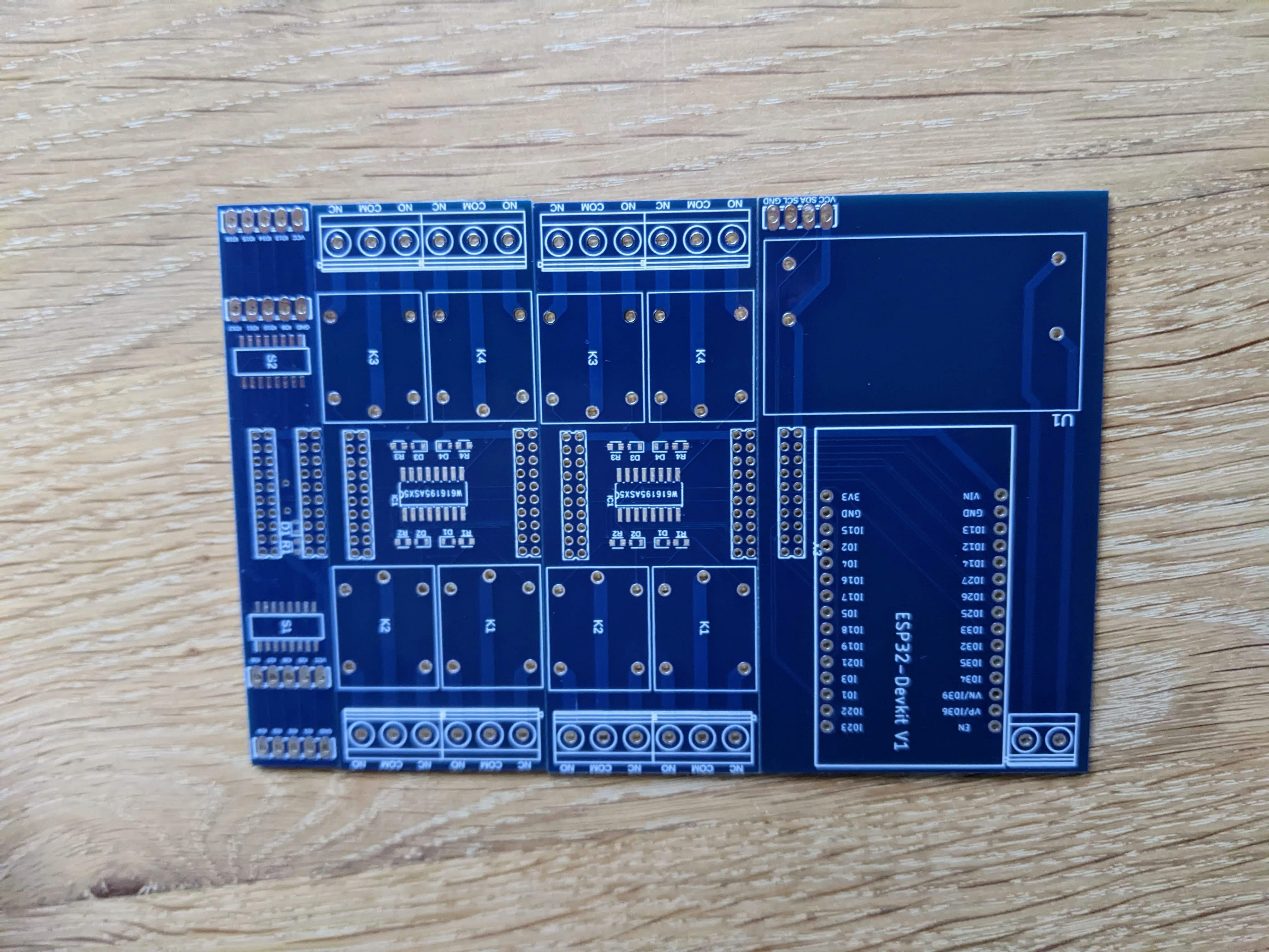
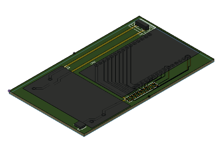
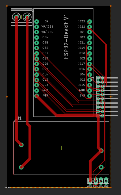
ESP Board
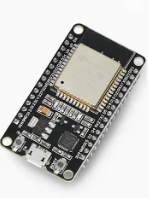
First module is simple ESP32 board that can take 32 pind ESPDevboard like that:
and expose 16 GPIO pins as well as I2C line through EasyLink system to rest of the modules. As mounted flat this board already takes some space also integrated 230V/ 5V power supply can be soldered and used so there is no need for any external power supply.
However this board also provide an option of screwing VCC and GND from any external source as well as I2C line if it is needed.
Board suppose to build very simple as complexity of handling of ESP32 lays inside devboard already.
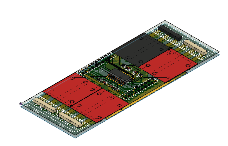
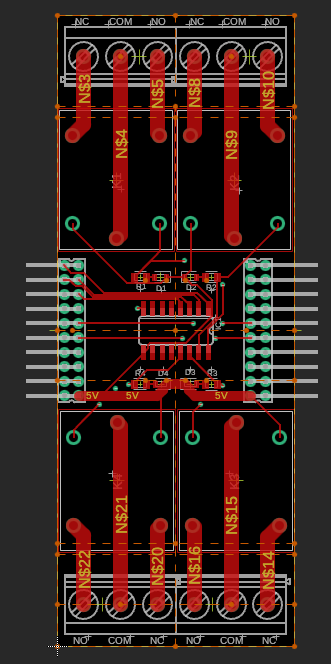
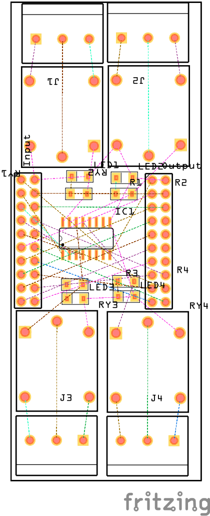
4ch Relay
This module I have spend the most time on. FIrst it is the most complex one and involve handling significant amount of current as well as high voltage area.
PCB traces of relay main voltage are designed to handle 10A of current with temperature rise of 25C over the ambient temperature with only 1oz thickness. This is theory that you can get from many calculators like that: https://www.pcbway.com/pcb_prototype/trace-width-calculator.html. That is also something that I am quite interested to check with thermal camera on my prototype. Anyways if you are handling main voltage please be very careful as there is many considerations on the way and I am not an expert in this area whatsoever.
This modules takes EasyLink connection and uses first four GPIO pins shifting remains 12 on output side for other modules. That means that single ESP Board can drive 4 such modules connected in series or 2 such modules and still 8 GPIO remains for other modules. I am thinking about some I2C GPIO pin extension module to break it limit but first let's confirm base modules working.
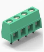
Terminal Block
Last module is just screw terminal block connector compatible with our EasyLink system.
Thanks to mounting 4 blocks with 5 position each I am able to securely attach 16 general input/output pins and on remains four position that is 2 time GND and 2 time VCC. In this way I hope to deliver secure and reliable connection to switches and buttons that are external to our line.
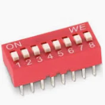
As this module can be mounted in any position of our EasyLink line each GPIO has a switch to detach it from passing it to the following module. It is realised by DIP switch that can be turned on and off.
PCB is design to fit into standard 1M size DIN mounted case.
Once again thank you PCBWay for sponsoring first production and looking forward to soldering.
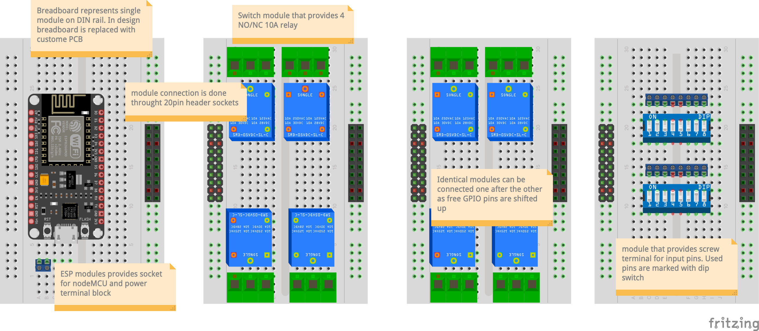
System is design in modular way. Each module is mounted on DIN rail and connected one to the other with terminal block. First module contains ESP32 which is "CPU" of the whole block. Each next module is consuming GPIO from previous and shifting "free" pins back to the top. In this way identical modules can connect one to the other and use free pins.
Basic system is presented at this diagram:
Terminal block specification:
1: GND
2-17: GPIO
18: SDA (I2C)
19: SCL (I2C)
20: VCC
In this way 16 GPIO are provided between modules as well as I2C line that can be used to extend system with additional GPIO or advanced functionality (voltage, current, power, etc.).
Switch module consist of 4 10A relay blocks and fit into 2M (18mm*2) space. Four GPIO pins are consumed by each module leaving N-4 pins, where N is the number of initial pins to the next modules.
This module provide a possibility to control 4 230V inputs. As each relay has open and close channel it allows also to control curtain motors which cannot get both mains simultaneously. This can be realised by connecting zero output to input of the second relay.
 Marek
Marek