(Project description is a work in progress)
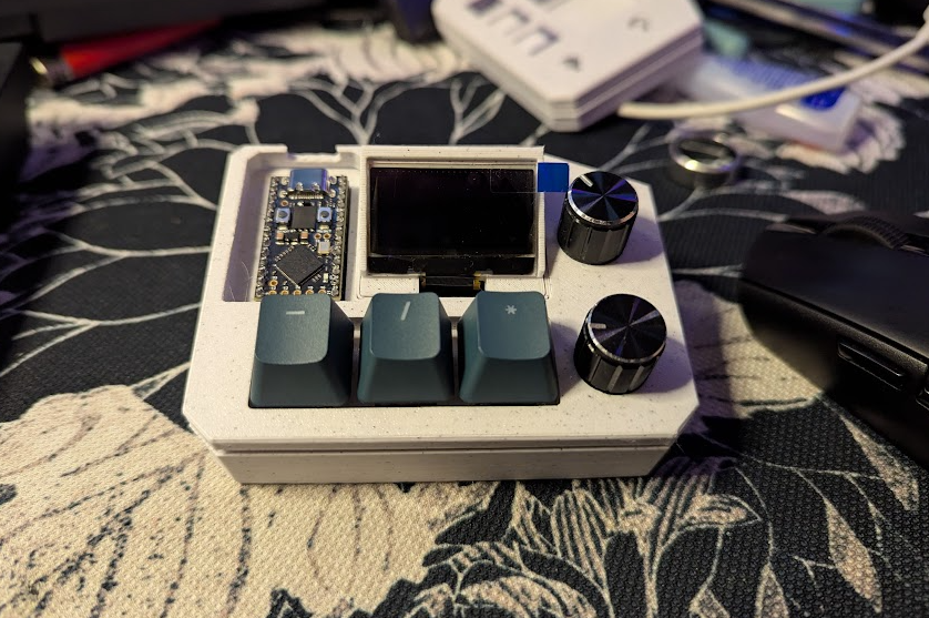
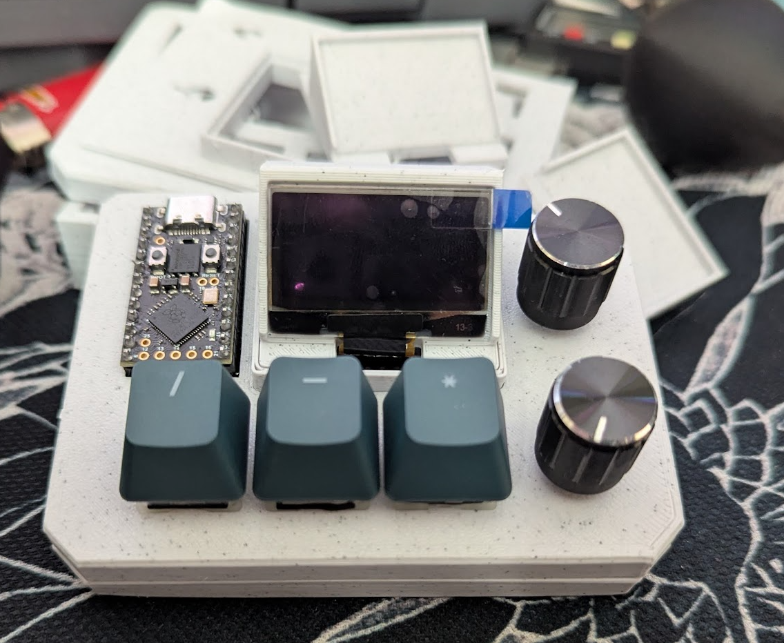
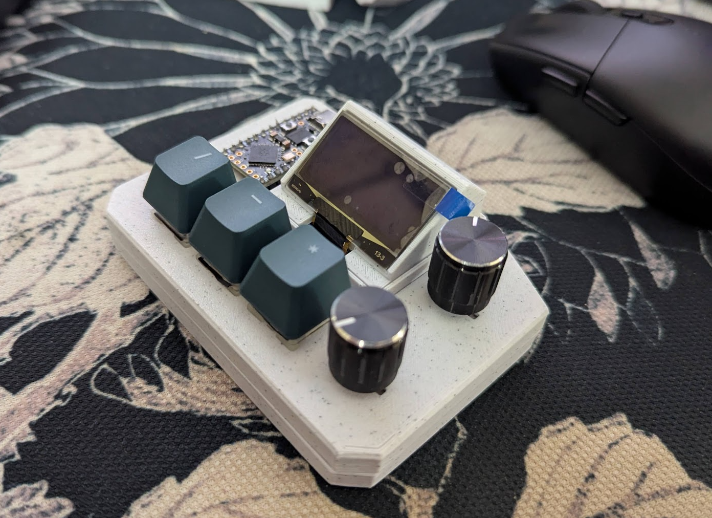
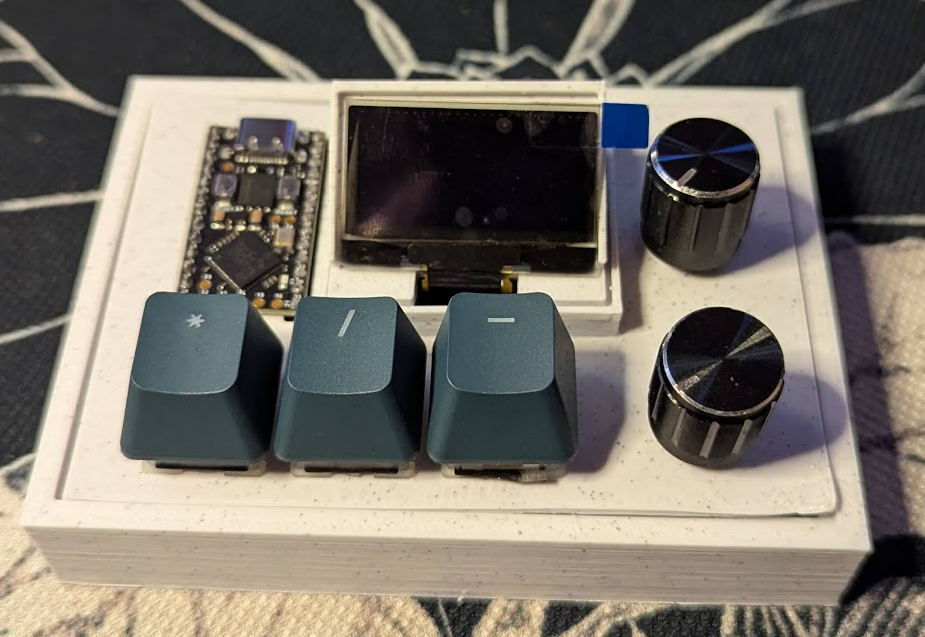
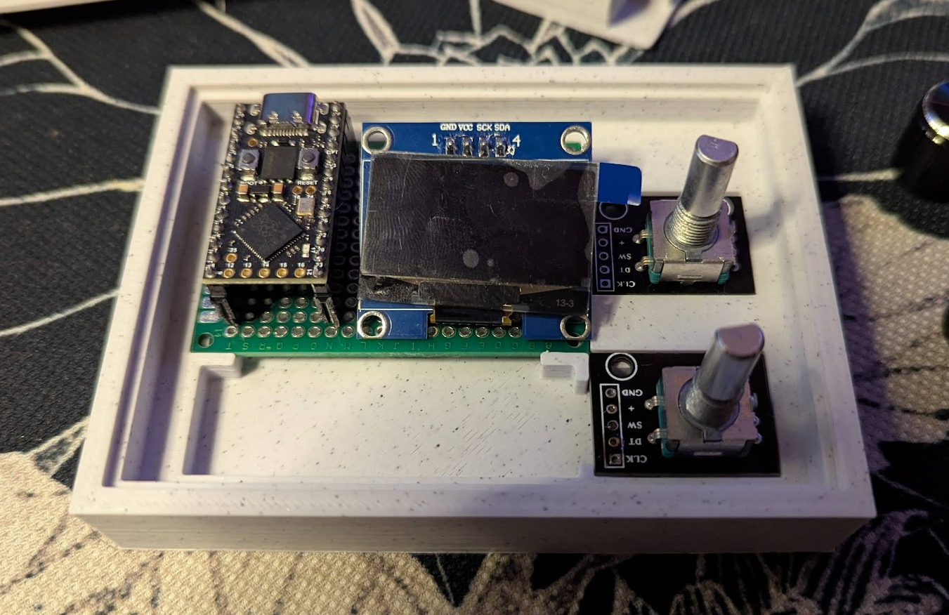
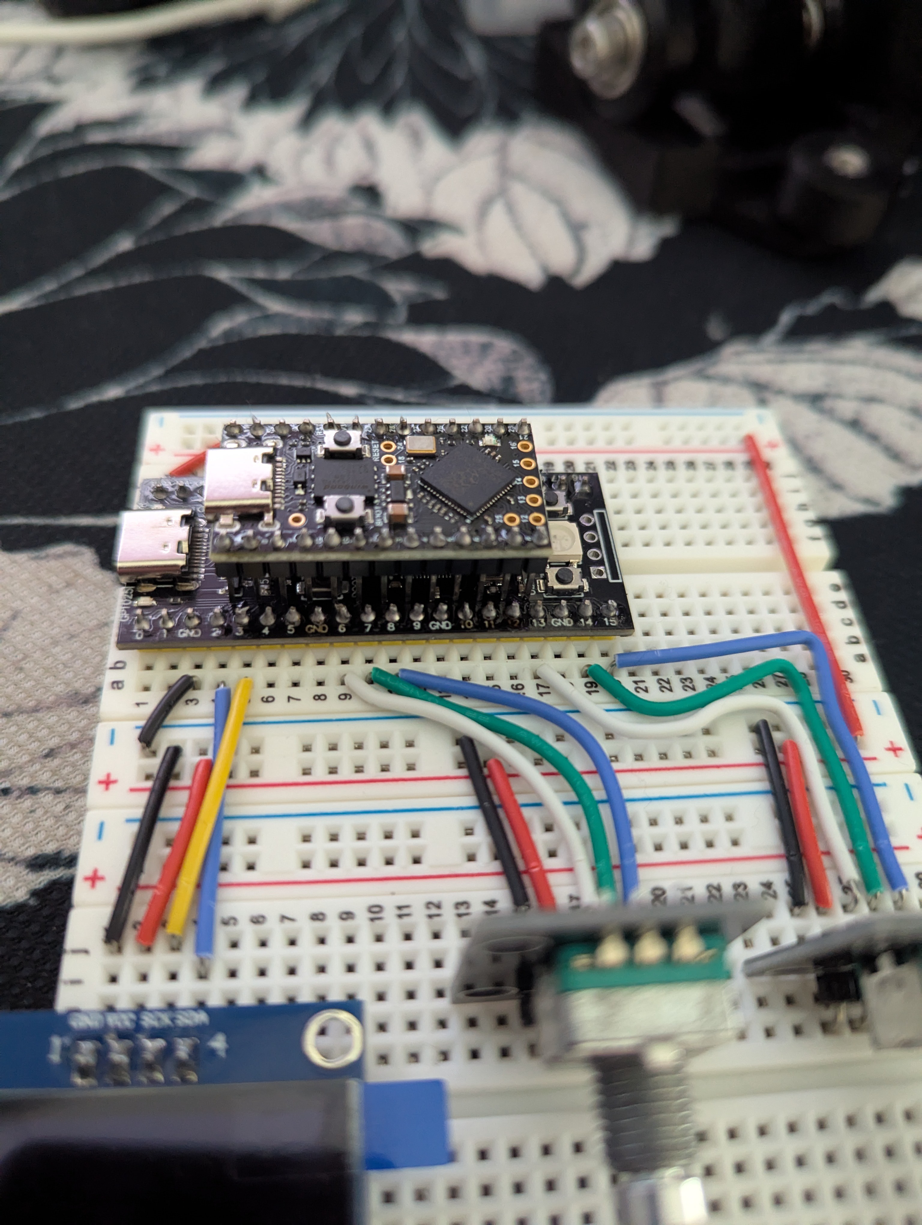
A DIY USB Volume controller and macro pad, powered by an RP2040.
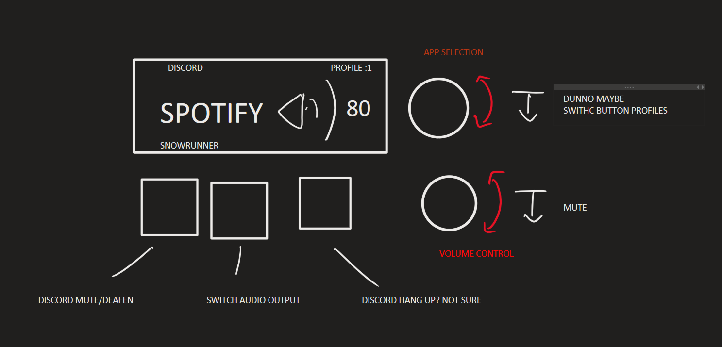
Per-application volume control with the current profiles/applications in mind:
- Master volume
- Current window
- Spotify
- Discord
- Web browser
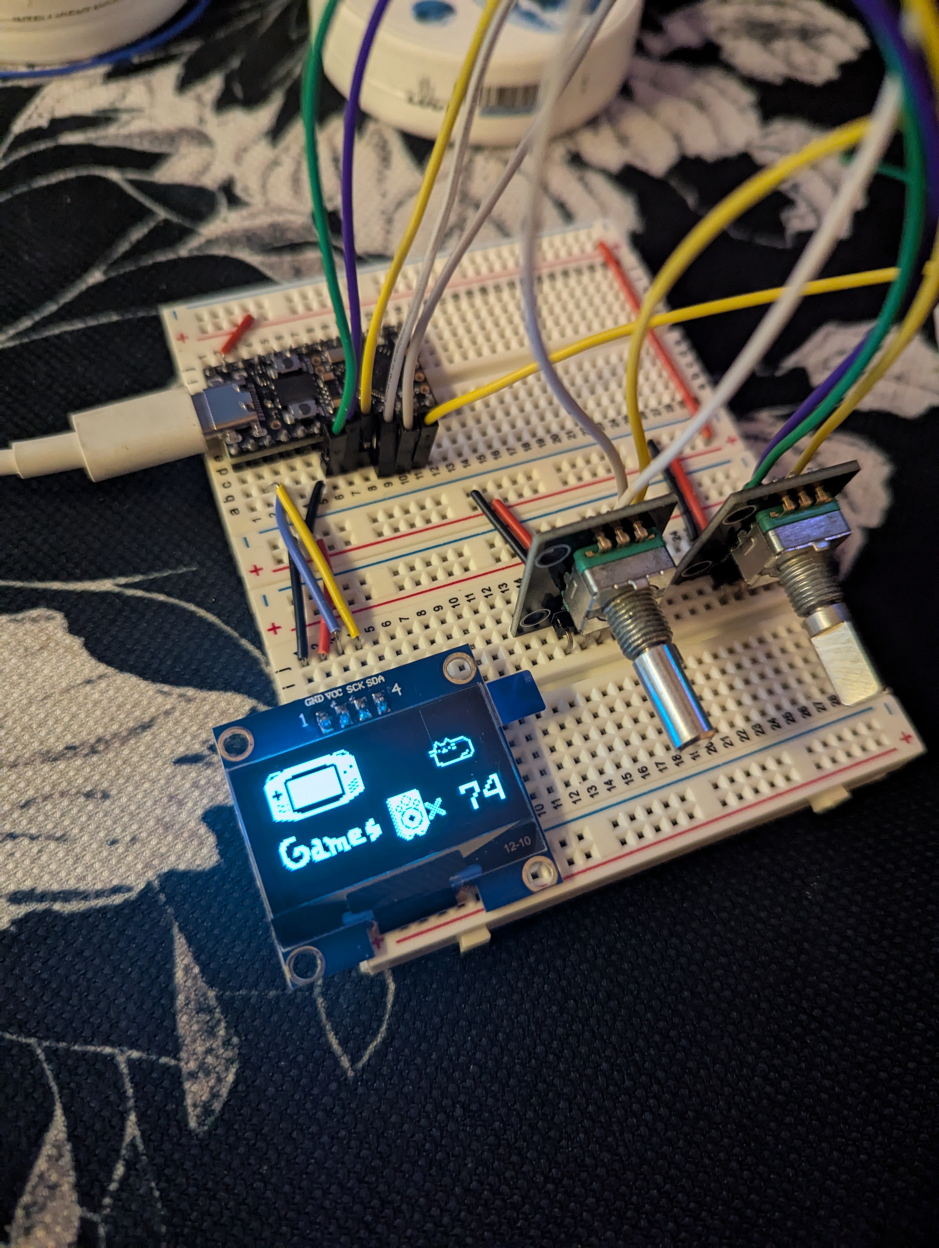
- Video games
Game application names must be added in config file
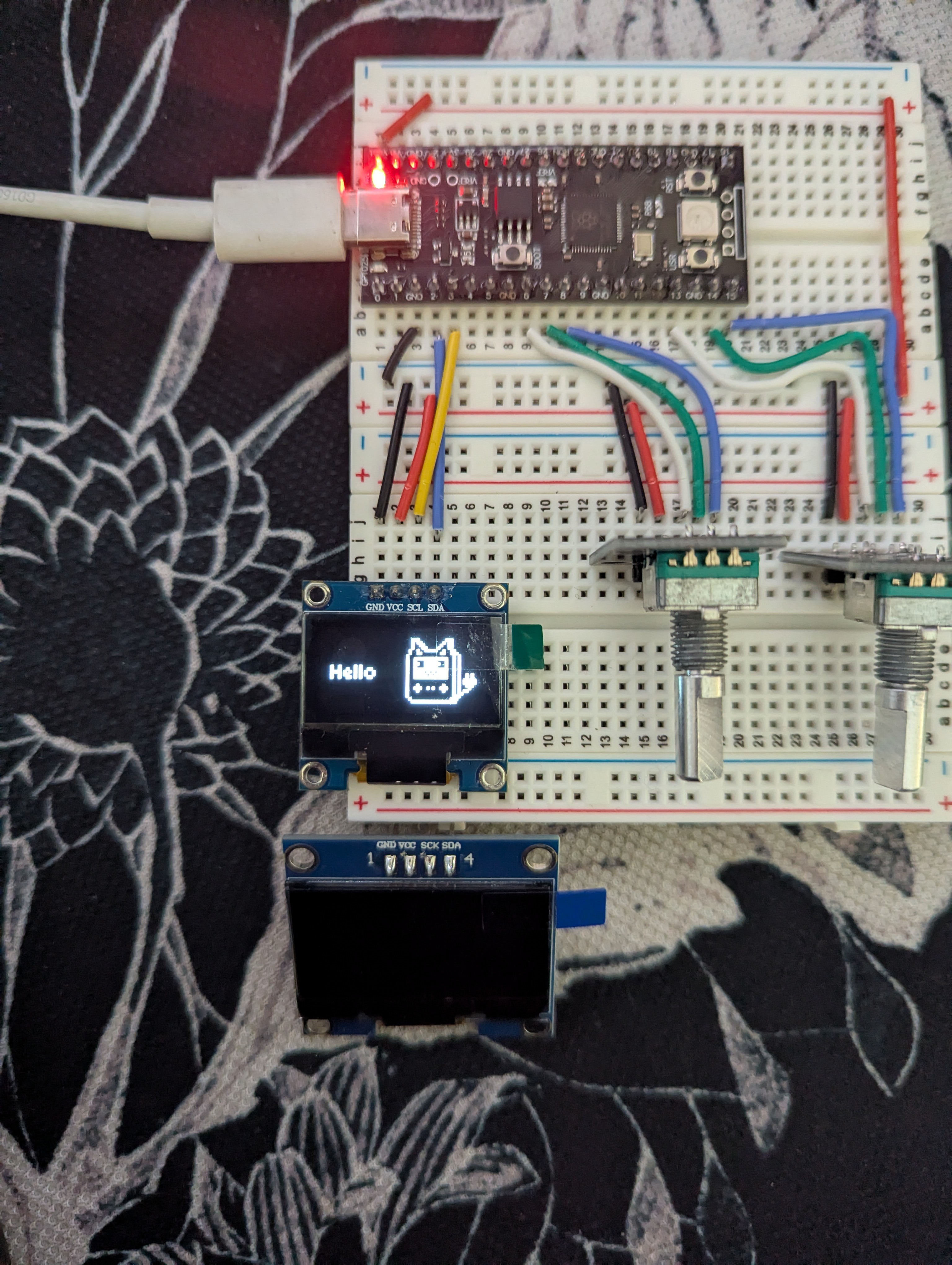
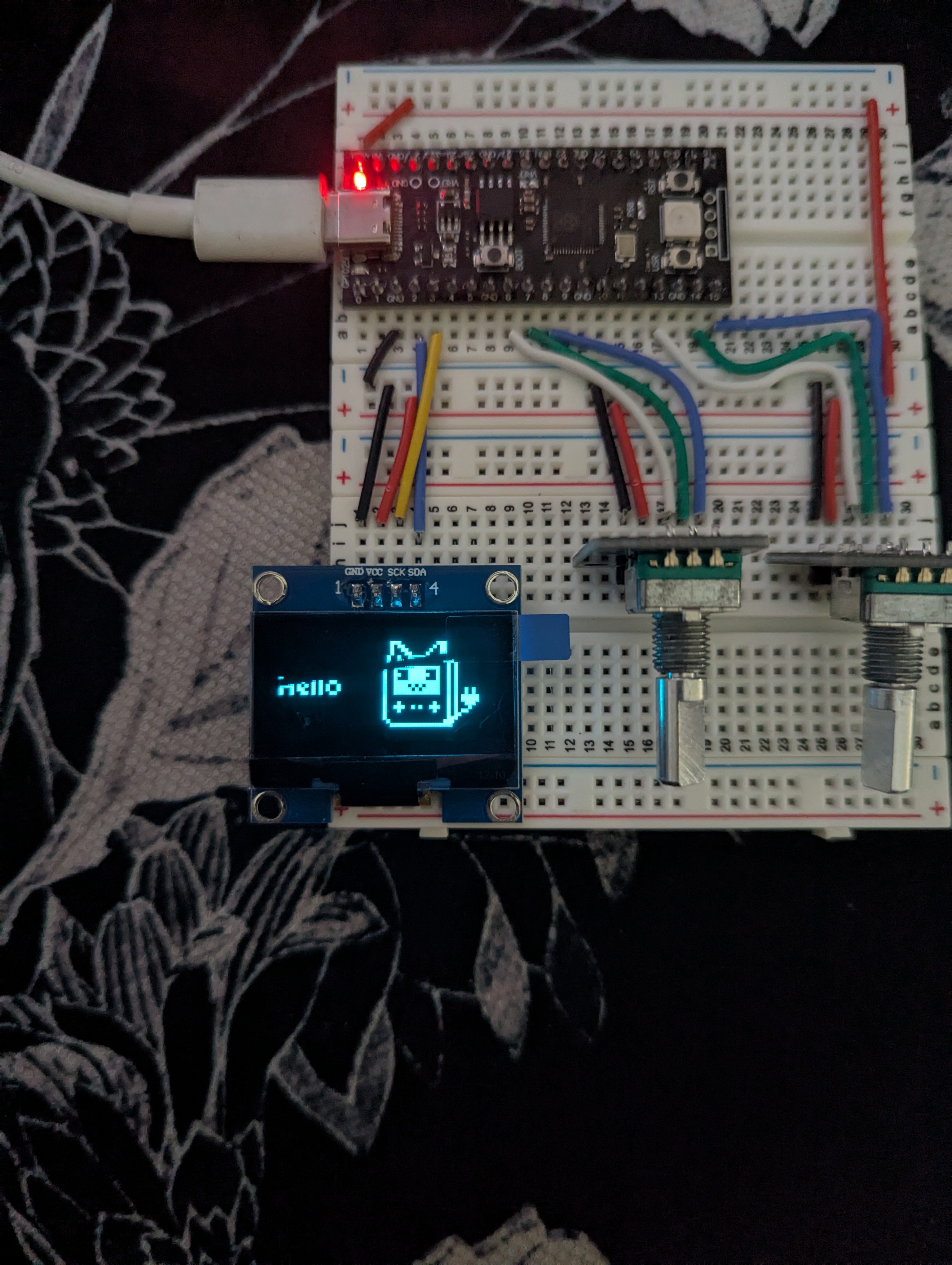
OLED display for monitoring current volume and currently selected profile
This project is inspired by the Maxmix (https://maxmixproject.com/) and deej (https://github.com/omriharel/deej).


 WJCarpenter
 Christoph
 Albert Gonzalez
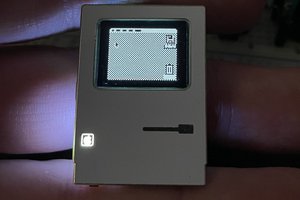
 Aaron
Aaron