jaromir.sukuba
-
Project B
09/24/2017 at 08:25 • 0 commentsWhile drawing first sketches of my overgrown calculator computer, it was clear I will not finish here. I thought of having something slightly bigger, with better display and full-blown QWERTY keyboard. As it still belongs to RPi zero handheld computer, I decided to call this project B, while first one is project A.
I think the biggest limitation of project A is its display - while being small and relatively low power, 320x240 will not cut it for many GUI applications. I took a look around and it's not easy to find SPI displays of higher resolution and I'm not surprised by this. The amount of data required to refresh such as amount of pixels would be outside the reach of SPI transfer; leading to either high SPI clocks, or slow refresh. Most of displays with higher pixel resolution are having parallel interface; the cheaper ones without any controller. This is called DPI interface and the LCD is designed to be fed with constant stream of data, just like scanned television or VGA monitors, with both horizontal and vertical synchronization pulses. Fortunately RPi do contain DPI controller and it can be enabled and used.
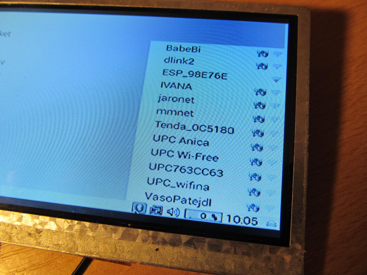
The better part of display being "dumb" is that displays are mostly interchangeable and one is not limited in choice of particular controller. They have even mostly the same connector with the same pinout. I opted for 5" 800x480 LCD module from tme.eu and made simple breakout board for it, taking inspiration from TFT friend by adafruit. It contains nothing but step-up converter for backlight and single resistor in series with pixel clock line, to decrease slew rate and possible ringing on this fast and long PCB trace. After a bit of playing with overlays and config.txt in /boot directory I got it working relatively painlessly and the result is great. In fact, it looks crispier in reality compared to relatively dull colors on photographs.
![]()
![]()
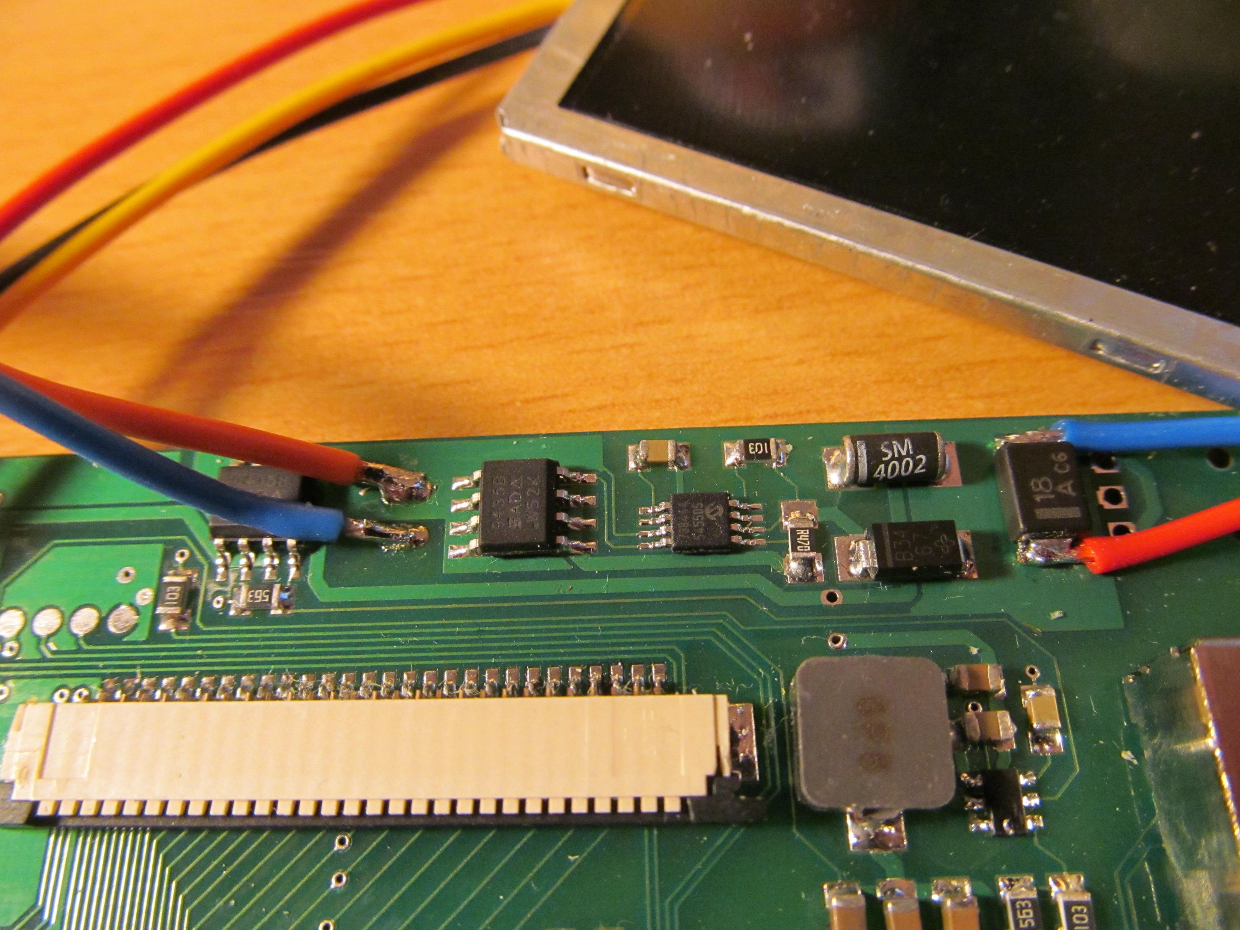
![]() There is really nothing but single resistor on bottom side
There is really nothing but single resistor on bottom sideNo
![]() The whole setup takes approximately 1,5 Watts during run. It could be lower, but this is still manageable
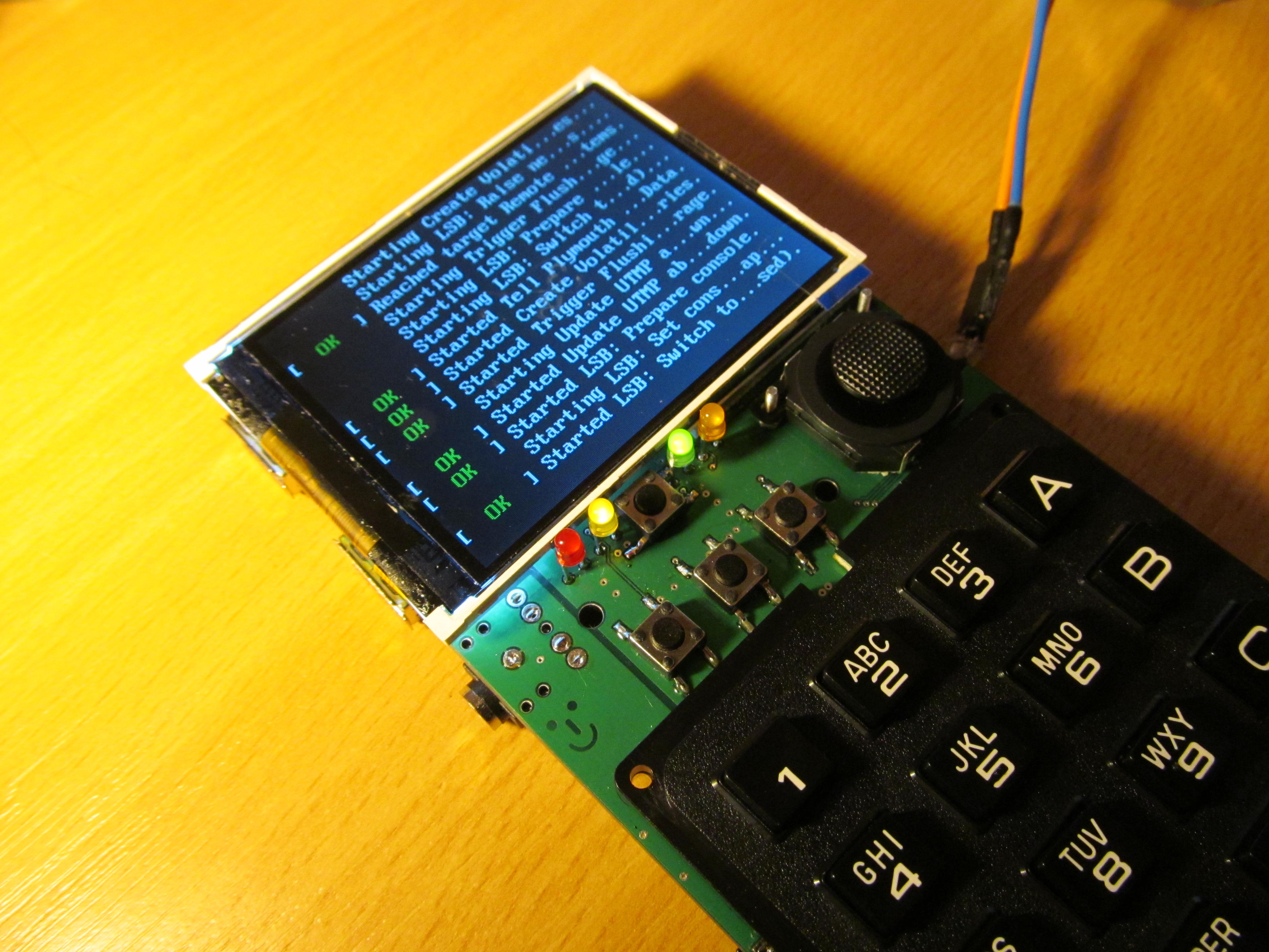
The whole setup takes approximately 1,5 Watts during run. It could be lower, but this is still manageable![]() Now I'm in the process of adding keyboard and pointing device to this - not the joystick I had on project A, but touchpad. This is going to be non trivial process, as most of the GPIO pins are taken by DPI interface and this time I don't want to run everything from internal USB. Stay tuned.
Now I'm in the process of adding keyboard and pointing device to this - not the joystick I had on project A, but touchpad. This is going to be non trivial process, as most of the GPIO pins are taken by DPI interface and this time I don't want to run everything from internal USB. Stay tuned. -
Howto, github update
07/25/2017 at 08:16 • 0 commentsI updated my github repository and added some comments to readme file
Notice also https://github.com/jaromir-sukuba/pi_zero_computer/blob/master/other/howto file describing steps to make the device running from vanilla Raspbian Image.
I also uploaded design files here on hackaday, in single big package. BOM and schematics are also separately, for easy viewing of those files.
-
Modus operandi
07/24/2017 at 11:59 • 0 commentsAs I wrote in FAQ - if you need to ask what is this project for, you probably don't need it. I build it for my own enjoyment during design and build, as well as machine to allow me to better learn programming/scripting languages (and to listen to my favorite tunes while doing so) and as ultimate nerd status symbol to carry around.
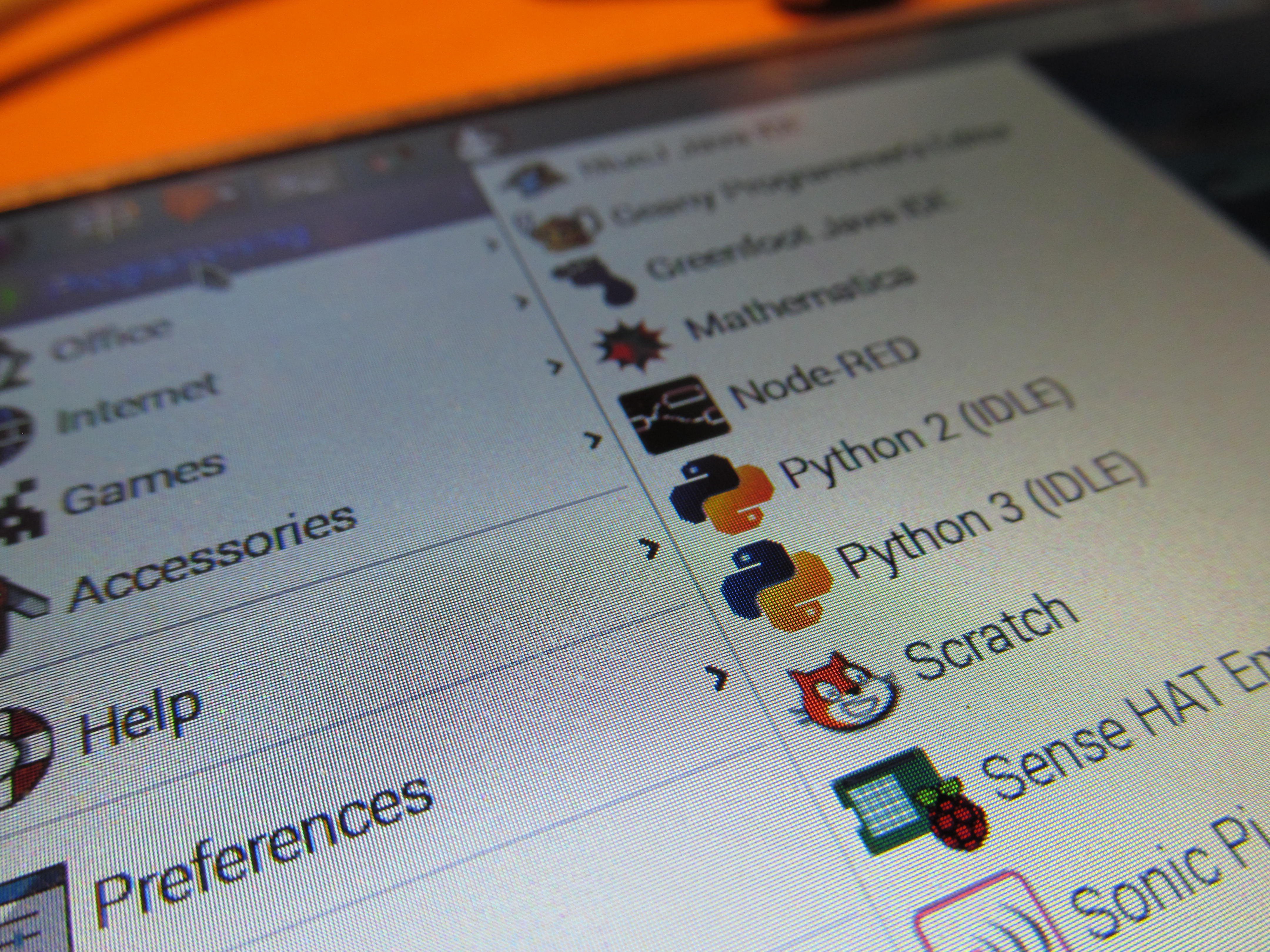
What about browsing hackaday on lynx?
![]() Chromium works here too, but due to small display it isn't very enjoyable to use.
Chromium works here too, but due to small display it isn't very enjoyable to use.
With SDCC and stm8flash I can edit, build and upload firmware on STM8 targets![]() or on arduino platform
or on arduino platform![]() I believe STM32 targets should work too, as well as PIC devices, using my programmer. Here you can see nano editor, editing my code to talk with STM32L011 MCU onboard, reporting battery voltage.
I believe STM32 targets should work too, as well as PIC devices, using my programmer. Here you can see nano editor, editing my code to talk with STM32L011 MCU onboard, reporting battery voltage.![]() Oh and don't forget to backups. Here is my take on SD card backup system.
Oh and don't forget to backups. Here is my take on SD card backup system.![]()
-
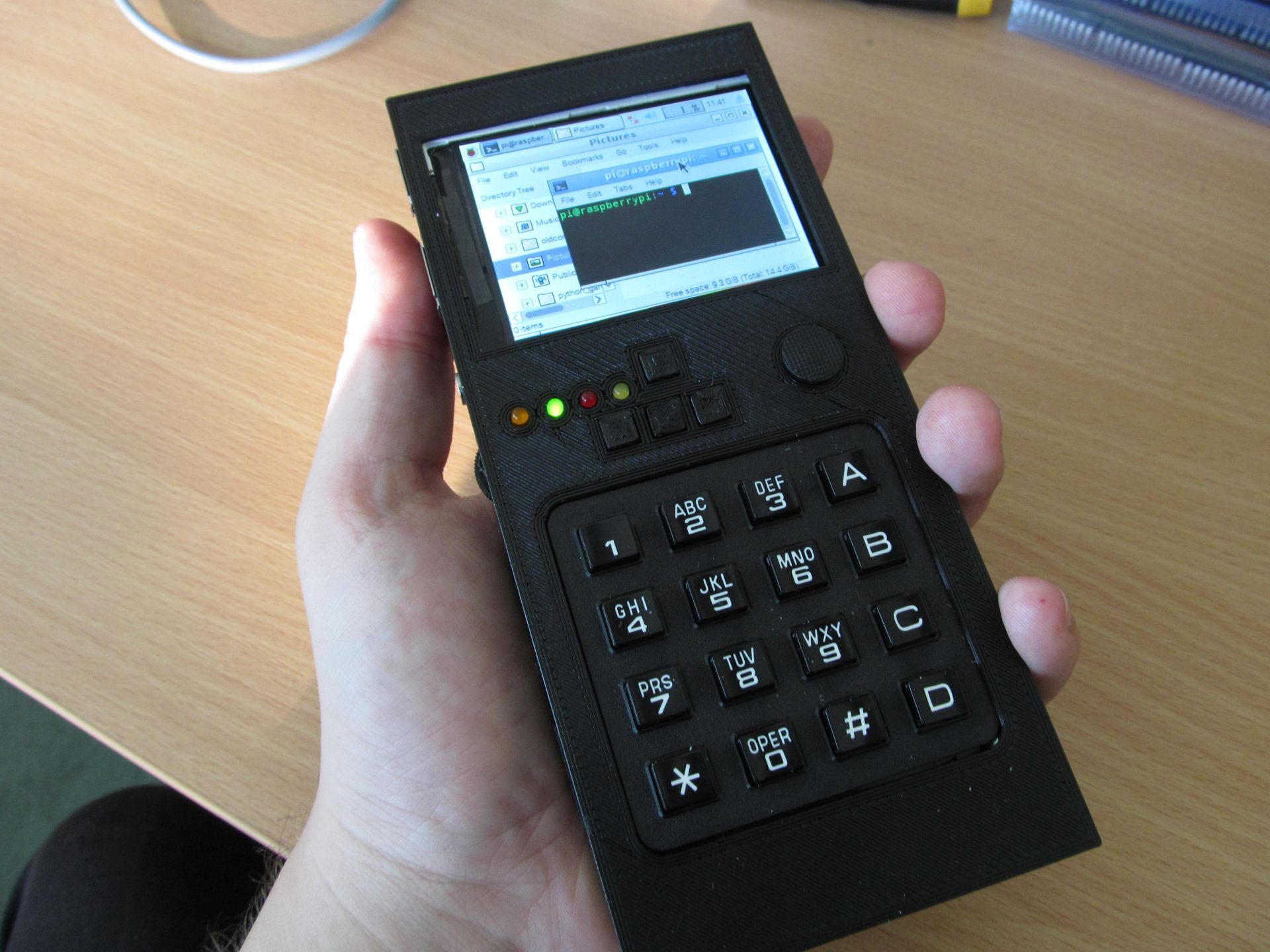
Project A, kind of finished
07/24/2017 at 11:38 • 0 commentsWell, I lied, because projects like this one are never actually finished. But let's say I'm not going to do any major rework from now.
It took one more board revision and a little bit of coding to come up with final hardware
![]() In the meantime, I made some minor changes to circuit, but the overall concept was still the same. Complete schematics is here https://github.com/jaromir-sukuba/pi_zero_computer/blob/master/hw/2i.sch.pdf but for sake of simplicity here you have hand drawn block diagram
In the meantime, I made some minor changes to circuit, but the overall concept was still the same. Complete schematics is here https://github.com/jaromir-sukuba/pi_zero_computer/blob/master/hw/2i.sch.pdf but for sake of simplicity here you have hand drawn block diagram![]() Heart of the device is Raspberry Pi Zero. The power is delivered from two LiPo cells in series, MCP73844 acting as charging IC and three TPS562200 are performing DC/DC down conversion to get three voltages:
Heart of the device is Raspberry Pi Zero. The power is delivered from two LiPo cells in series, MCP73844 acting as charging IC and three TPS562200 are performing DC/DC down conversion to get three voltages:
* 5V for RPi
* 5V for USB
* 3,3V for WiFi![]()
All of them are individually switchable from the STM32L011 and this is under RPi control via serial interface (native serial port of RPi), the STM can also report status of battery and charging controller. The STM32L011 itself is always powered via MCP1700 voltage regulator. Power consumption of the device in sleep mode is approximately 10uA.
![]()
Since RPi has only one USB port, I used FE1.1s USB hub IC to have USB WiFi RTL8188EUS module and USB keyboard/mouse devices along with two general purpose USB ports.
![]()
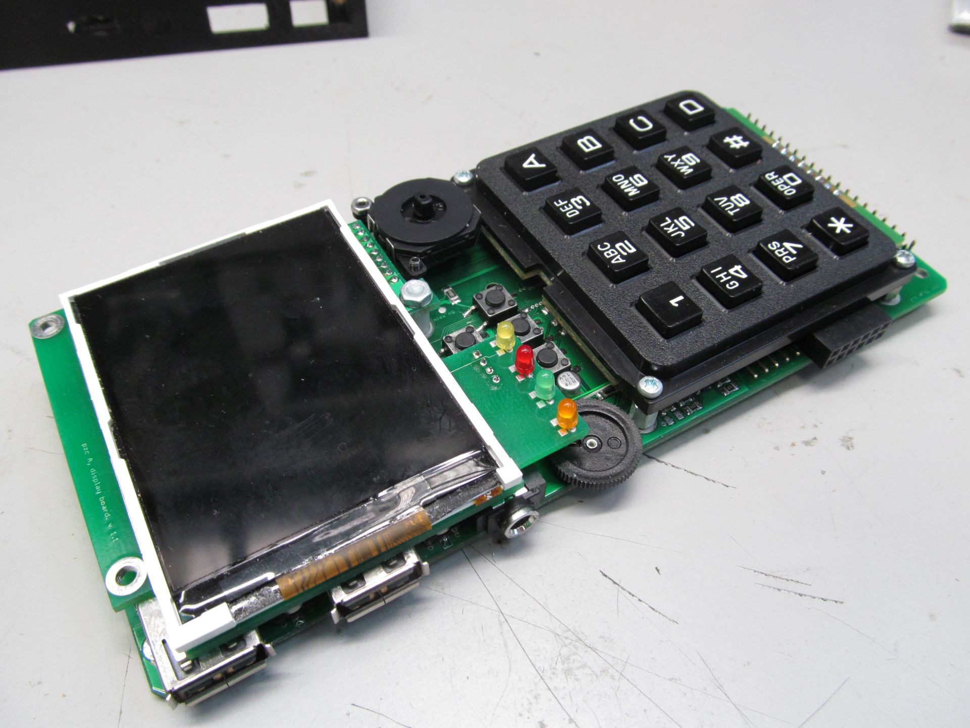
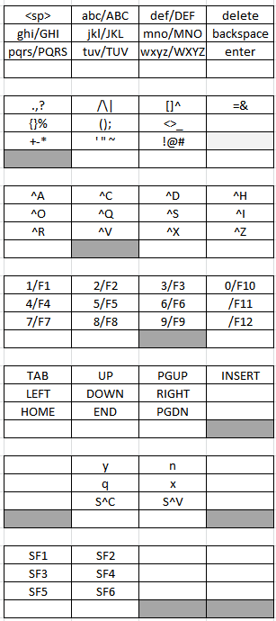
STM32F072 interacts with all tactile user IO (keyboard, joystick, mouse buttons) and acts as USB HID device for RPi, with interfaces to both keyboard and mouse. Since having 4x4 matrix keyboard (reasons why I opted for this keyboard are here and here) obviously brings some complications compared to full-blown 104 key keyboard, so I had to be a bit creative about the key combinations assignment. The bottom row keys act as modifier keys, but after a bit of trying, it is not that hard to remember.
![]() Gray keys denote pressed modifier keys. With no modifier keys pressed, you have to top layout - press key 7 once, you get 'p', press one more within 800ms, you get 'q', then 'r', then 's'. For special characters, press first modifier keys. I tried to arrange them in some logical manner, grouping related characters, like parenthesis or +-* symbols. For running executables in bash, press left modifier, hit first and second button, this types ./, then name of executable (using tab key saves you some typing). Forethink the executable filenames at least a bit and you can run most of them in a few key hits.
Gray keys denote pressed modifier keys. With no modifier keys pressed, you have to top layout - press key 7 once, you get 'p', press one more within 800ms, you get 'q', then 'r', then 's'. For special characters, press first modifier keys. I tried to arrange them in some logical manner, grouping related characters, like parenthesis or +-* symbols. For running executables in bash, press left modifier, hit first and second button, this types ./, then name of executable (using tab key saves you some typing). Forethink the executable filenames at least a bit and you can run most of them in a few key hits.
User interface is completed by TFT, with ILI9341 controller. It can be bought through usual Asian sources. There is nothing special about it, interfacing this kind of display has been done to death.
Audio is quite straightforward - the RC lowpass filter is no surprise to RPi users, TDA1308 acting as headphone amplifier is jelly-bean component, in intended application.
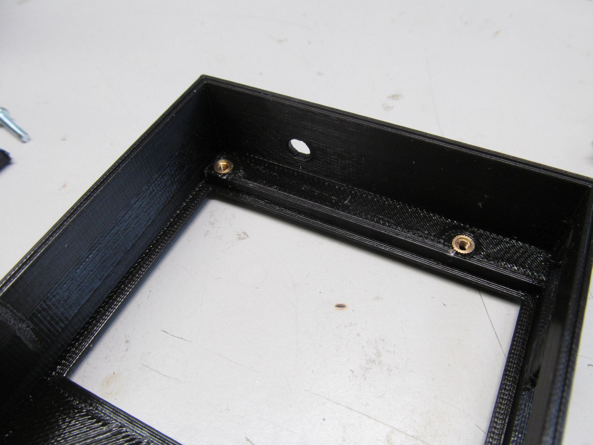
Enclosure is 3D printed, in three parts and is designed to keep the whole package together using 4 pieces of M2,5 screws![]() Threaded inserts are used to keep everything in place and to allow repeated teardown of the case, so much needed when tinkering with the device. Self tapered screws would be easier, but not as reliable choice here.
Threaded inserts are used to keep everything in place and to allow repeated teardown of the case, so much needed when tinkering with the device. Self tapered screws would be easier, but not as reliable choice here.![]()
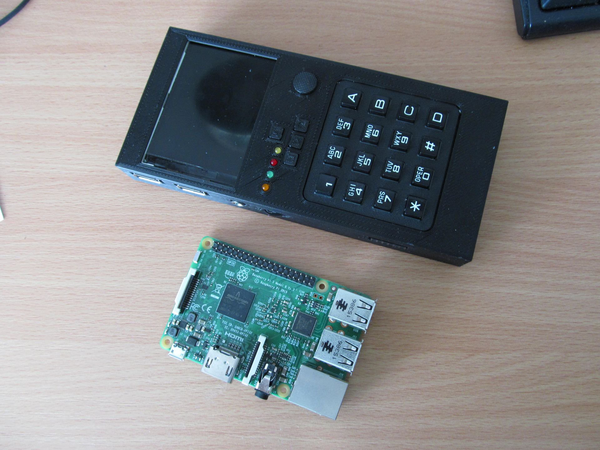
Overall dimensions are 16,3x7,3x2cm
![]()
Should have used BananaPi for scale, but RPi 3 should do the job too.
-
Project A, how it started
03/24/2017 at 18:02 • 0 commentsIntro
I decided to make two different portable computers with raspberry pi zero: one would have low-end user interface, perhaps low price and dimensions; another one with bigger display and keyboard, somehow resembling smaller laptop PC.
Project A is the smaller one. A lot of work has been done, but I couldn't find time to write logs here, so this is somehow retrospective description of how I did the design process. I also included some photos of prototype, to attract you to future logs ;-)
Project A, motivation
The project has to fit those constraints:
- raspberry pi zero as main processing unit
- at least 320x240 pixels LCD
- some form of keyboard and
- some form of pointing device to allow handheld use
- at least one USB 2.0 interface, with A type connector
- on/off switchable via single button, negligible current draw when off
- no touchscreens
- easy to source components
The last one is more difficult than it may look. Internet is not short of various displays and especially keyboard connected to all forms of whatever-pi class computers, but those are often gutted Chinese consumer items, like Xbox chatpad containing and PIC device back in the day, but nothing but asphalt blob on newer ones. While the difference is next to none for average consumer, it can be dealbreaker for open-source project, prepared for others folks to reproduce and build upon. So I want to build the thing using basic and obtainable components, available from multiple sources.
Implementation
The main limiting factors for overall dimensions of the device is the size of user IO - display, keyboard, pointing device, so I have to choose those ones first.
For display I experimented with PAL/NTSC displays from Chinese sources, designed for parking camera in your car. While perhaps usable for its intended purpose, it doesn't fit very much the "availability point" above and the picture quality leaves a lot to be desired, not to mention the fact the analog/digital interface takes a lot of current, what is a problem for portable battery powered gadget. The only real option here is digital interface. Another usual suspect is HDMI, but the connector is bulky, interface takes a lot of valuable juice too and brings price higher. Those two options don't require any configuration nor programming, so being more hardware than software oriented guy, I have to resort for "more complicated" methods (though being quite easy, in fact). I took inspiration from #Portable Raspberry PI Zero and bought some ILI9341 TFTs.
I ended up having three different sizes - 2,2", 2,4" and 2,8", all being electrically the same. The 2,2" is most common and cheapest of the three. The former ones are somehow more expensive, but the size of display is IMHO good fit for this project, especially in 2,8" variant. I debugged the interface on Raspberry pi 3, easy to use for it's populated 0,1" header and Ethernet interface for headless access.
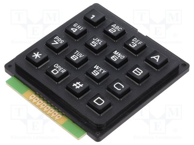
Keyboard is problem as usual. Calling @davedarko as reference for second time, I'm not the only one having this problem. See me reply in here for some more background info. Long story short, I decided to use the same keyboard as on my #Pavapro - portable AVR programmer project. It is available locally and through Asian suppliers and seems to be more-less jellybean part.
![]()
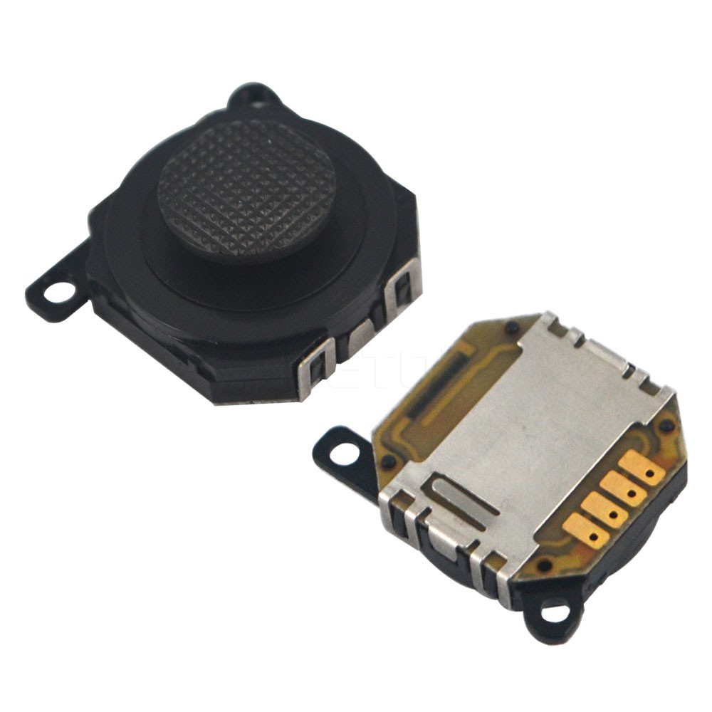
For pointing device, I opted for joystick, moving mouse cursor in similar way as pointing stick on some notebook computers. After a long search, I decided to use joystick designed to be replacement part of PSP1000 and others. While it is exception to the "availability rule", it is available in huge amounts from a lot of sources, including local ones, so - while not being particularly happy about it - I had to accept it as solution. It's dimensions and electric interface are well defined, so future replacements will be good fit too.
![]()
Having, the main parts identified, I had to arrange it somehow. I thought of three different variants:
1, Display on top, keyboard left and joystick right
![]()
2, Landscape version, keyboard on left, display top right, joystick bottom right
![]()
And third option (you can guess it's the winning one), display, joystick and keyboard from top to bottom
![]()
I printed all three mock-ups on paper and tried to how it's going to fit in my hand. Not surprising, the classic design, somehow resembling old calculator or phone, is probably giving the best ergonomics from all of those.
Brief summary of smaller details
Here I was at position to solve smaller details. Those details are suited for separate log, though - so take this as a brief summary of what I did.
I wanted to connect the keyboard in "simple" way, with no special device drivers for raspberry pi, USB seemed like logical choice - so i had to implement an USB HID device. The 12-key layout (actually 16-key, but 4 of them used as modifier keys) makes it a bit harder, as normal keyboards usually have one key per character, but it's nothing unmanageable. I did the same for pavapro. Somehow more complicated was to make "two-headed" HID device, allowing both keyboard and mouse action via single USB device, realized in STM32F072C8 device.
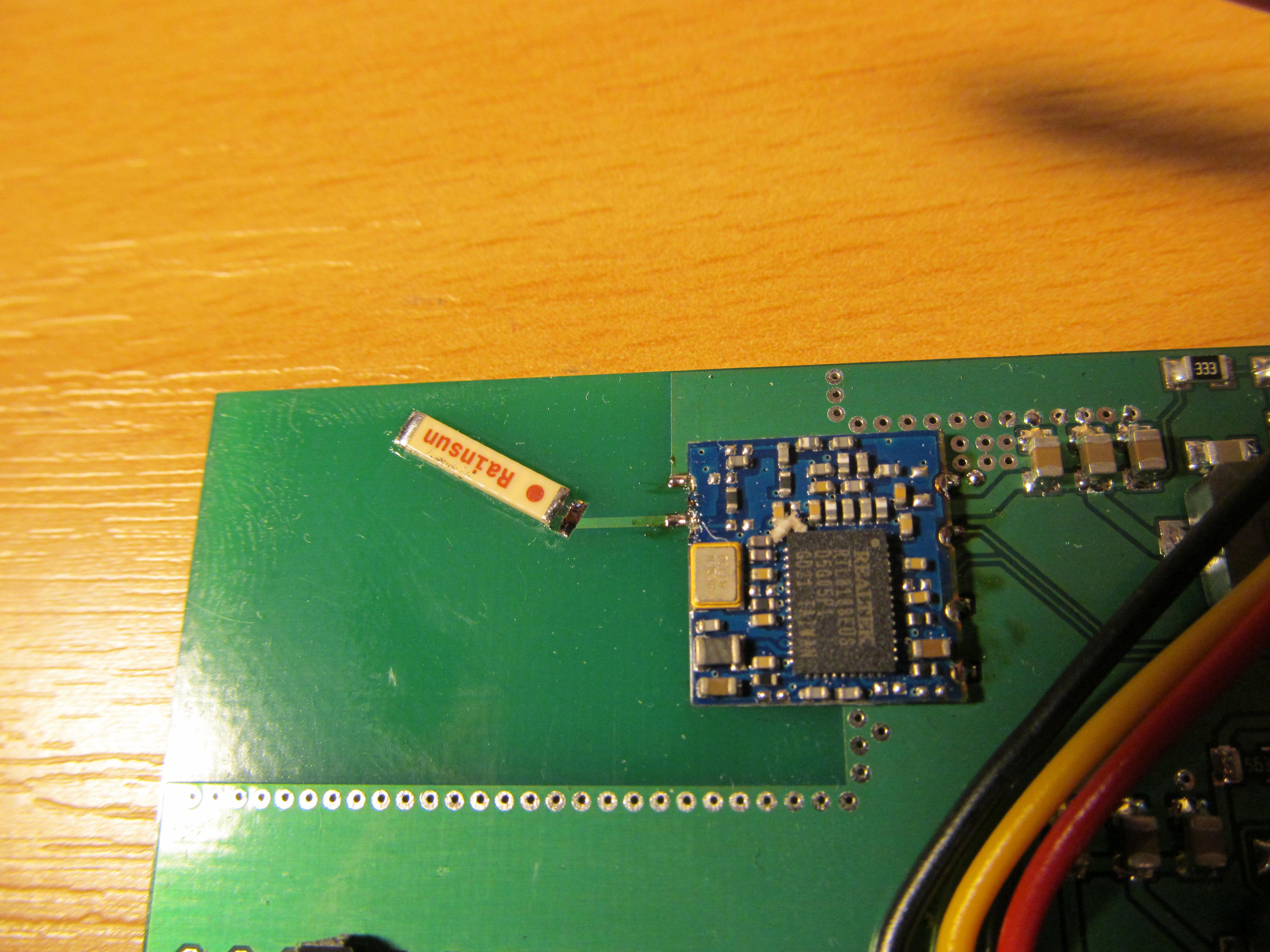
For WiFi, I opted for RTL8188EUS module, available at usual Asian sources. It is also common in many tablets or small computers on market, it has even similar module in the same package (88W8782) so I qualified it as jelly-bean part.
In order to have somehow useful computer, one USB port is not enough, especially when consumed by on-board WiFi module and keyboard interface. So I added USB hub with four downstream ports, with FE1.1s chip. This one seems to be popular in "diy-handheld-console" guys too.
For all this, I need some kind of power. I opted for powering from two Li-Po cells in series, with three step-down switched TPS562200 regulators - 5V for Raspberry pi, 5V for USB and 3,3V for WiFi module. All those voltages are switched on or off via another MCU, STM32F030F4, capable of communicating with Raspberry pi, so it can turn itself off, if needed. The MCU can also monitor battery voltage and battery charging.
PCB
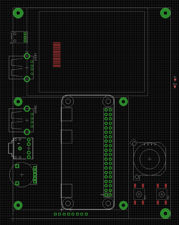
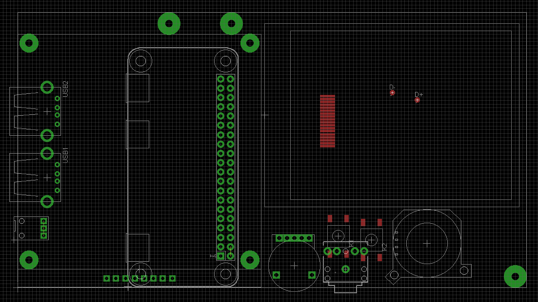
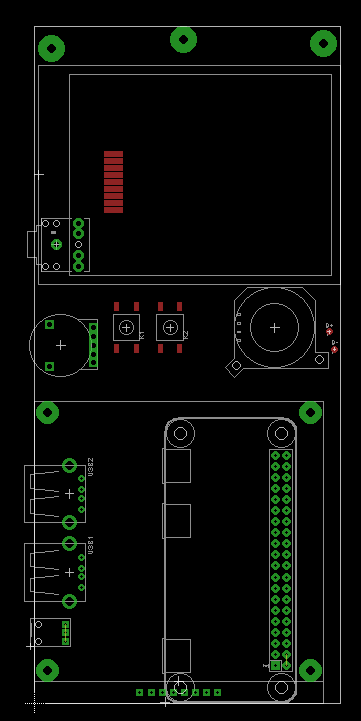
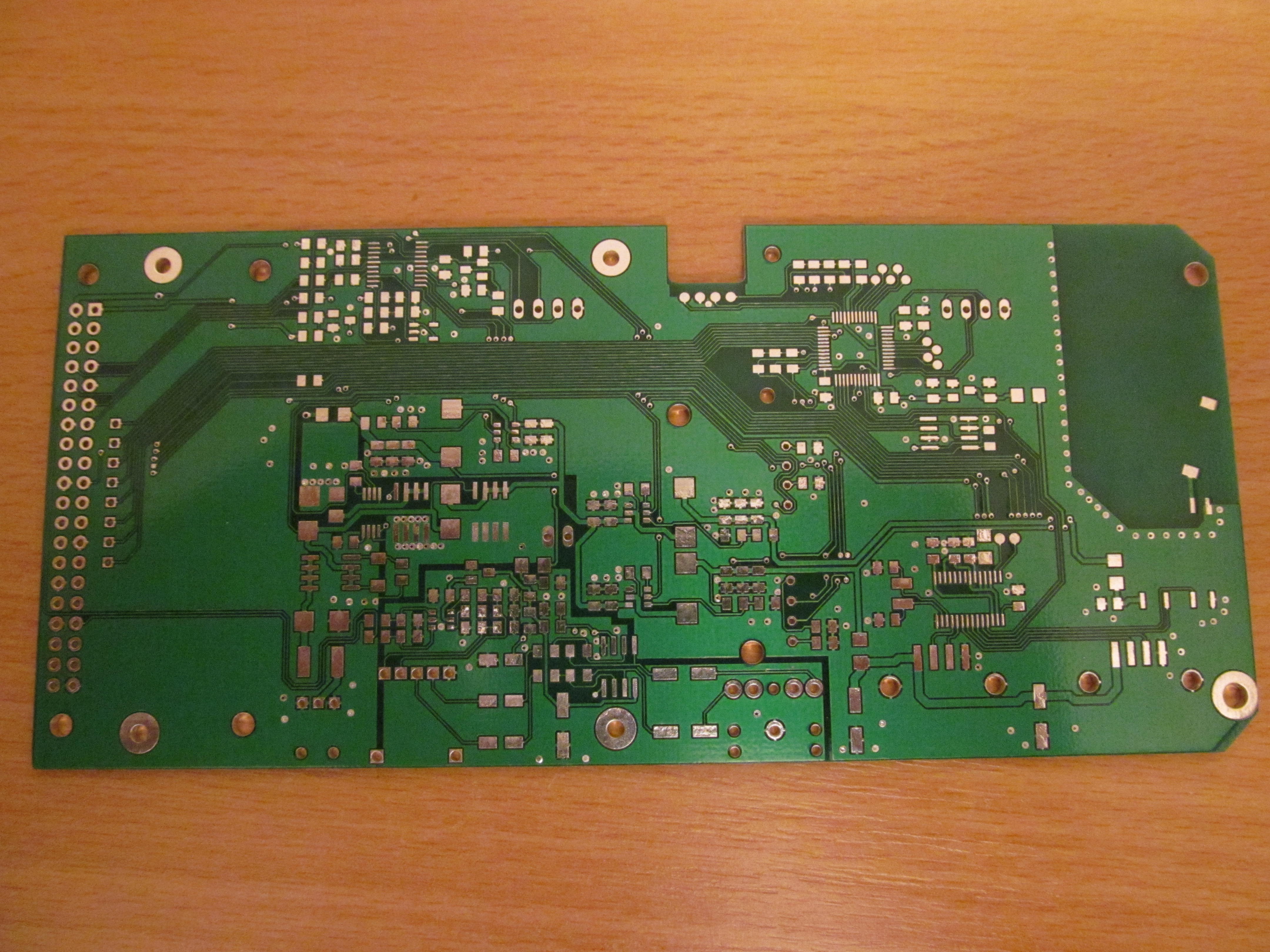
I took a few hours at Eagle and designed the PCB.
![]()
This is bottom side, top side being mostly groundplane. I ordered it and...
![]()
..magic happened, PCBs were at my hands.
![]()
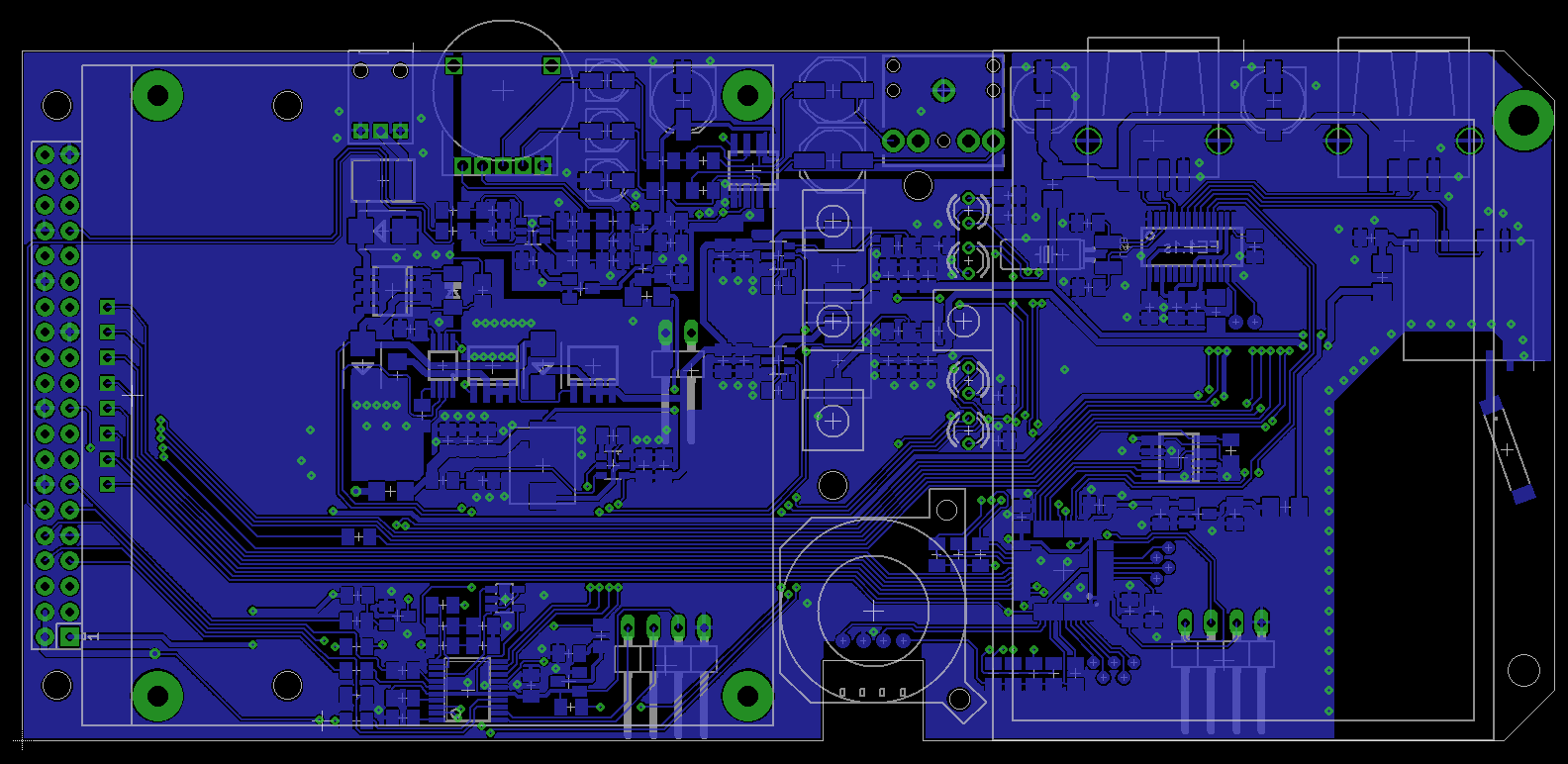
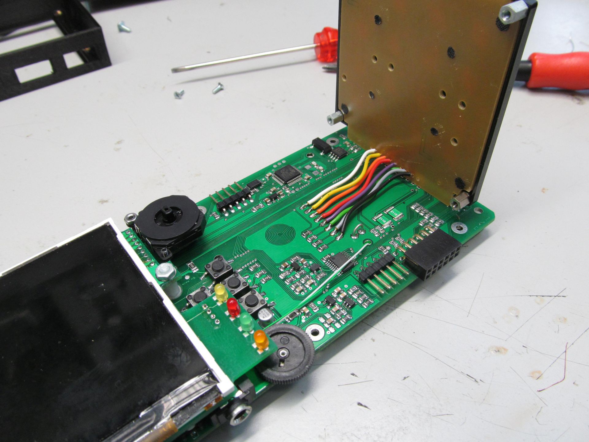
It didn't took me long to populate the board and correct some minor fuck-ups
![]()
and to get it running
![]()
![]()
The codebase for both MCUs is still far from being complete, but I'm working on it. Stay tuned.
-
First log
01/14/2017 at 23:15 • 0 commentsI actually started this project in november or so, but haven't got myself to write something about it. Then, 1kB contest appeared and I was busy by squeezing as much code into 1024B as possible, so 1GB memory rpi zero received only little of my interest.
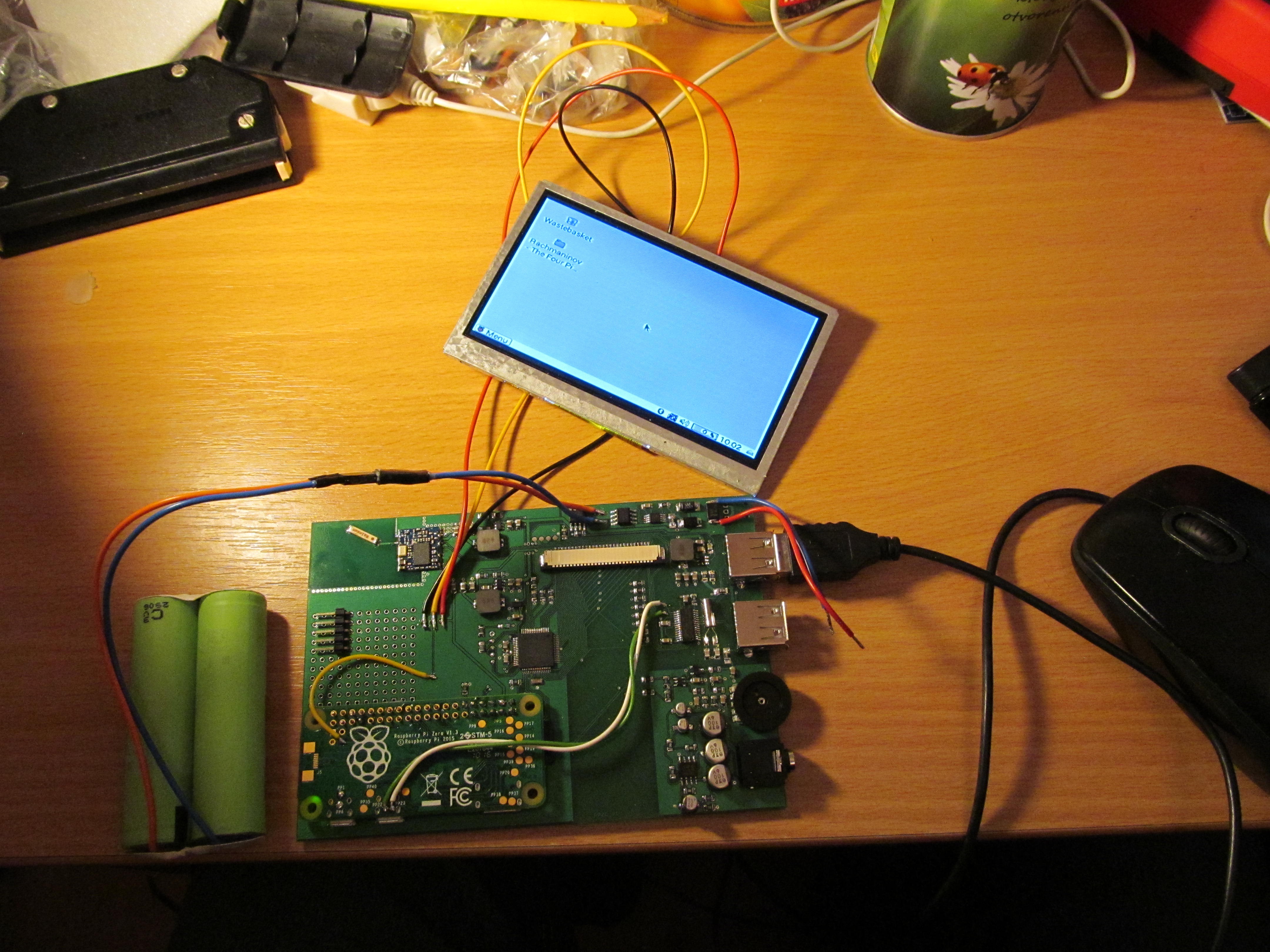
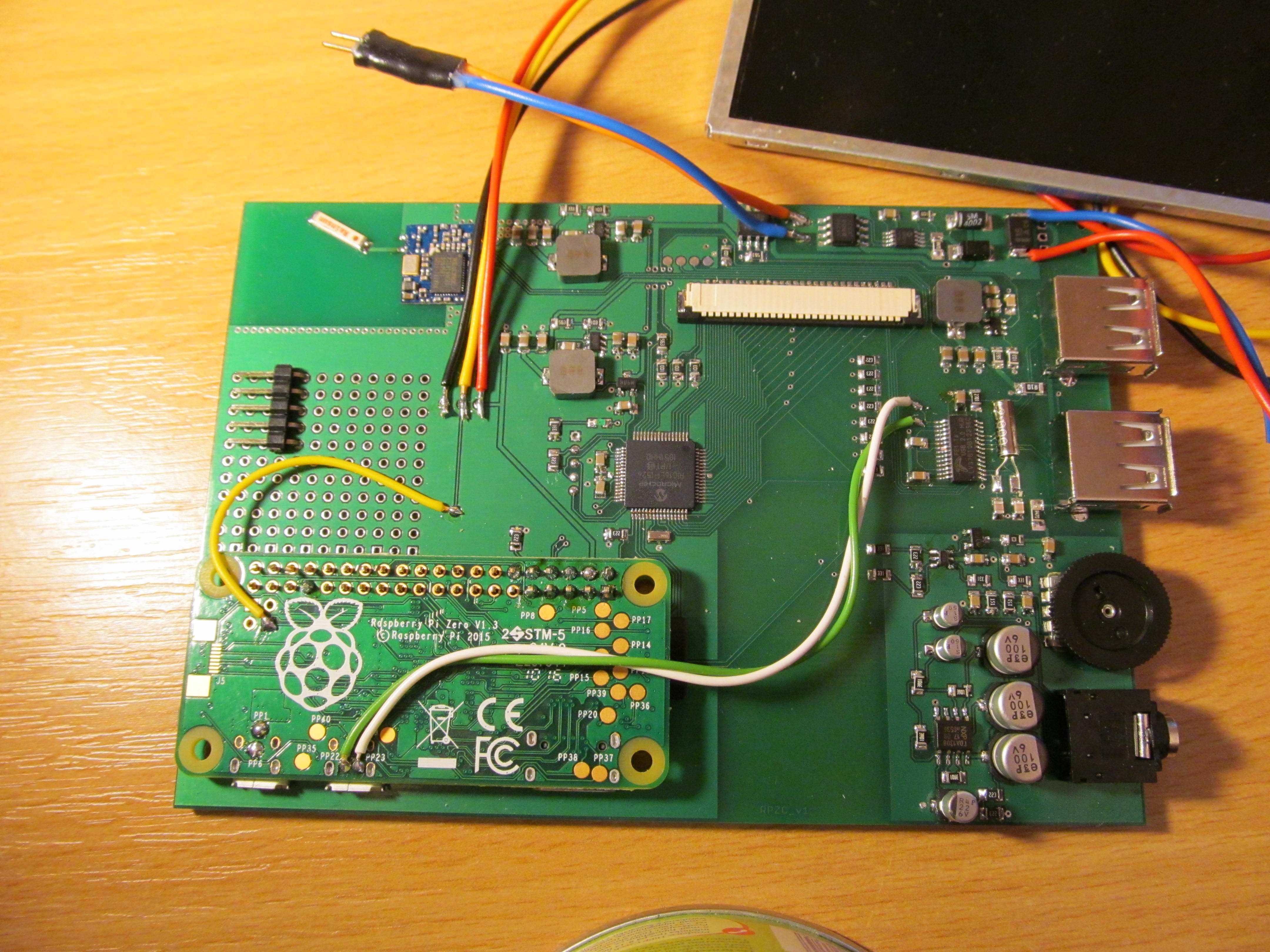
I made board hosting rpi zero, USB hub, USB Wi-Fi module, two USB A ports, audio filter and amplifier for headphones, power supplies for all the goodies and microcontroller to control it all.
![]()
Honestly, I'm not exactly sure why I opted for USB WiFi module instead of ESP8266
![]()
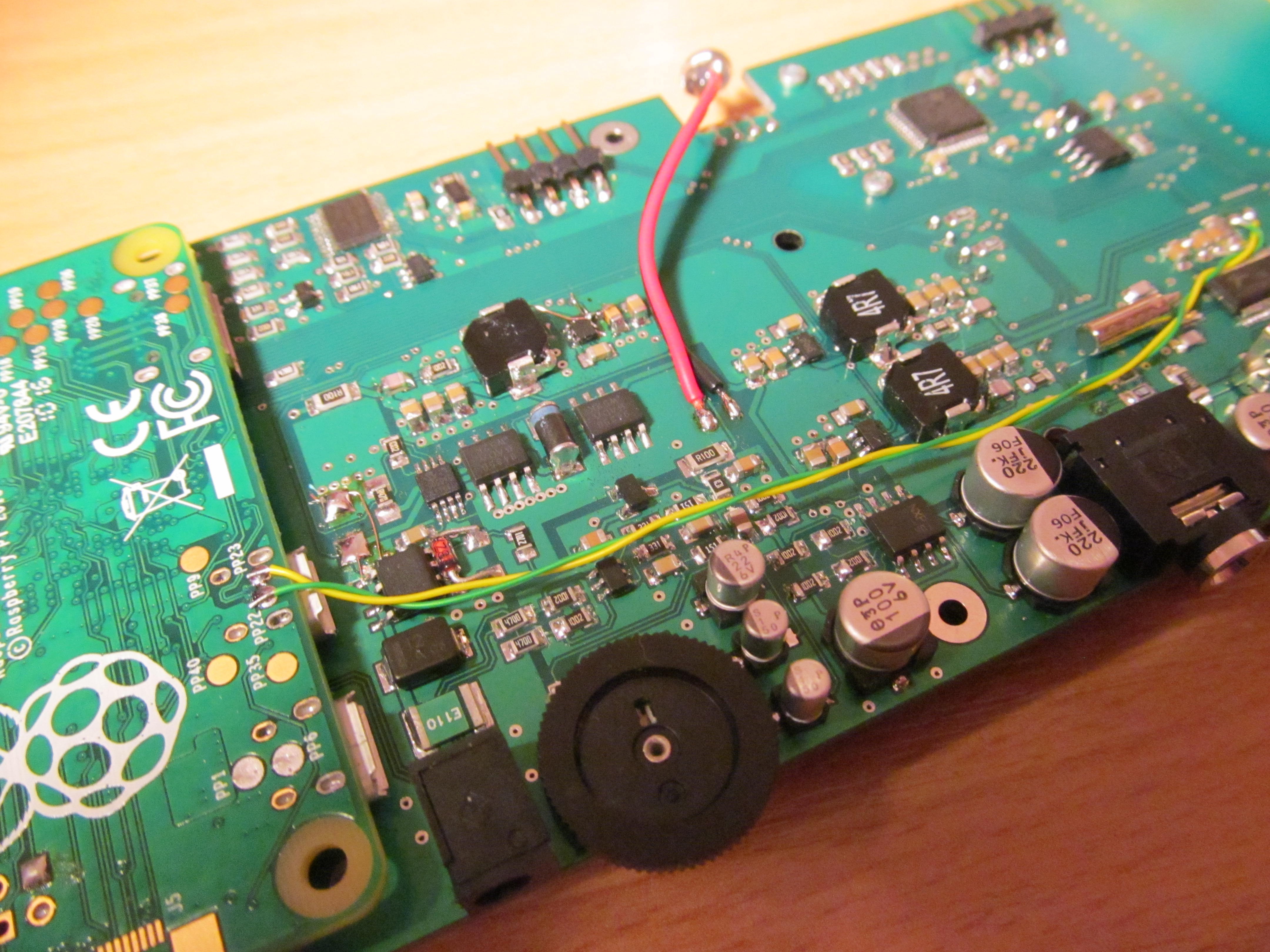
Battery is two 18650 cells in series, here is charging/switching circuit for it. In bottom right corner is 5V DC/DC supply for USB. There are two more DC/DC supplies - 5V for rpi, 3,3V for WiFi.
![]()
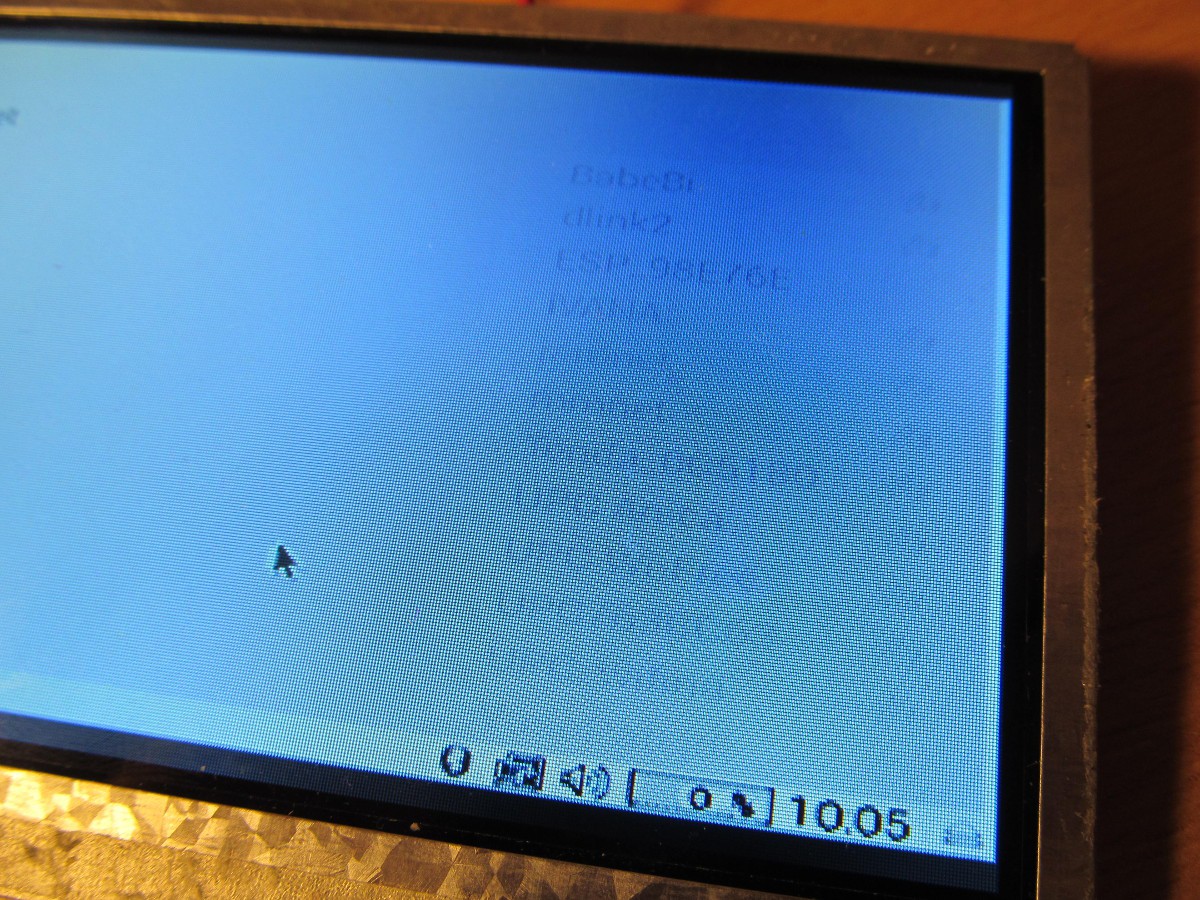
Display is 4,3" composite input. The picture quality is not good at all. Higher contrast transitions are blurry and display is leaving "ghosts", look
![]()
leaving the window here for a minute or so and hiding it
![]()
By the way, the original display was more than poorly made. It's internal regulator was set to 4V, supply voltage for display controller was dropped by serial resistor. The worst crap I've ever seen. Resistor wasn't dropping enough, chip got 3,6V and overheated, drawing too much current. The DC/DC converter for backlight was fed via another dropping resistor, decreasing its efficiency. Replacing the series resistor by proper 3,3V regulator and letting the DC/DC fly by removing its resistor, I saved approximately one third of display power consumption. Another saving could be introduced by replacing LDO by switching DC/DC, but probably I will not go this way, as the composite output is really poor.
Ther
![]()
There is also PIC16LF1526 on board, running always from its own low-power linear regulator, drawing 2uA when idle.
Its tasks are: turning other power rails on and off, scanning keyboard even when rpi is off, doing keyboard interface to rpi, measuring power supplies. Currently it just turns the supplies on and idles forever.
This thing isn't doing anything exciting right now, is incomplete, but will serve as guinea pig for another experiments.
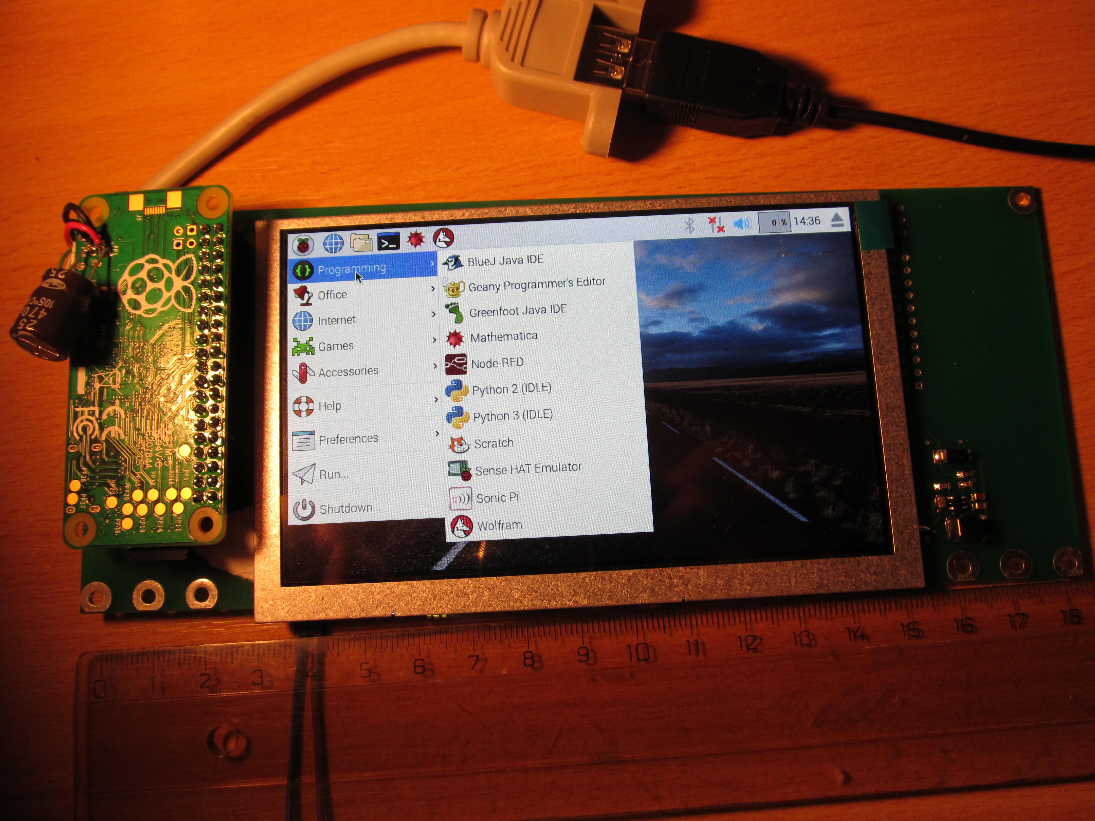
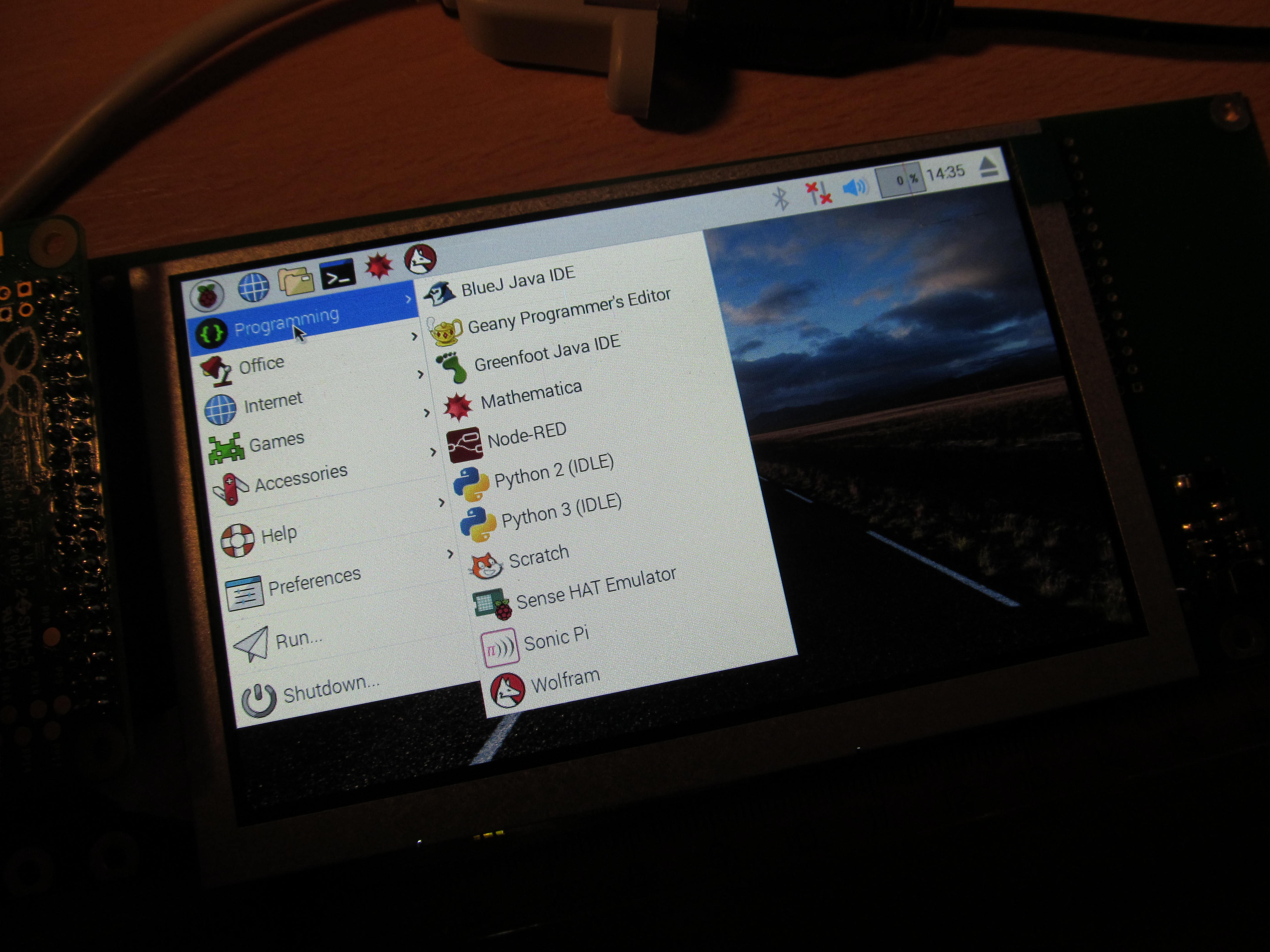
raspberry pi zero handheld computer
Since rpi zero is unobtainum, I got a few.
 There is really nothing but single resistor on bottom side
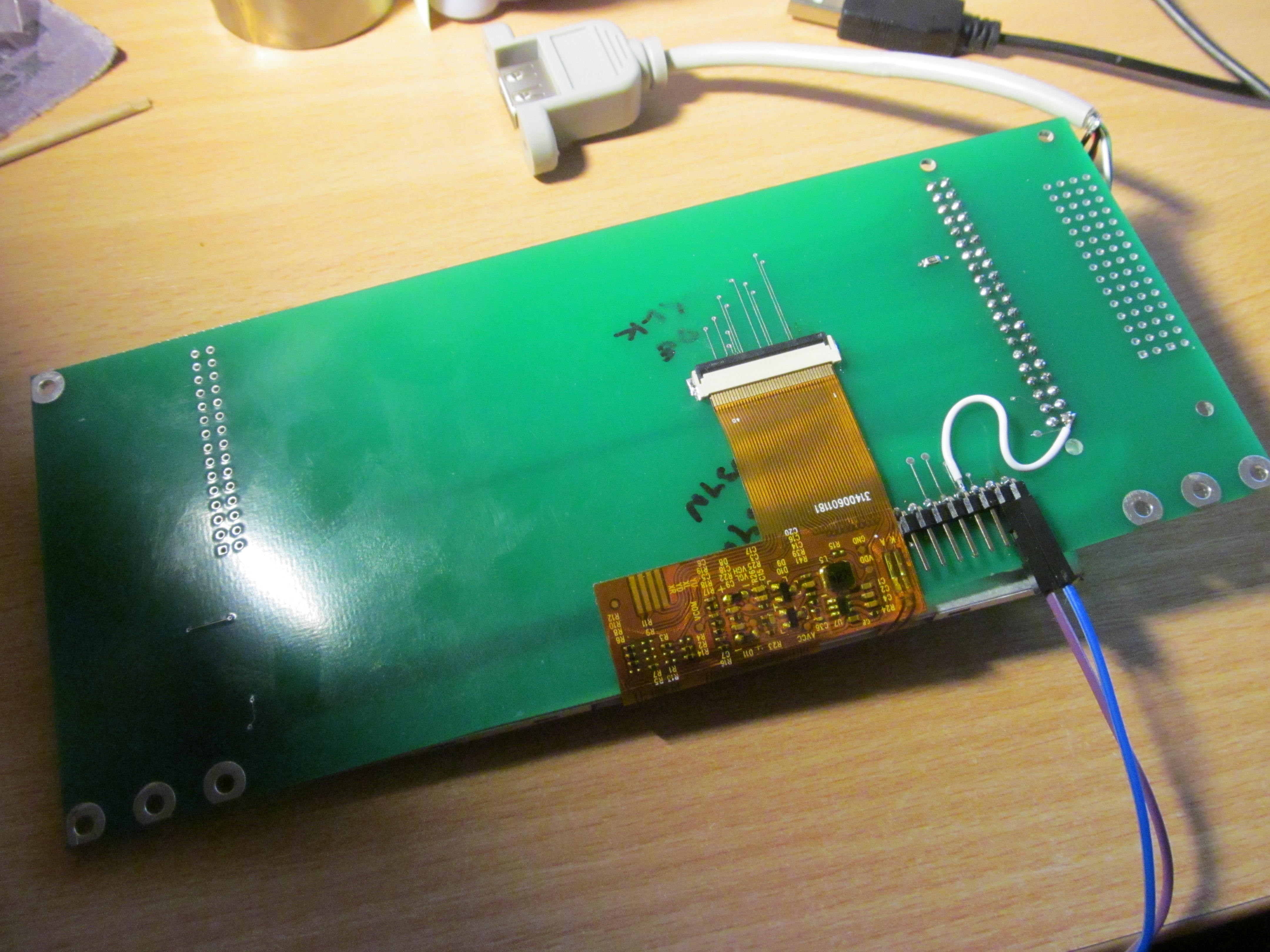 The whole setup takes approximately 1,5 Watts during run. It could be lower, but this is still manageable
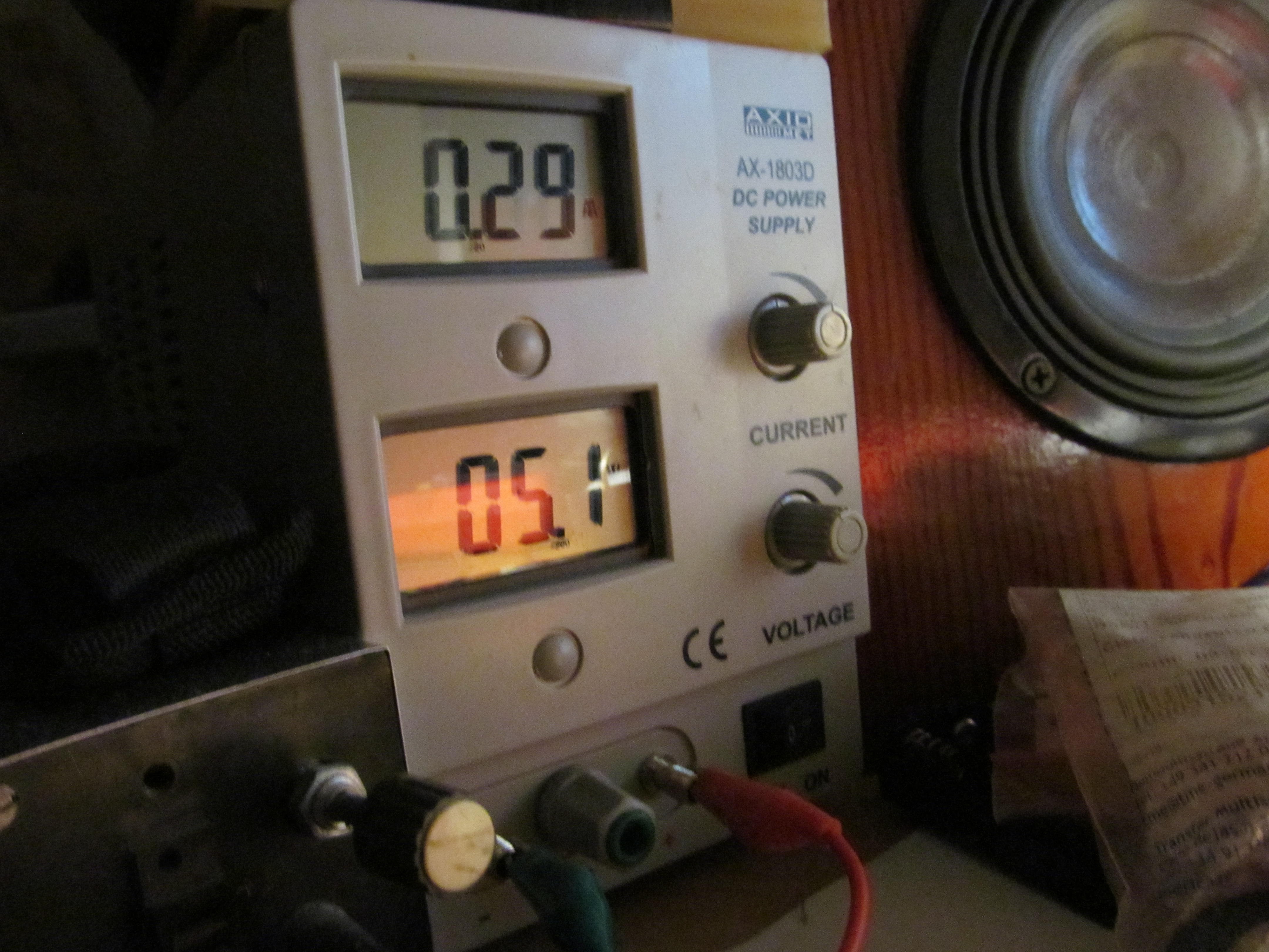 Now I'm in the process of adding keyboard and pointing device to this - not the joystick I had on project A, but touchpad. This is going to be non trivial process, as most of the GPIO pins are taken by DPI interface and this time I don't want to run everything from internal USB. Stay tuned.
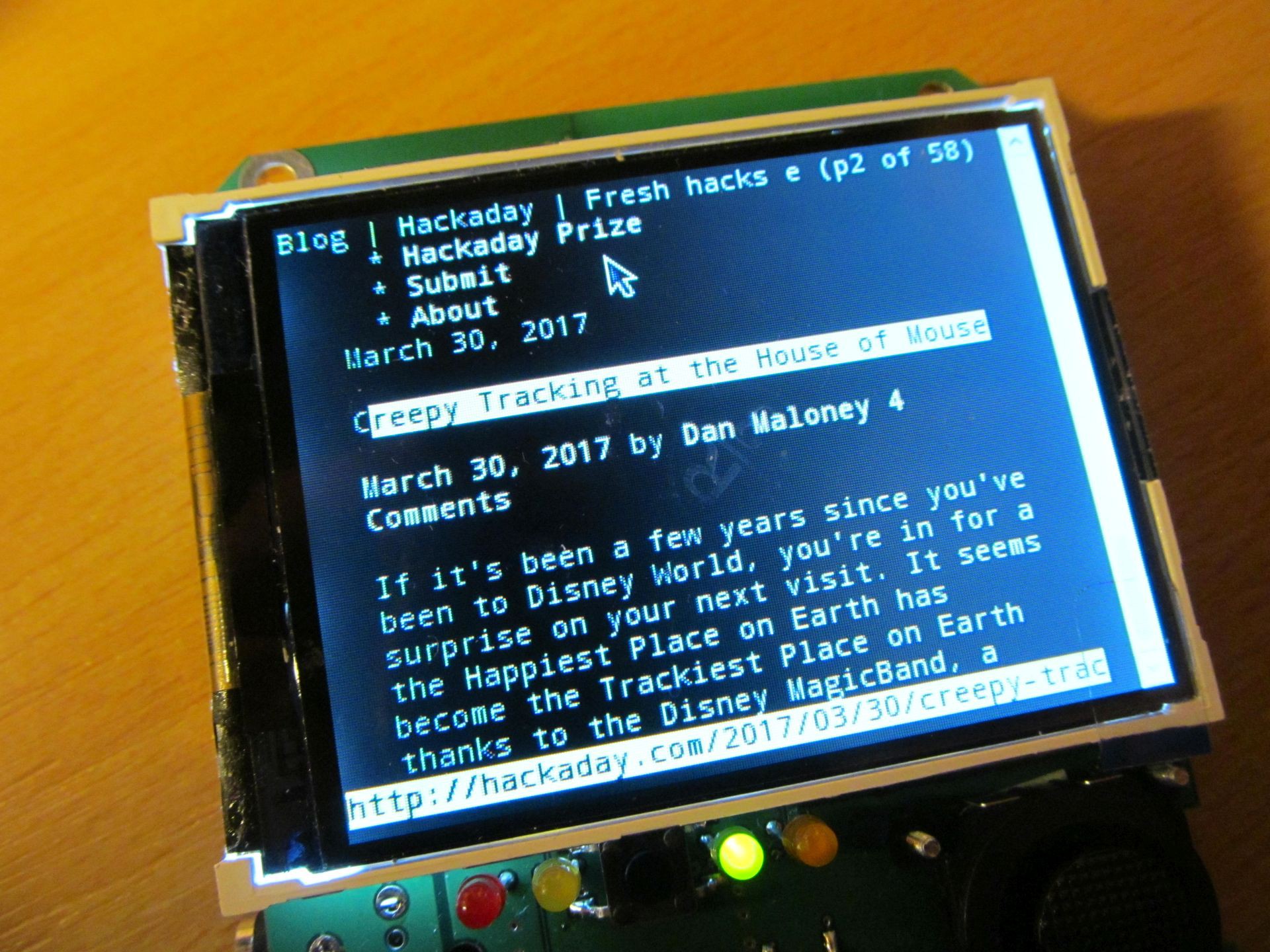 Chromium works here too, but due to small display it isn't very enjoyable to use.
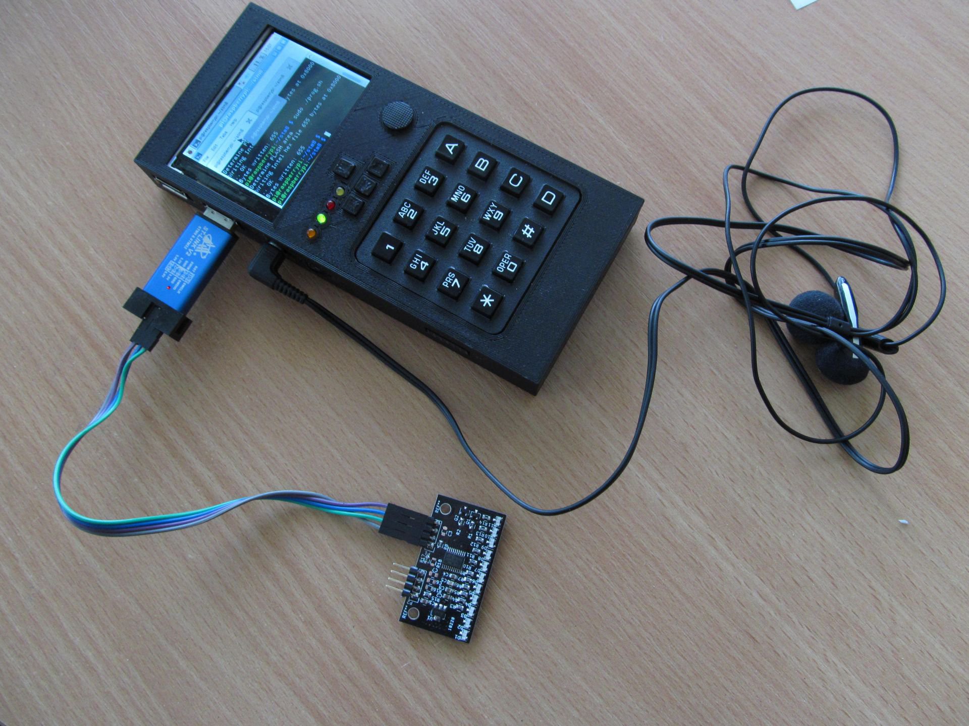 or on arduino platform
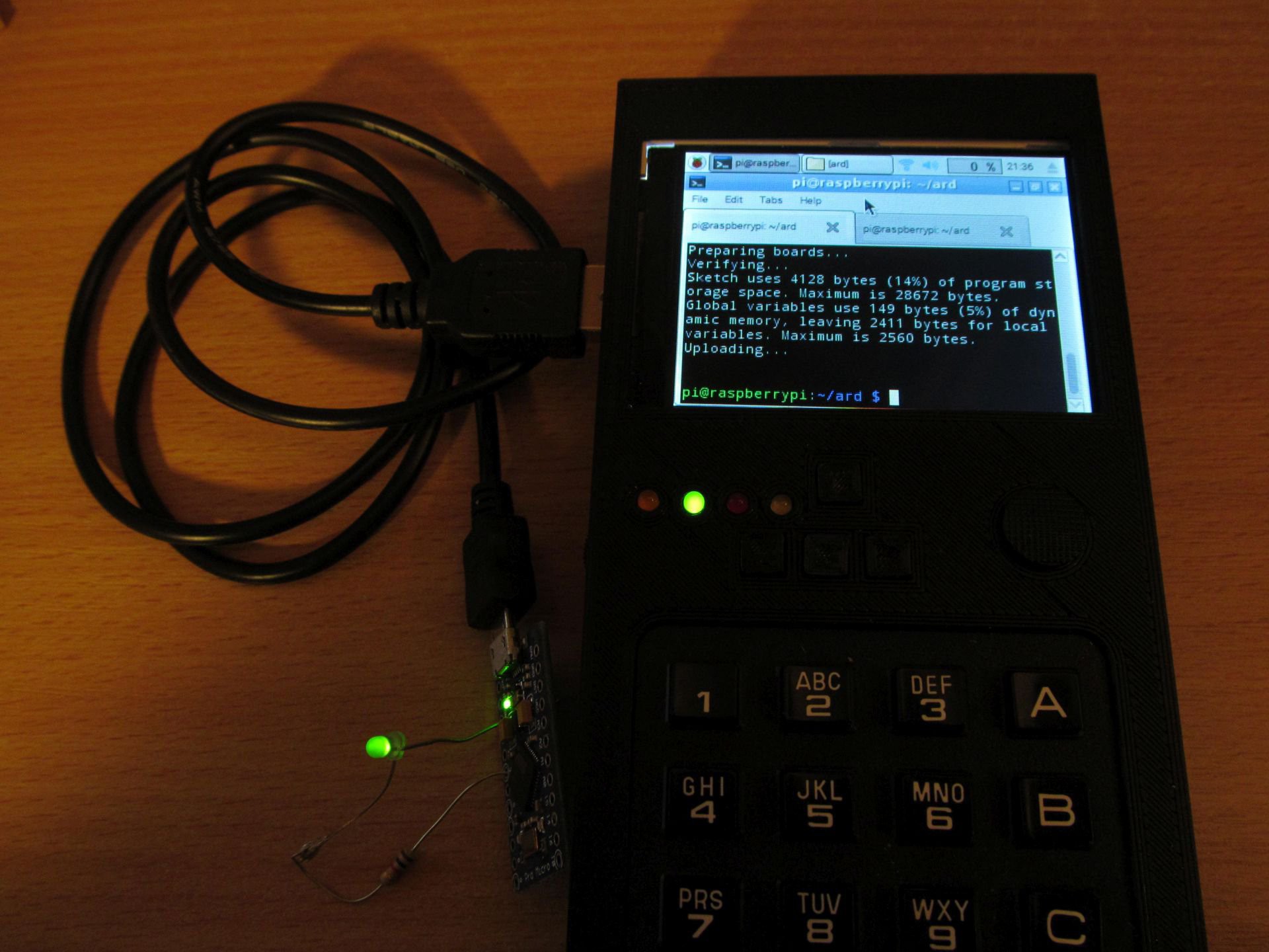 I believe STM32 targets should work too, as well as PIC devices, using
 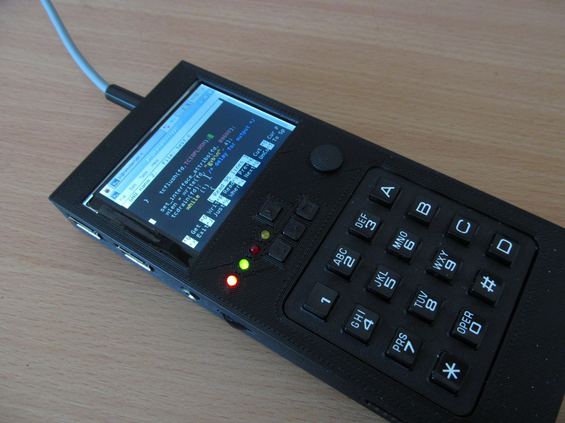 Oh and don't forget to backups. Here is my take on SD card backup system.
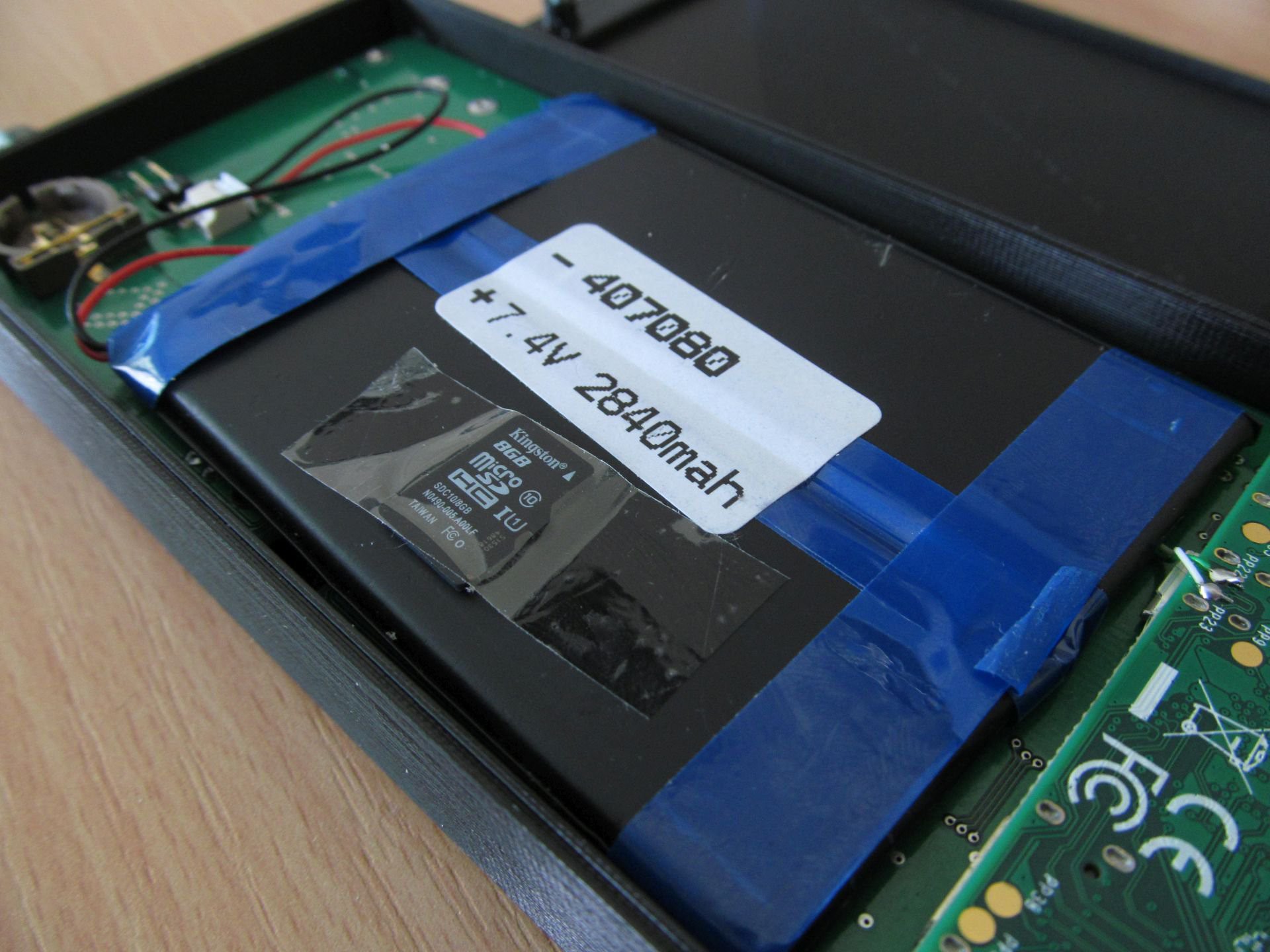
 In the meantime, I made some minor changes to circuit, but the overall concept was still the same. Complete schematics is here
 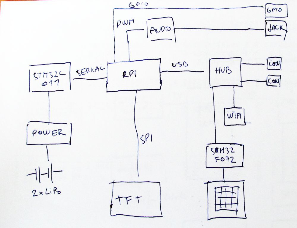 Heart of the device is Raspberry Pi Zero. The power is delivered from two LiPo cells in series, MCP73844 acting as charging IC and three TPS562200 are performing DC/DC down conversion to get three voltages:
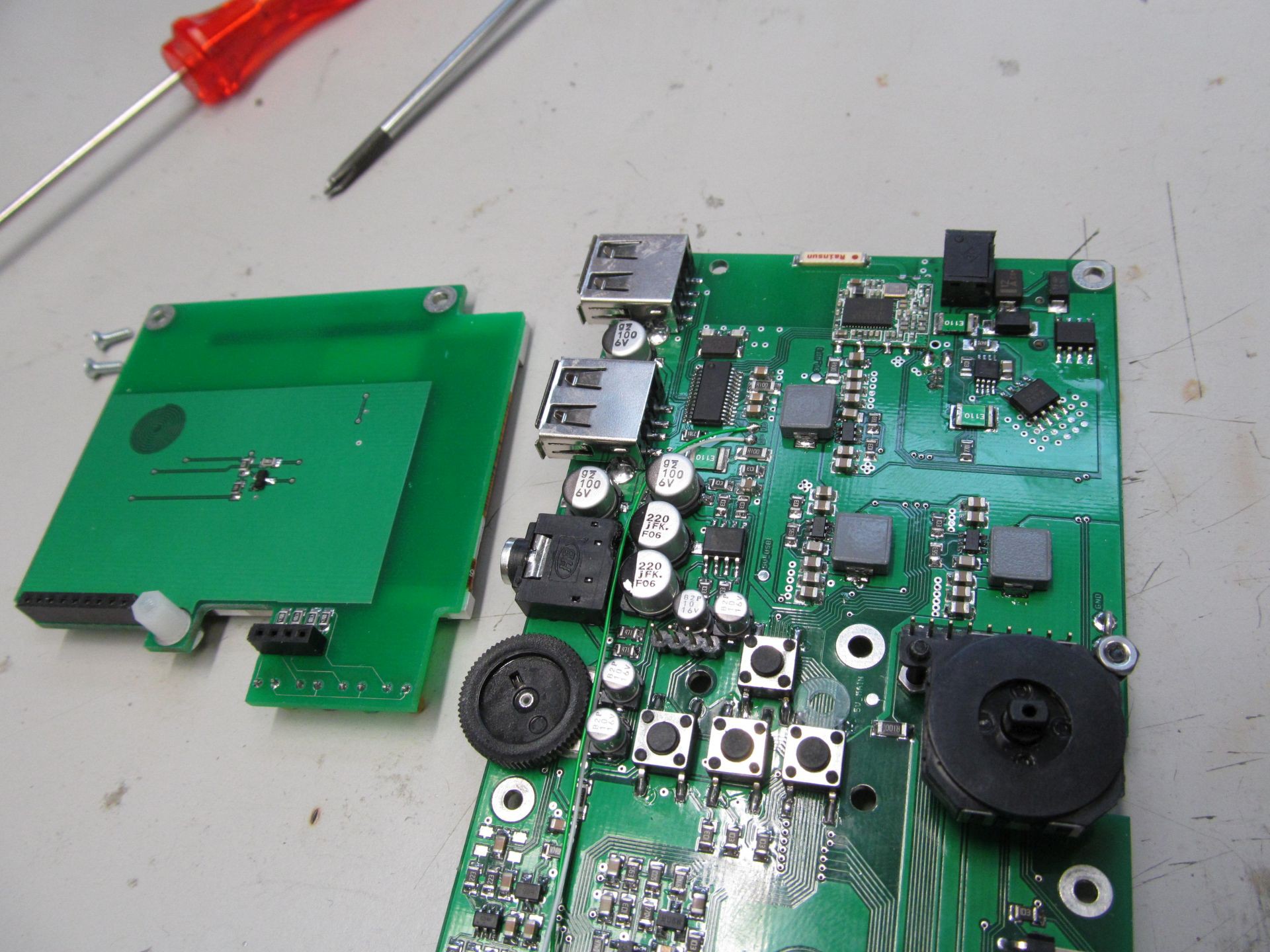
 Gray keys denote pressed modifier keys. With no modifier keys pressed, you have to top layout - press key 7 once, you get 'p', press one more within 800ms, you get 'q', then 'r', then 's'. For special characters, press first modifier keys. I tried to arrange them in some logical manner, grouping related characters, like parenthesis or +-* symbols. For running executables in bash, press left modifier, hit first and second button, this types ./, then name of executable (using tab key saves you some typing). Forethink the executable filenames at least a bit and you can run most of them in a few key hits.
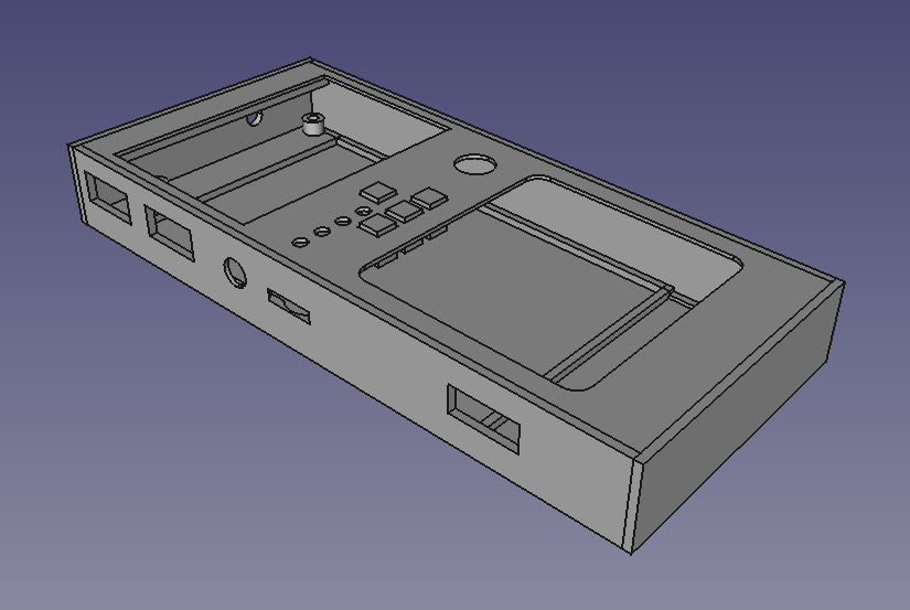 Threaded inserts are used to keep everything in place and to allow repeated teardown of the case, so much needed when tinkering with the device. Self tapered screws would be easier, but not as reliable choice here.