-
Hardware Testing - IT WORKS!
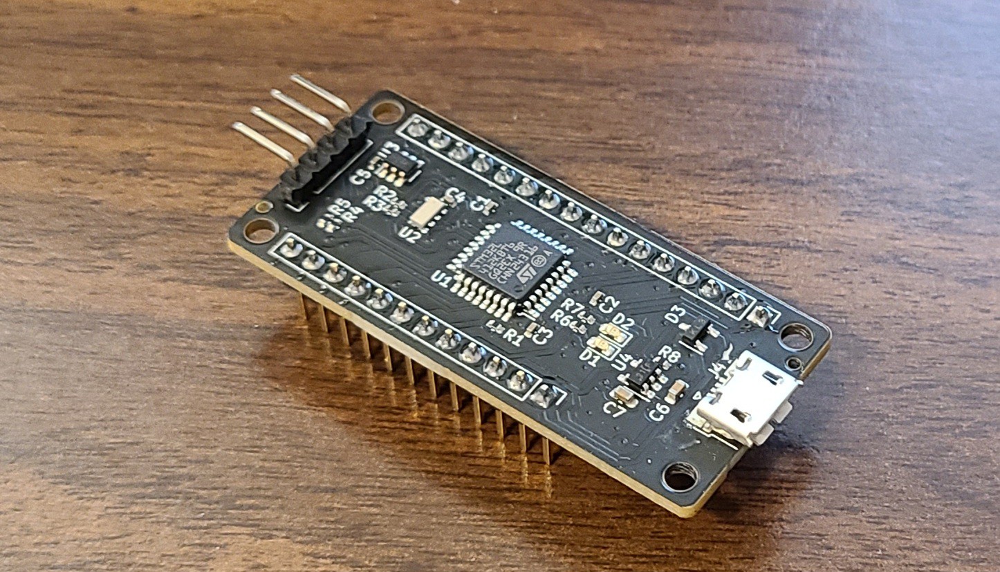
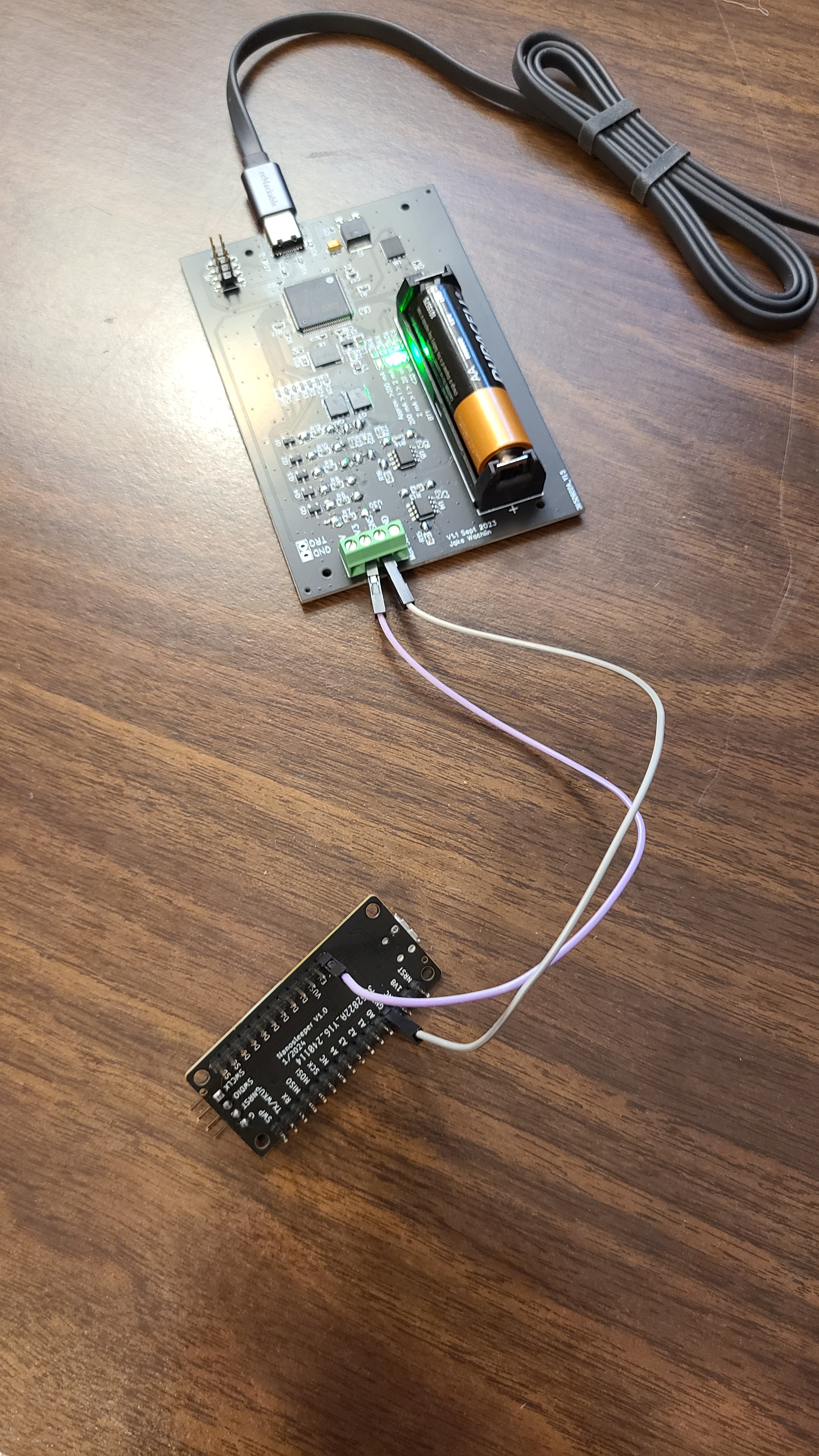
01/27/2024 at 21:12 • 0 commentsThe PCBs have arrived assembled from JLCPCB and look great! I added the headers and started programming. My goal was to simply demonstrate the ability to achieve <100nA deep sleep while waking up after a certain time. I used my Metashunt power measurement tool to test it.
![]()
![]()
![]()
![]()
The code used for this test is simple, and shown below.
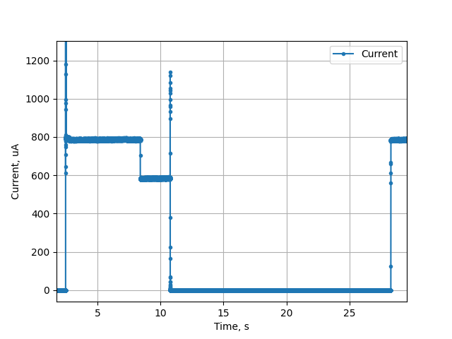
  // Toggle LED to indicate awake
  HAL_GPIO_WritePin(D12_GPIO_Port, D12_Pin, GPIO_PIN_SET);
  HAL_GPIO_WritePin(D13_GPIO_Port, D13_Pin, GPIO_PIN_SET);
  HAL_Delay(5000);
  HAL_GPIO_WritePin(D12_GPIO_Port, D12_Pin, GPIO_PIN_RESET);
  HAL_GPIO_WritePin(D13_GPIO_Port, D13_Pin, GPIO_PIN_RESET);
  HAL_Delay(2000);

  // Set up RTC, checking if it's already been set up
  bool is_initial_setup = true;
  uint32_t current_time_utc = 1705968815;
  bool rv_3028_setup_ok = init_rv_3028_c7(hi2c1, current_time_utc, is_initial_setup);


  // Go to shutdown mode, with pin wakeup.
  HAL_PWR_DisableWakeUpPin(PWR_WAKEUP_PIN1);


  /* Enable wakeup pin WKUP1 */
  HAL_PWREx_EnableGPIOPullDown(PWR_GPIO_C, PWR_GPIO_BIT_14);
  HAL_PWREx_EnableGPIOPullDown(PWR_GPIO_C, PWR_GPIO_BIT_15);
  HAL_PWREx_EnableGPIOPullUp(PWR_GPIO_A, PWR_GPIO_BIT_0);
  HAL_PWREx_EnablePullUpPullDownConfig();
  HAL_PWR_EnableWakeUpPin(PWR_WAKEUP_PIN1_LOW);
  HAL_PWREx_DisableInternalWakeUpLine();

  /* enter shutdown */
  __HAL_RCC_PWR_CLK_ENABLE();
  __HAL_PWR_CLEAR_FLAG(PWR_FLAG_WUF1);
  HAL_PWREx_EnterSHUTDOWNMode();
At the start, I turn on both LEDs for 5 seconds, then turn them off with a busy wait for 2 seconds. I then call the init_rv_3028_c7 function, which sets the time on the RTC and configures it to send an interrupt to the WKUP1 pin on the microcontroller after 15 seconds. And the short version of it is - IT WORKS! We get <100nA deep sleep while waking up later based on RTC time. The RTC can wake the device with the periodic timer up to a limit of 4095 minutes (~2.8 days). The image below shows a full single cycle. With both LEDs on, the system requires about 800uA from the 3.3V I provided to the BAT input on Nanosleeper. With the LEDs off, but busy waiting at 4MHz, the system takes about 600uA. There is a spike in current at ~12s when the microcontroller communicates with the RTC over I2C, and then the system enters the deep sleep mode. 15 seconds later, it wakes again!
![]()
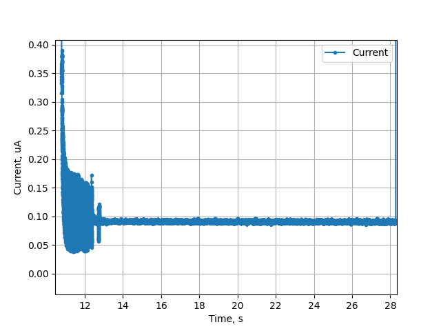
If we zoom way in to the deep sleep section, we see the current is consistently below 95nA, as shown by the images below!
![]()
![]()
In summary, IT WORKS! Nanosleeper achieves a deep sleep with timed wakeup at up to 4095 minute periods while consuming <95nA!
-
Design
01/13/2024 at 21:25 • 0 commentsThe design of Nanosleeper is relatively simple. It is meant to be a development board, so the components on it are meant to represent the minimum for proper operation in the envisioned use case: prototyping ultra-low power systems.
Nanosleeper is also an answer to a question. Ultra-low power systems can commonly achieve <10uA in deep sleep. Getting this down to <1uA is possible, but difficult (even good, modern ultra-low power microcontrollers, RTCs, and voltage regulators can require about 1uA to operate). Nanosleeper takes things another order of magnitude, down to <100nA at 1.8V. At <100nA, Nanosleeper would take >256 years to drain a CR2032 coin cell battery. Of course, the battery will self-discharge much faster than that, but at <100nA the amount of power used in deep sleep can be entirely ignored in battery life calculations (and/or energy harvesting only needs to harvest a very small amount of power).
This log will go through the schematic (PDF available on the project page), and explain why certain decisions were made.
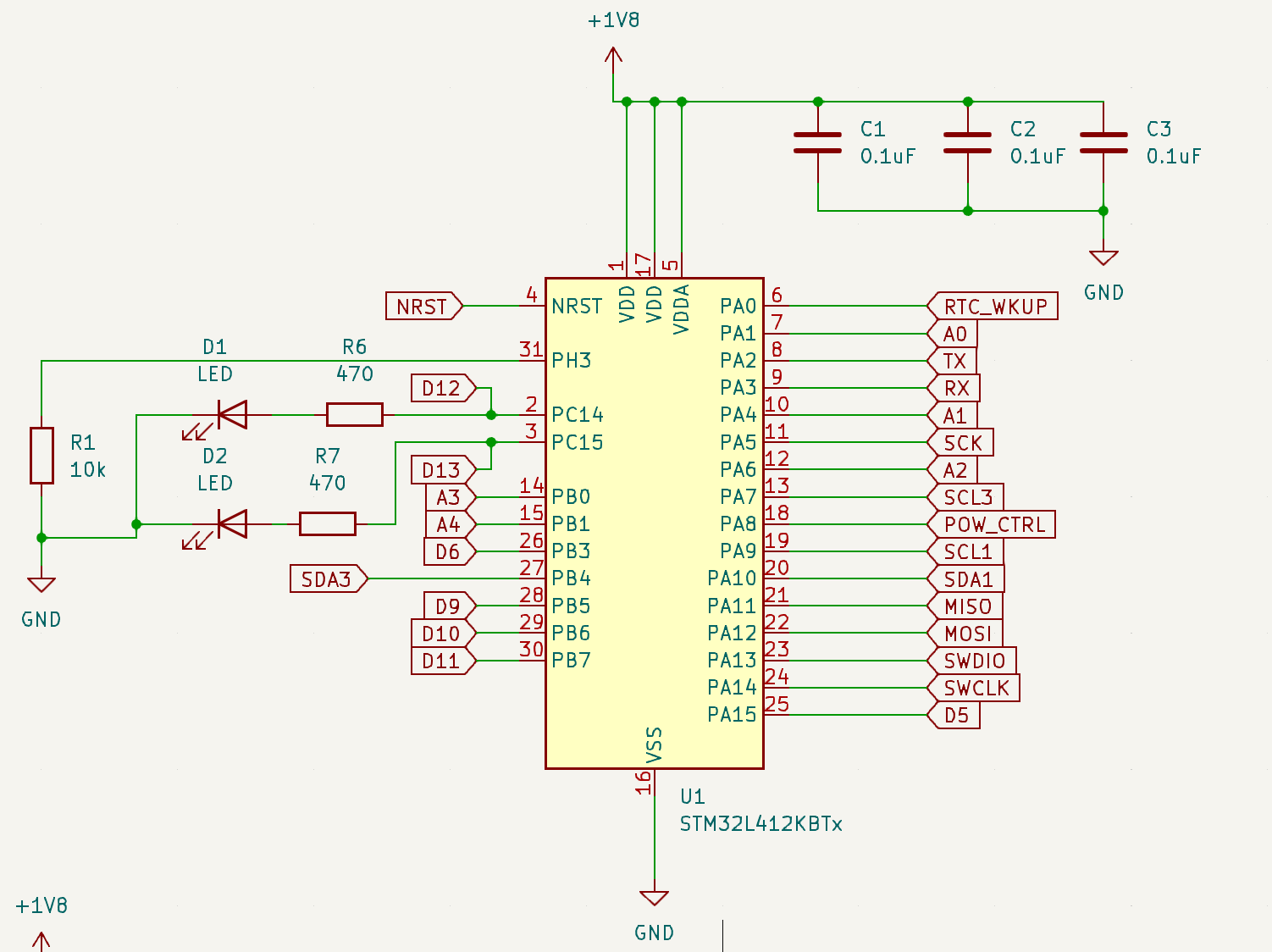
The microcontroller section of Nanosleeper is simple. Decoupling capacitors are included, and a 10kOhm resistor is used to pull down PH3 to ensure Nanosleeper boots properly. Two onboard LEDs are attached to D12 and D13. There is no crystal oscillator attached to the microcontroller since an external RTC is used. Two I2C buses are available. I2C1 is attached to the external RTC and SCL1 and SDA1 are always pulled up to the 1.8V rail. I2C3 is routed to the external pin header, and SCL3 and SDA3 are pulled up to switched power (controlled by the POW_CTRL pin),![]()
The external RTC section is also simple. The RC-3028-C7 RTC module is connected to I2C1, and the INT interrupt output pin is mapped back to a wakeup pin on the microcontroller which can wake it from even the deepest sleep mode (shutdown).
![]()
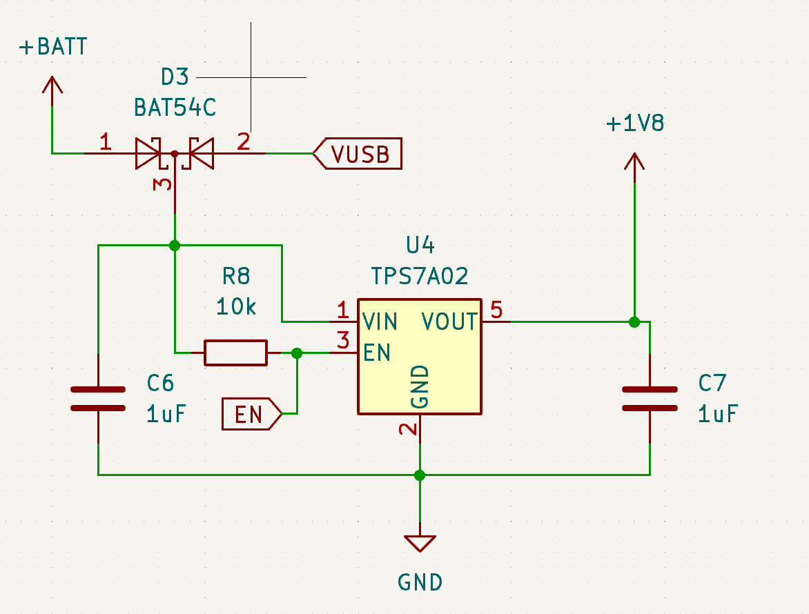
Because the goal of Nanosleeper is to achieve the lowest power performance, it operates at 1.8V. Unfortunately, the STM32L4 cannot run USB at 1.8V, so the USB connector on Nanosleeper has no data abilities. However, the power from USB can be used to power Nanosleeper. A dual diode is used to determine if Nanosleeper operates on battery or USB power. The TPS7A02 voltage regulator supports input voltage up to 6V, so 3V coin cells or rechargeable lithium ion, lithium polymer, or lithium iron phosphate batteries are all acceptable to be used with Nanosleeper
![]()
The least obvious feature of Nanosleeper is its switched power output. External sensors can be connected to the switched power and I2C3, and consume no power at all if Nanosleeper needs to enter deep sleep.
![]()
Nanosleeper - Sub 100nA Sleep Dev Board
A "feather-ish" development board achieving <100nA deep sleep current with real time clock wake-up