 Capt. Flatus O'Flaherty ☠
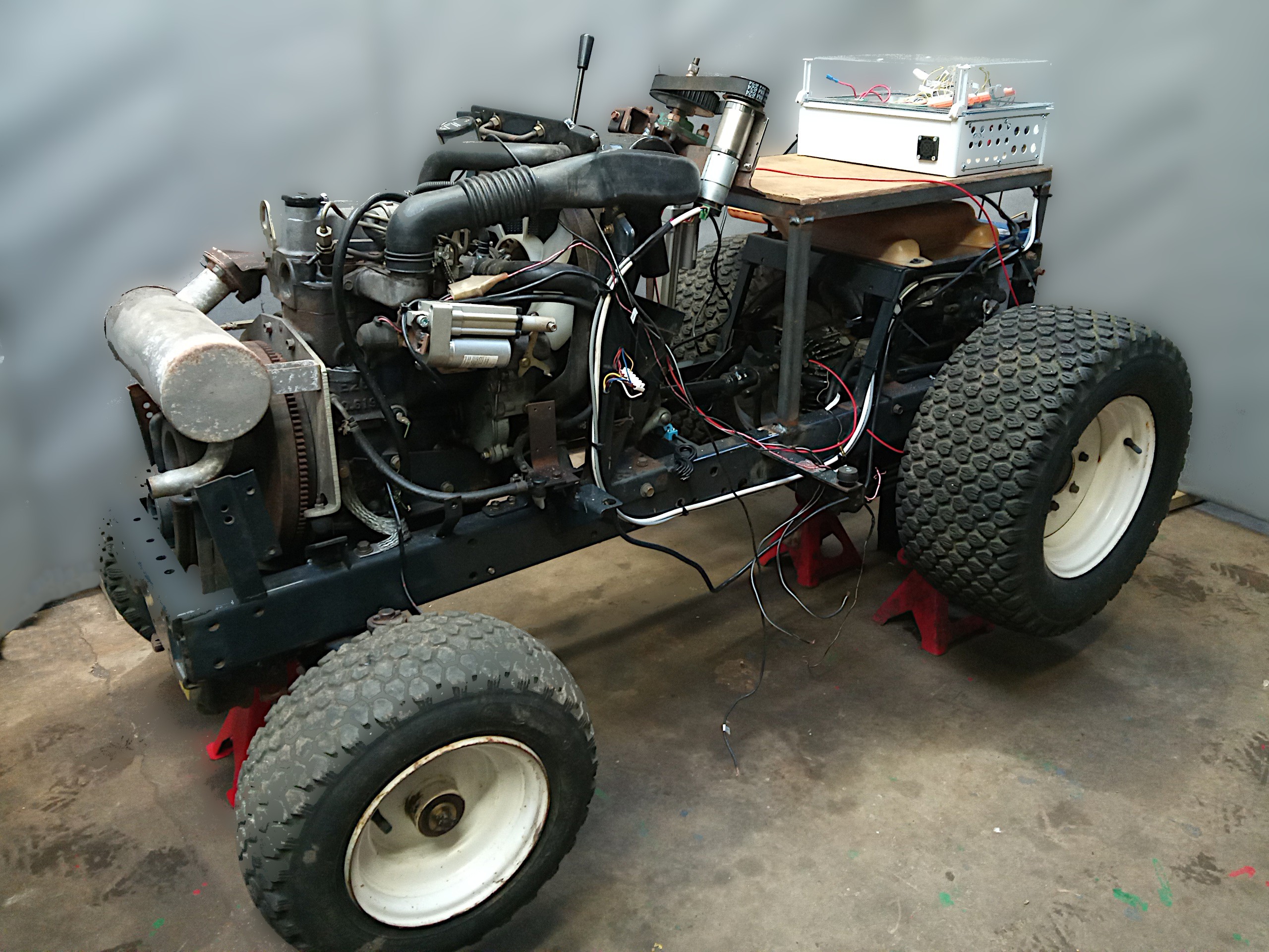
The main systems to enable the machine to drive around on remote control have been installed - steering and the two throttle motors. Yes, this machine has 2 throttles, one to control the engine speed like a normal throttle and another to control the hydrostatic transmission with forwards, reverse and neutral. There are no gears and there is a theoretical infinite range between neutral and 'fast'. In the past we struggled to get fine control and very low speeds and in this version we've installed a 'slow' actuator with a large travel distance (150mm) to get the best out of the in built quadrature encoders. We did tests on the steering with a 300kg spring balance to assess what kind of forces were involved if the wheels were to get stuck in a rut or such like. The balance was attached to the main lever which actuates the Ackerman steering mechanism and we recorded a good 300kg by jamming up the wheels by hand. We maybe should have put an actuator straight onto this lever but instead chose to attach a pulley wheel to the steering column gearbox which would have been a better solution if there was hydraulic assisted steering, of which there is none on the machine. There's a bit of back lash in the gearbox so it will be interesting to see if the machine can still travel in a straight line when using GPS positioning. If it's just too much hassle, we can swap out the pulley wheels and steering column and attach a linear actuator to the main lever instead.
We were worried about burning out the actuator motor by stalling the steering so installed a fuse box and also a custom made circuit board for sensing currents of about 20A which will provide a 'digital fuse' to help prevent damage.
Discussions
Become a Hackaday.io Member
Create an account to leave a comment. Already have an account? Log In.