Close
0%
0%

WEEDINATOR 2025

The WEEDINATOR is back!

Similar projects worth following
The WEEDINATOR is back!
It's been 5 years since the last iteration and there's going to be same major changes.
The mission remains the same: KILL THE WEEDS !!!
..... but rather than build from scratch, we're now using a donor vehicle, an ISEKI SG15, featuring:

• 3 cylinder 15KW diesel engine
• Full hydraulic transmission
• 4 wheel drive
• Front mounted PTO

It's a tiny tractor but easy to work on. The ultimate aim is to provide a flexible control system that will allow others to create their own farm robots.

Sponsored by PCBWay https://www.pcbway.com/

Objectives:

• To provide an open source control system for farm robots on small farms.

Solutions:

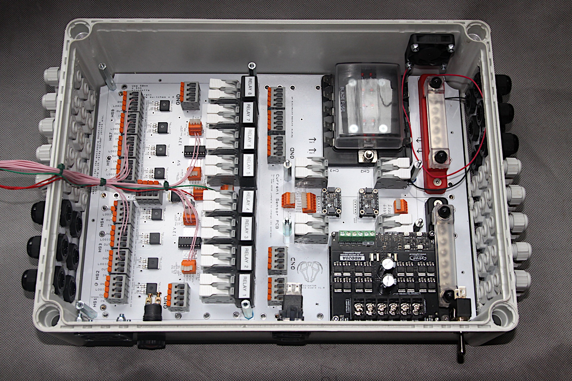
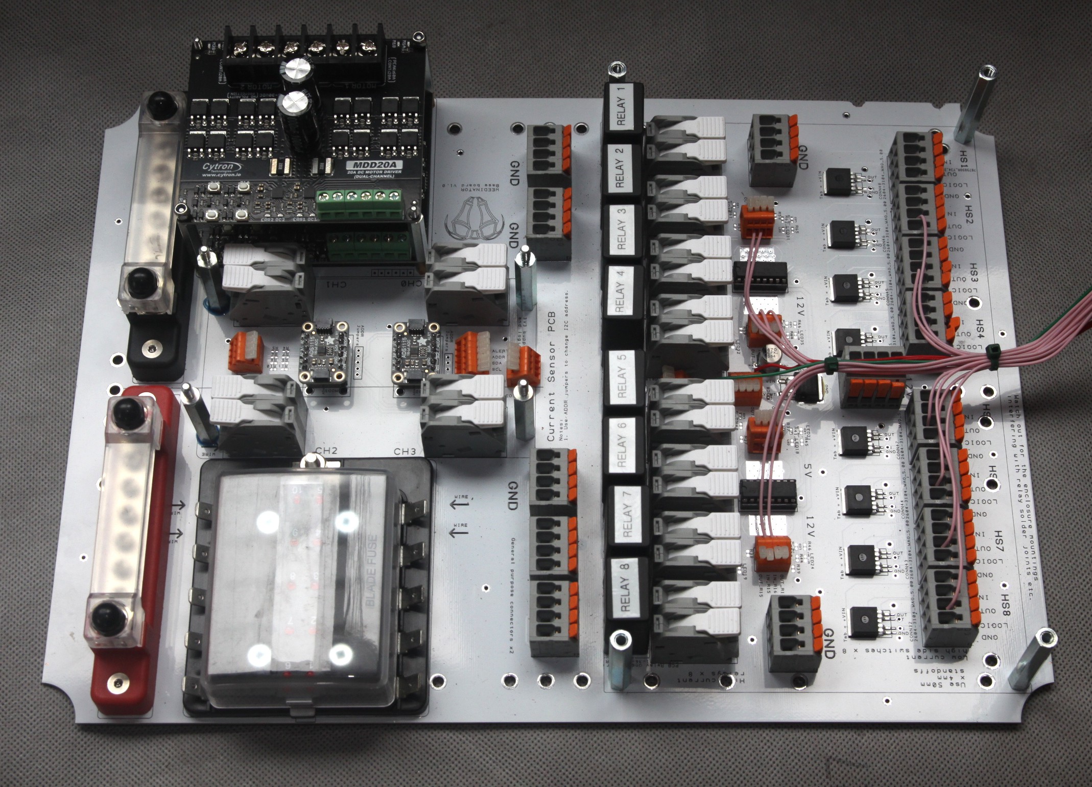
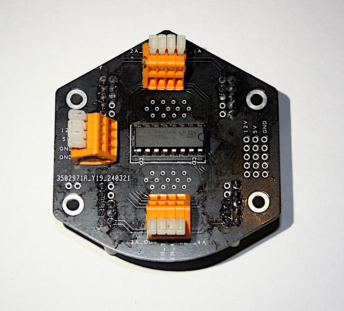
• After many iterations, we decided to make most of the circuits in the control system user configurable, rather than having too many inflexible PCB traces on the PCBs. This has the added advantage that prototyping is easier and faster as otherwise one wrongly routed PCB trace could ruin the whole board. The main MCU is the largest STM Nucleo we could find, with 144 pins, the NUCLEO-H723ZG, and is fully laden with masses of features, including the ability to run at least 3 quadrature encoders (there's probably more available).

• Keep the components as modular as possible so, for example, we use the whole Nucleo plug in board without attempting to solder STM chips on our own boards.

• The PCBs are stackable, so more  NUCLEO-H723ZG modules can be added, for example. The motor controllers are on their own separate PCBs, which are also stackable.

Main Features of Control System:

• Control at least 3 DC motors / linear actuators with in-built quadrature encoders for positioning simultaneously.

• Switch at least 16 40A automotive relays for fuel pump, starter motor, glow plugs, hydraulic cylinder solenoids etc.

• Monitor at least 4 high ampage channels to provide 'digital fuses' and protect motors etc from becoming overloaded.

• Provide at least 10 conventional fuses for motors etc.

• Four x 16 bit Resistor divider circuits for sensing battery voltage, for example.

• Eight boolean Resistor divider circuits for sensing 12V positioning induction sensors, for example.

• Each of the above modules are stackable so, for example, there could be 8 or even 12 digital fuses.
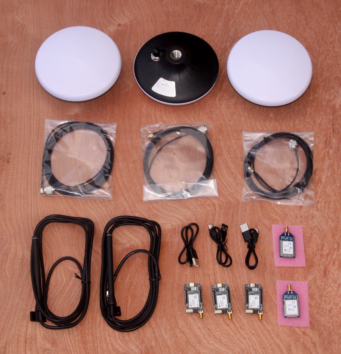
• Cm level GPS.

• 4G modem.

Build Itinerary:

Stage 1:

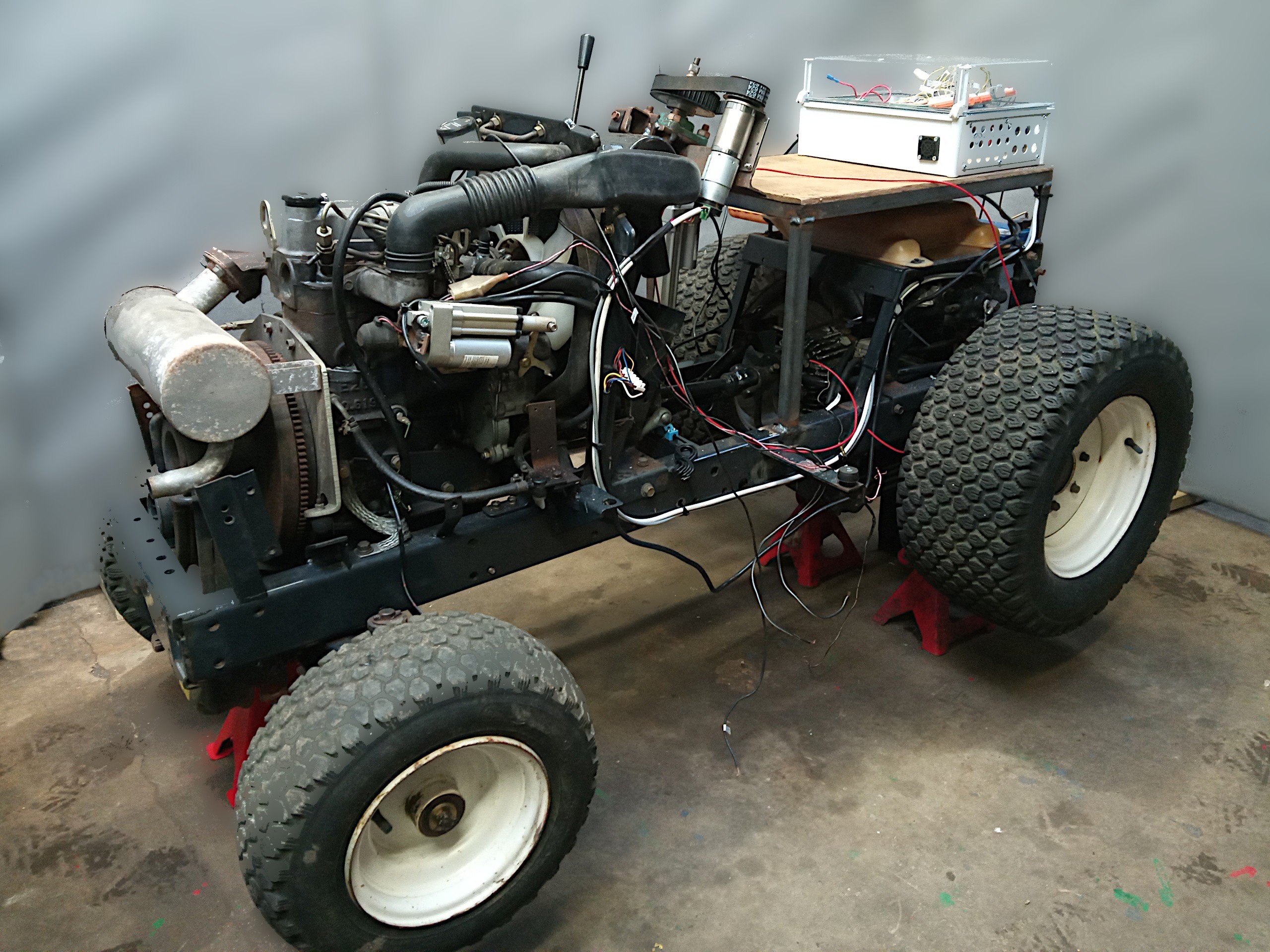
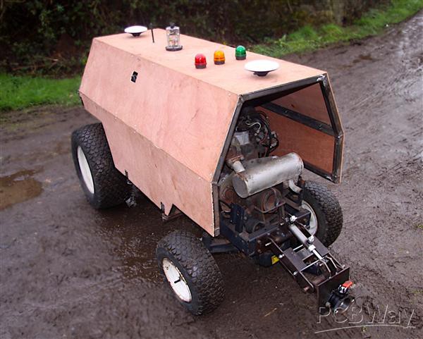
• Make the steering and the throttle radio controlled using the onboard quadrature encoders in the motor and linear actuator in combination with inductive sensors to provide 'homing' locations at the mid point of the steering and the neutral position of the throttle. Since the machine is hydro-static, the throttle moves seamlessly from reverse to forward with a neutral position somewhere in the middle for 'stop' - trying to operate normal manual gears would be much more challenging!

Stage 2:

• Build up a super structure for protecting the internals from the weather and provide mounting points for the various antennae required.

Stage 3:

• Design and build an 'implement' to be positioned on the tractor's 3 point hitch which will have both x and y axis cultivation. The implement probably needs to be shrouded from external sun light to prevent strong shadows interfering with cameras.

Stage 4:

• Add cameras and extra control system for crop position detection to enable y axis cultivation.

IMG_20241119_104325_241.jpg

JPEG Image - 1.55 MB - 11/19/2024 at 11:14

Preview

IMG_20241119_104351_733.jpg

JPEG Image - 1.31 MB - 11/19/2024 at 11:12

Preview

IMG_20241119_104313_046.jpg

JPEG Image - 1.55 MB - 11/19/2024 at 11:12

Preview

IMG_20241119_104400_371.jpg

JPEG Image - 1.58 MB - 11/19/2024 at 11:10

Preview

IMG_20241119_104332_170.jpg

JPEG Image - 1.41 MB - 11/19/2024 at 11:10

Preview

View all 7 files

  • Base Board Laid Into Enclosure

    Capt. Flatus O'Flaherty ☠8 hours ago 0 comments

    Holes for the fan outlet and inlet, alternator lamp, USB connectors and main switch were pre-drilled. There's an option to add a digital volt meter, if there's room on the near side. The fan is placed right over on the top right side as it was thought it was interfering slightly with the MCU serial connections in the previous version of the lay out. All the different sized strain relief grommets are in place, ready to start the heavier wiring. Layers will be wired up one by one and all the high side switches and relays will have connections made to the outside of the box so that the next PCB layer can be installed without having to worry about going backwards to the previous one. It looks tidy at the moment, but adding the wiring will make it much more confusing, if it were not for careful labeling of each wire.

  • New PCB Layer Configuration

    Capt. Flatus O'Flaherty ☠9 hours ago 0 comments

    Large PCBs are expensive, but in this situation it seems to be appropriate to use one to fill the lowest layer of the control box. The new base PCB has a bank of High side switches, relays and a current sensing module are included. Other components such as bus bars, motor drivers modules and fuse box are bolted on. Layers of PCBs can be built up upon the base board such as extra motor drivers, current sensor modules, a large bank of high side switches and/or a large bank of relays.


    The underside of the board has captive four pronged nuts for the bus bars and heavy, solid 2mm copper lugs for connecting the 40 amp relays to their grey Wago connectors.

    The four SMD chips on the right hand side are the current sensors. Liberal amounts of thread lock and pools of epoxy resin are used to help prevent the screws on the underside from coming loose. Some of the wiring is already started - the 3.3V logic - and it's now ready to be permanently installed into the enclosure box and some of the heavier wiring done. The current plan is to try and route a lot of the wiring to the far right hand side so that the main stack of PCBs can hinge on this side in case modifications need to be made. It's the same side as the antennae connections at the very top of the main PCB stack.

  • GPS system completed

    Capt. Flatus O'Flaherty ☠9 hours ago 0 comments

    GPS system, with antennae, has now been installed and tested and the main part of the temporary cladding finished. Just waiting for a 4G antenna to arrive before finishing the radio communications.

  • Maiden Voyage of the WEEDINATOR 2025

    Capt. Flatus O'Flaherty ☠9 hours ago 0 comments

    Now that the ground is frozen, the WEEDINATOR 2025 can be tested without creating a muddy mess. One of the most crucial things was to see if the machine could drive REALLY slowly - and we were pleased with the results. The throttle on the hydraulic swash plate was very accurate but a bit slow to react and the machine drove a lot faster in reverse than forwards, which was a bit strange.

  • BCS implement adapter installation

    Capt. Flatus O'Flaherty ☠9 hours ago 0 comments

    Hydraulically activated parallelogram mechanism with BCS hitch attached for BCS type implements such as the finger mower seen in the video above.

  • GPS Equipment

    Capt. Flatus O'Flaherty ☠01/03/2025 at 20:09 0 comments

    Now that there is a temporary canopy, the GPS antennae can be installed. Here below is a photo of all the GPS stuff from Ardusimple in Barcelona:

    3 survey grade GPS antennae

    3 sets of cables for above

    2 correction data radio antennae

    3 Ublox GPS modules

    2 long range radio transmitters for correction data

  • Radio Reciever Dome

    Capt. Flatus O'Flaherty ☠01/01/2025 at 18:54 0 comments

    The photo above shows the radio receiver for radio control inside it's transparent fuse box dome in a half built state. The contstruction is quite fiddly and consists of 2 pentagon shaped PCBs, the top one being used to starp the reciever module down onto and the lower for some signal LEDs.

    The lower PCB has 4 LED channels as below, red, green, blue and yellow. The four LED clusters are powered by 12 volts via the L293D chip. The chip itself requires 12V for the LED power, 5V for the logic power and can be activated with 3.3V output from the MCU.

    Finished assembly:

  • Cladding the Outside of the Robot

    Capt. Flatus O'Flaherty ☠12/26/2024 at 15:41 0 comments

    A hinging frame was built out of 30mm x 3 box section and temporarily clad with 2mm plywood. The plywood will be replaced with aluminum tread plate sometime in the near future. The whole structure, including the hinge, is mounted on 30mm rubber blocks to try and reduce vibration and get more accurate signals from the GPS antennae, which will be mounted on the top surface. The hinge itself ended up being more complicated than anticipated as an extra rubber mounted was needed in the horizontal plane. The structure is not unduly heavy, but to get easy access to the oil dip stick and engine cooling system, an simple electrical actuator might be a good idea - no need for quadrature encoders - just electrical end stops to prevent high stall currents at each end of travel.

  • Homebrewed PID Algo in Action

    Capt. Flatus O'Flaherty ☠12/08/2024 at 21:15 0 comments

    This video shows our home brewed PID algorithm in action. It runs at about 1/10 th real speed and displays graphs of encoder position, velocity (PWM) and acceleration (deltaPWM). There's some fairly outlandish sound scape generated by slowing down of the motor noise, but keeping the pitch the same.

  • Testing Engine Start/Stop, Glow Plugs, Fuel Pump and Cut Off Solenoid Using Onboard 40A Relays

    Capt. Flatus O'Flaherty ☠12/08/2024 at 20:52 0 comments

View all 16 project logs

Enjoy this project?

Share

Discussions

Does this project spark your interest?

Become a member to follow this project and never miss any updates