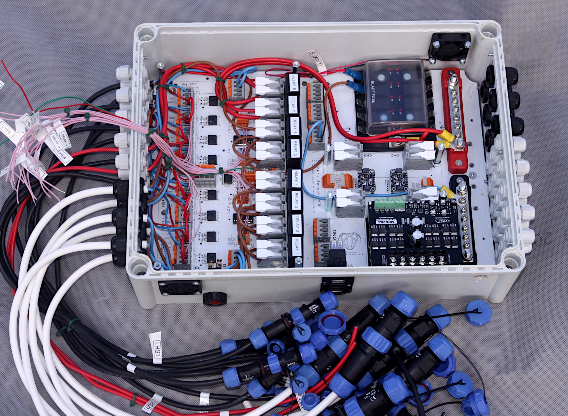
This is the first layer of the system, the Base Layer, featuring 8 x 40 automotive relays, 8 x SMT high side switches, 4 channel 16 bit current sensing, fuse box, bus bars and motor controllers. It's vital to be thinking ahead at this stage to the next 3 layers as we really don't want to have to remove the other layers to get access to this one again in the future. We probably don't need all 8 relays, but they're wired up anyway, with their associated connectors, most of which can be 20 Amp except for the starter motor solenoid and the glow plugs which use 60 Amp Deutch DTHD series ones. There's a lot of connectors! Most vehicles combine circuits into one multi-way connector which is a lot cheaper way of doing things, but not easy to hack and soon degrades into an unfathomable mess, even with good labeling. Many of these connections will drive double acting hydraulic cylinders, each of which needs two connections - one for forwards and the other for reverse, the default 'null' position being positionally locked in place by static hydraulic oil rather than neutral.
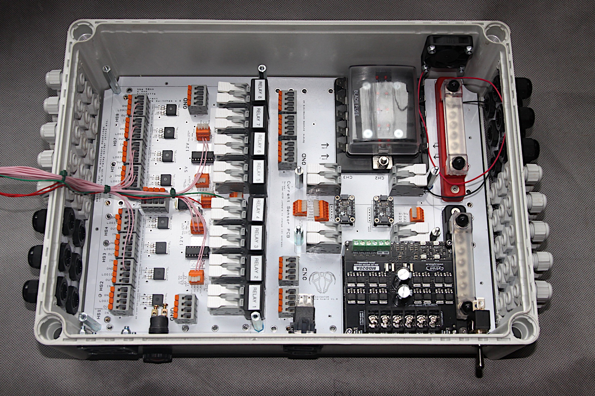
Holes for the fan outlet and inlet, alternator lamp, USB connectors and main switch were pre-drilled. There's an option to add a digital volt meter, if there's room on the near side. The fan is placed right over on the top right side as it was thought it was interfering slightly with the MCU serial connections in the previous version of the lay out. All the different sized strain relief grommets are in place, ready to start the heavier wiring. Layers will be wired up one by one and all the high side switches and relays will have connections made to the outside of the box so that the next PCB layer can be installed without having to worry about going backwards to the previous one. It looks tidy at the moment, but adding the wiring will make it much more confusing, if it were not for careful labeling of each wire.
Large PCBs are expensive, but in this situation it seems to be appropriate to use one to fill the lowest layer of the control box. The new base PCB has a bank of High side switches, relays and a current sensing module are included. Other components such as bus bars, motor drivers modules and fuse box are bolted on. Layers of PCBs can be built up upon the base board such as extra motor drivers, current sensor modules, a large bank of high side switches and/or a large bank of relays.
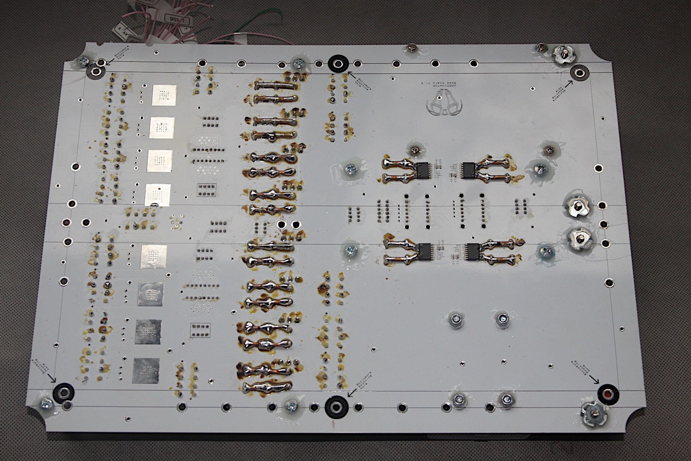
The underside of the board has captive four pronged nuts for the bus bars and heavy, solid 2mm copper lugs for connecting the 40 amp relays to their grey Wago connectors.
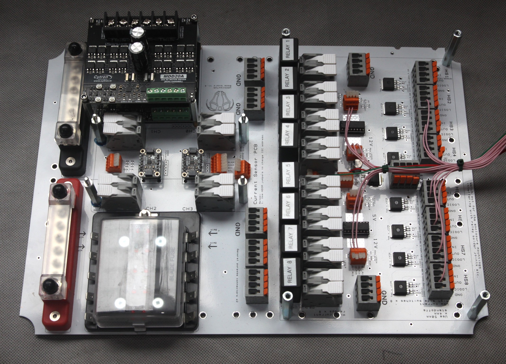
The four SMD chips on the right hand side are the current sensors. Liberal amounts of thread lock and pools of epoxy resin are used to help prevent the screws on the underside from coming loose. Some of the wiring is already started - the 3.3V logic - and it's now ready to be permanently installed into the enclosure box and some of the heavier wiring done. The current plan is to try and route a lot of the wiring to the far right hand side so that the main stack of PCBs can hinge on this side in case modifications need to be made. It's the same side as the antennae connections at the very top of the main PCB stack.
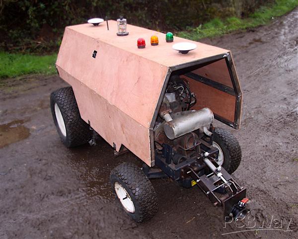
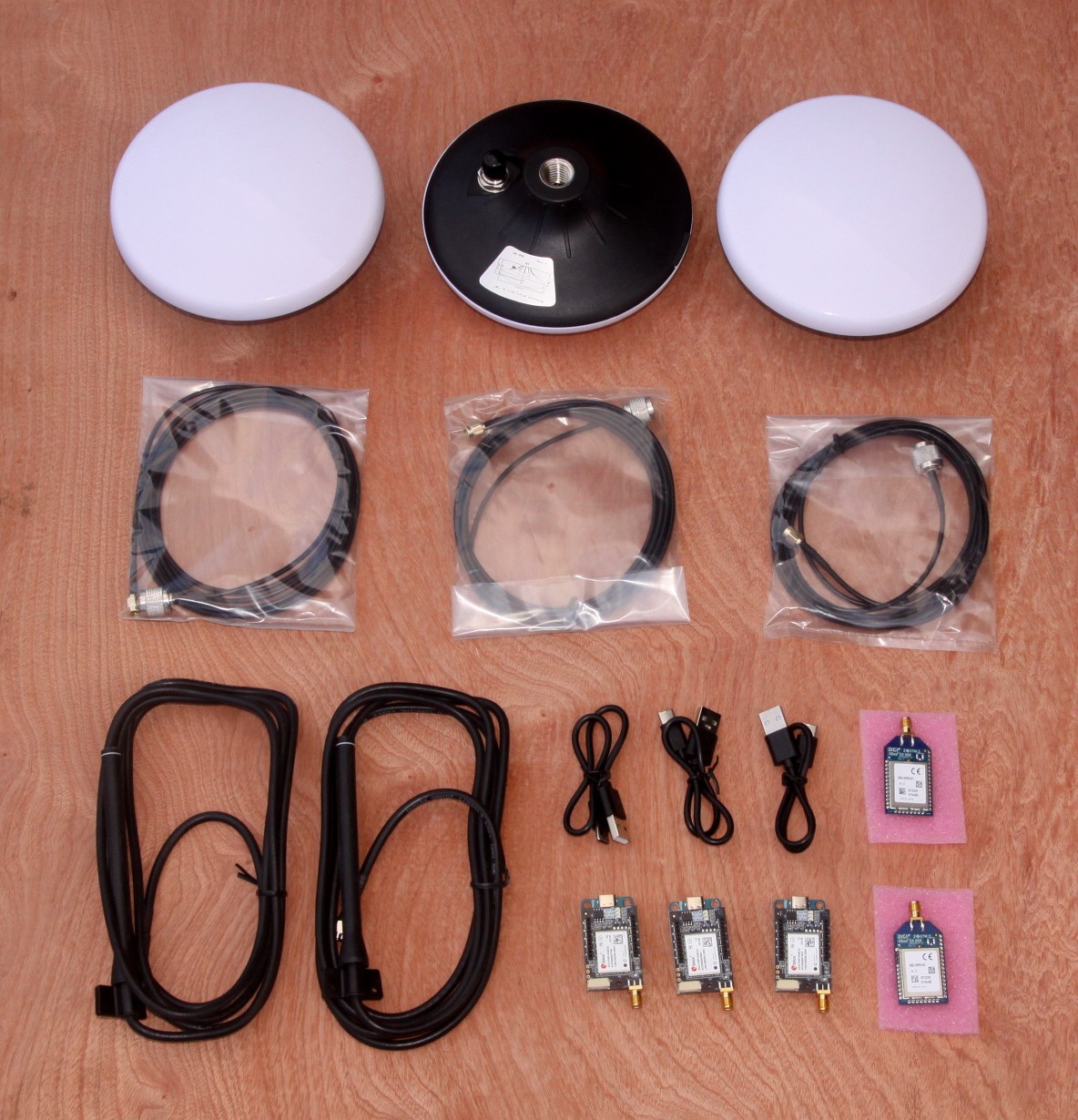
GPS system, with antennae, has now been installed and tested and the main part of the temporary cladding finished. Just waiting for a 4G antenna to arrive before finishing the radio communications.
Now that the ground is frozen, the WEEDINATOR 2025 can be tested without creating a muddy mess. One of the most crucial things was to see if the machine could drive REALLY slowly - and we were pleased with the results. The throttle on the hydraulic swash plate was very accurate but a bit slow to react and the machine drove a lot faster in reverse than forwards, which was a bit strange.
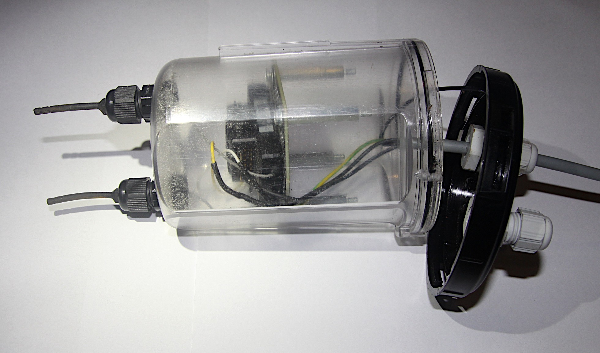
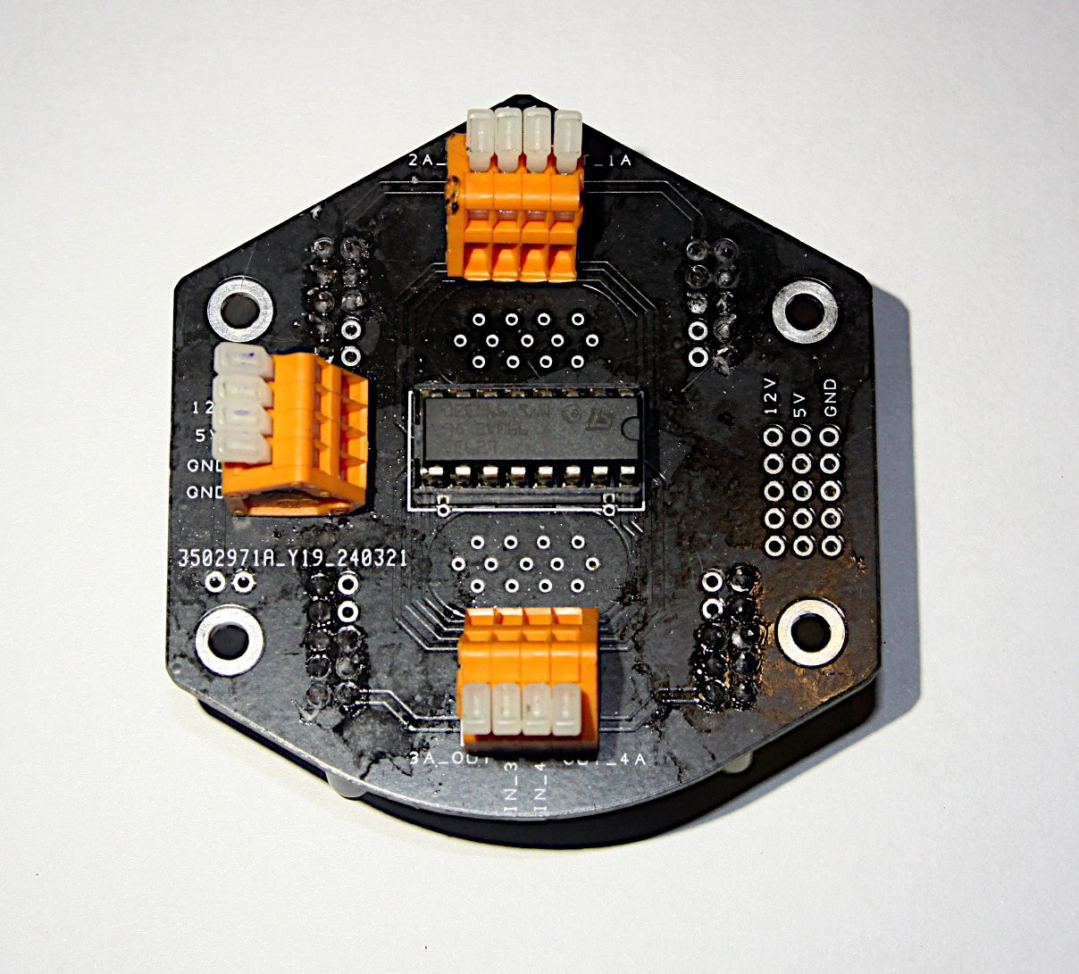
The photo above shows the radio receiver for radio control inside it's transparent fuse box dome in a half built state. The contstruction is quite fiddly and consists of 2 pentagon shaped PCBs, the top one being used to starp the reciever module down onto and the lower for some signal LEDs.
The lower PCB has 4 LED channels as below, red, green, blue and yellow. The four LED clusters are powered by 12 volts via the L293D chip. The chip itself requires 12V for the LED power, 5V for the logic power and can be activated with 3.3V output from the MCU.
A hinging frame was built out of 30mm x 3 box section and temporarily clad with 2mm plywood. The plywood will be replaced with aluminum tread plate sometime in the near future. The whole structure, including the hinge, is mounted on 30mm rubber blocks to try and reduce vibration and get more accurate signals from the GPS antennae, which will be mounted on the top surface. The hinge itself ended up being more complicated than anticipated as an extra rubber mounted was needed in the horizontal plane. The structure is not unduly heavy, but to get easy access to the oil dip stick and engine cooling system, an simple electrical actuator might be a good idea - no need for quadrature encoders - just electrical end stops to prevent high stall currents at each end of travel.
 GOAT INDUSTRIES