 Capt. Flatus O'Flaherty ☠
Featuring 4 channels of 16 bit 15A current sensing and 4 channels of 16 bit voltage sensing via voltage divider, this gadget can act as a digital fuse, protecting the motor driver and actuator from damage due to stalling. The steering actuator is particularly prone to this problem, even though it has an induction sensor at the mid position to reset encoder values - it's just too easy during development and commissioning of the machine to make a small mistake and blow up £200 worth of equipment. The resistor bridge can be used for accurately sensing battery voltage and anything else that crops up in the future.
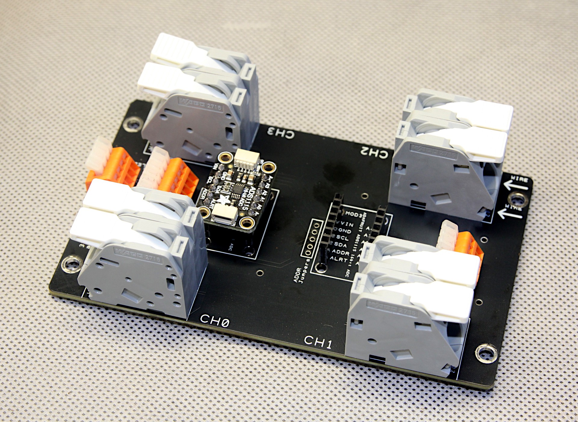
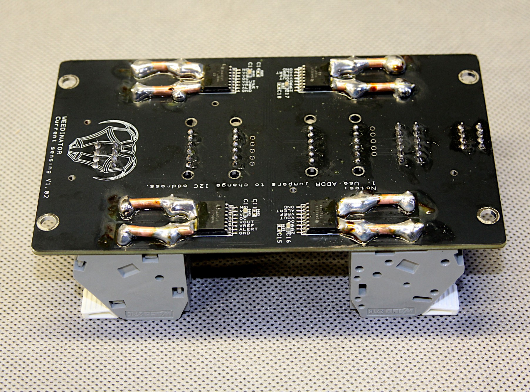
The underside of the board has some heavy duty copper lugs soldered in to connect the current sensing TMCS1123 chips to the large Wago connectors. PCBWay could have supplied extremely heavy 8oz boards, but I chose this option to save cash. BTW, the boards from PCBWay are great quality and the service is superb. They also check with me on the more esoteric features of the board before sending to the press, which guarantees there are no mistakes in interpreting the Gerber files. The chips themselves come in various sensitivity ratings and the ones currently installed are good for +-15A on a 3V3 power supply. The maximum range seems to be +-92 A with the TMCS1123A1A.
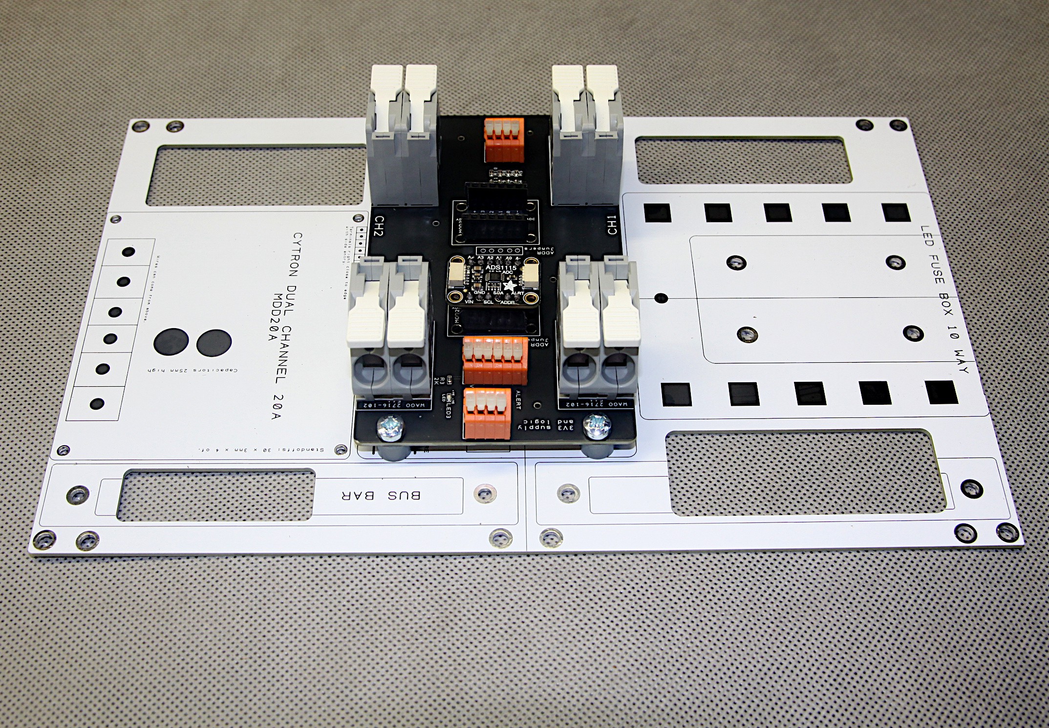
This current sensor PCB sits on top of another PCB that has no electrical connections, just accurately placed mounting holes for 3 main modules - the current sensor, an analogue fuse box and a stack of motor controllers. The large white PCB can also be stacked up and there are large holes in the redundant space for cable routing. Mounting of the 3 modules has been checked and everything fits perfectly and the whole thing fits well in the main enclosure box with all the connections in sensible places. Phew !!
Discussions
Become a Hackaday.io Member
Create an account to leave a comment. Already have an account? Log In.