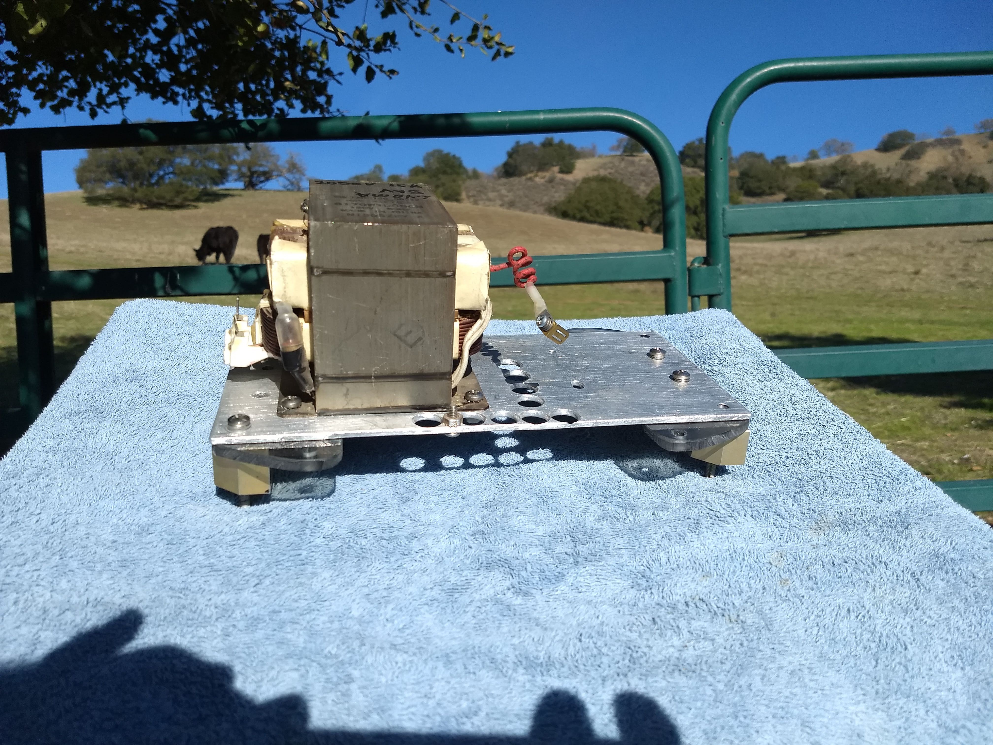
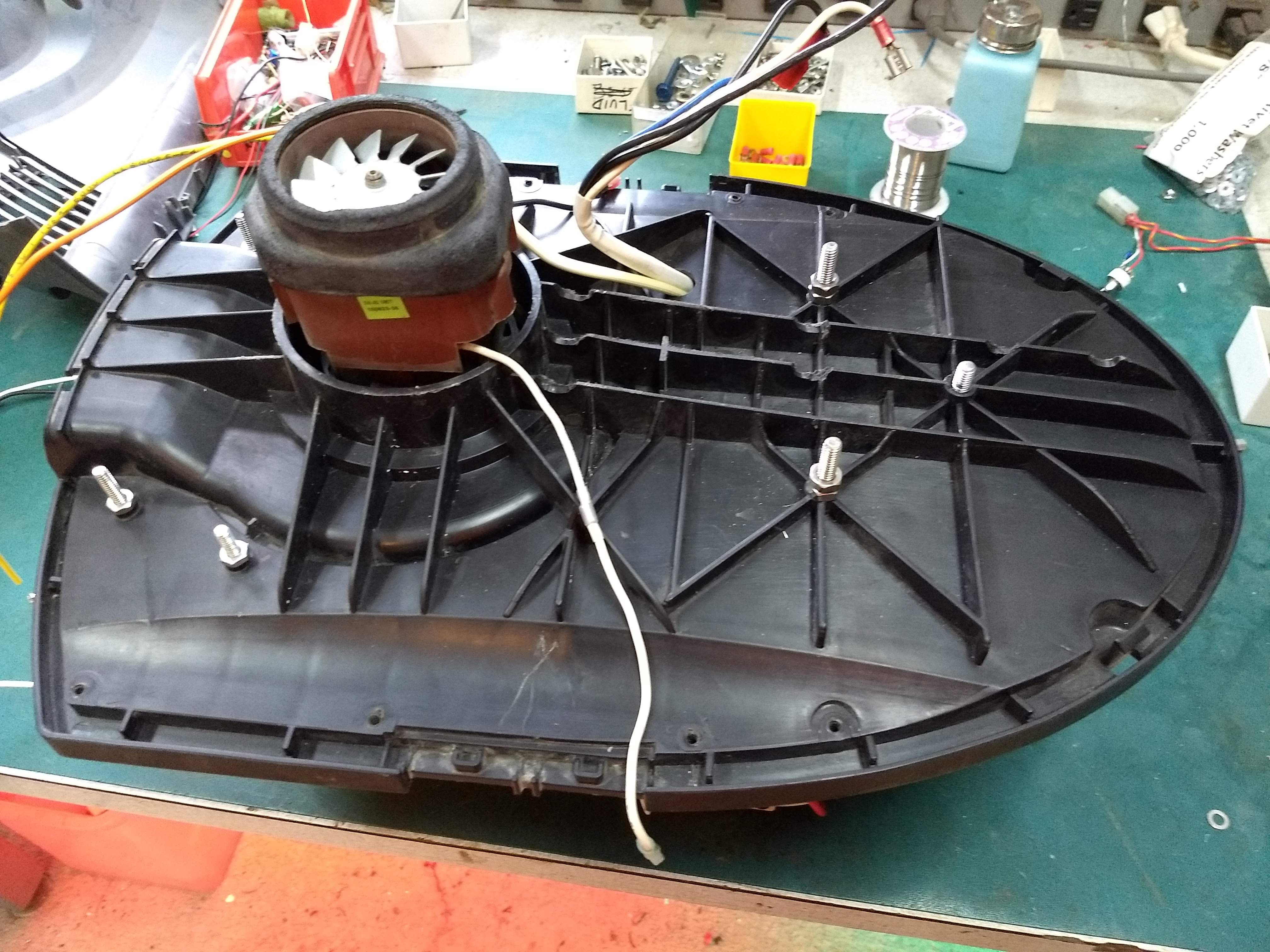
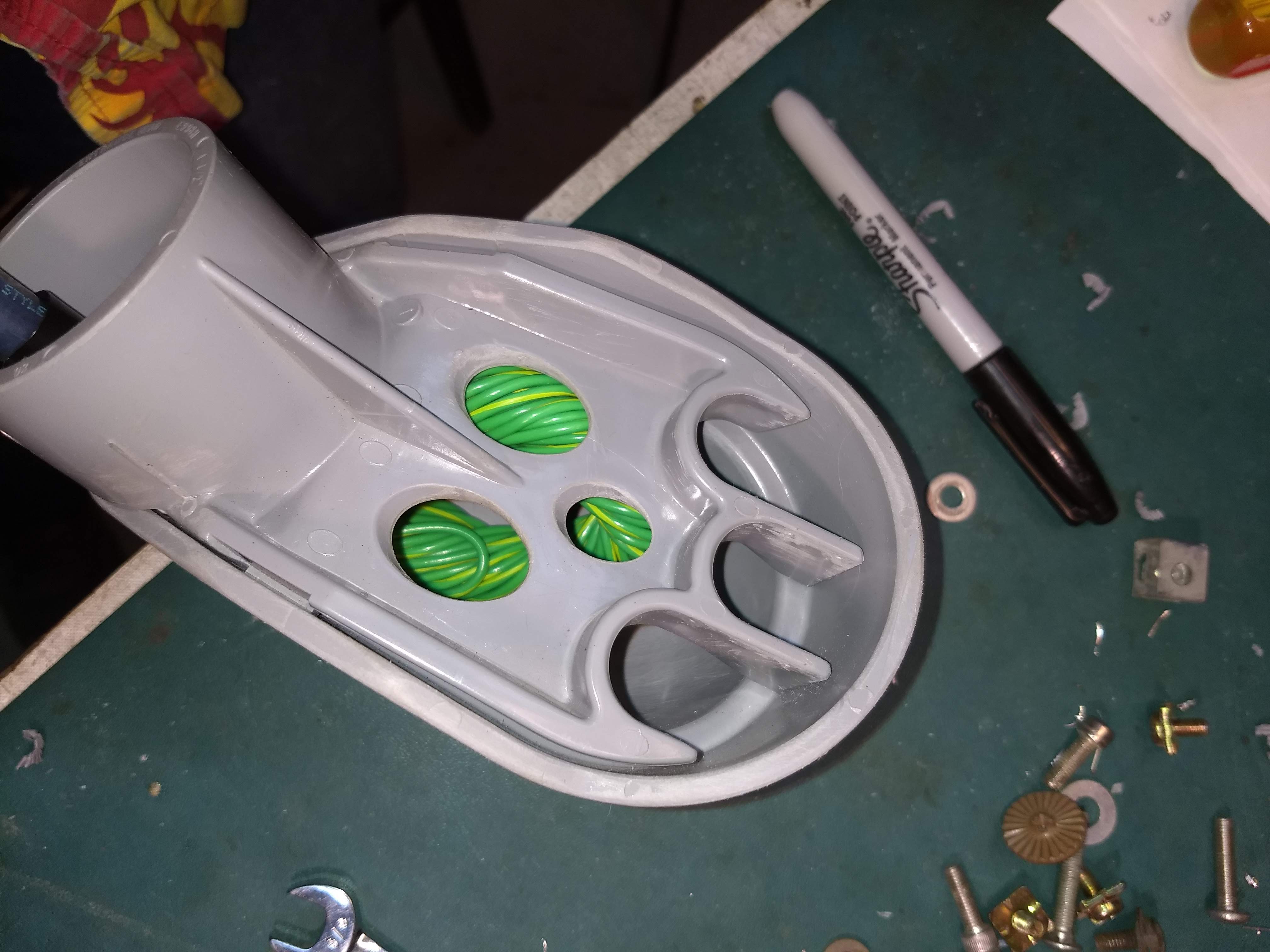
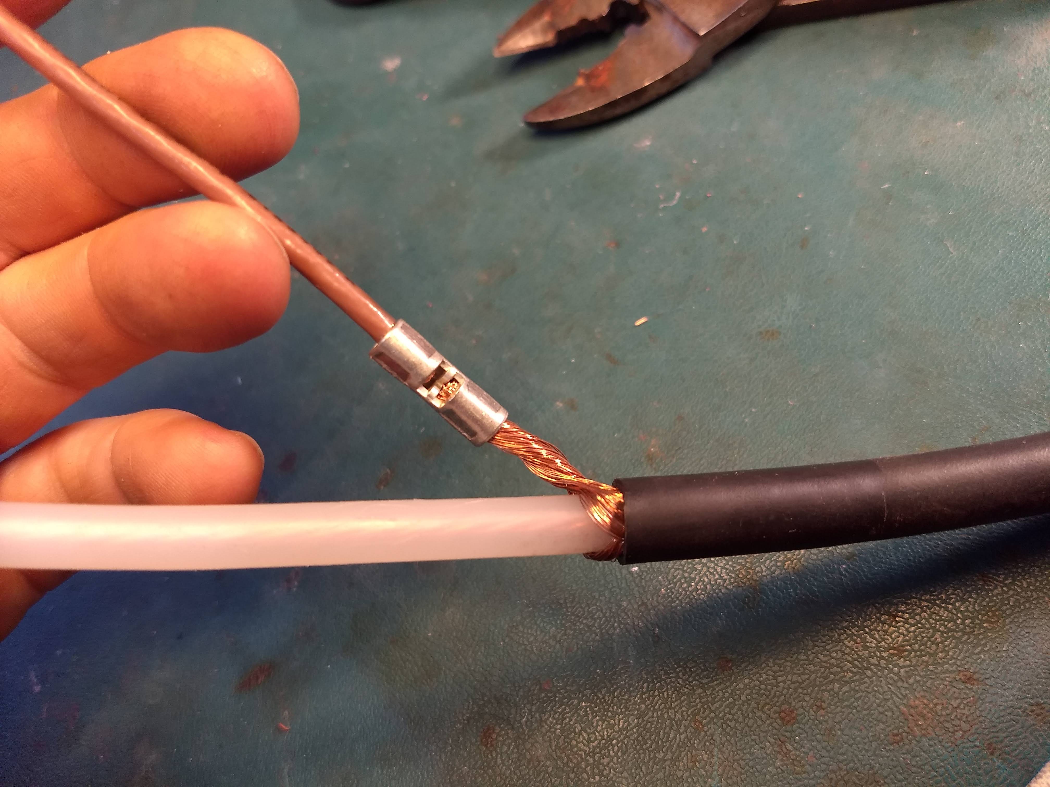
I cleared out thru-holes in this plastic bulkhead, for the baseplate to mount onto. I removed the filter basket, and sanded the snout off the blower inlet. Initially my threaded studs hung up in the holes, making assembly and disassembly difficult. So I spun the studs in a drill, and sanded the center portions smooth. I also reamed out the through holes slightly with a tapered reamer. Another thru-hole was drilled, to bring wires down from the control plate. This hole was sized to pass a four-pin square Molex connector.
4
Assemble Switch Deck
a
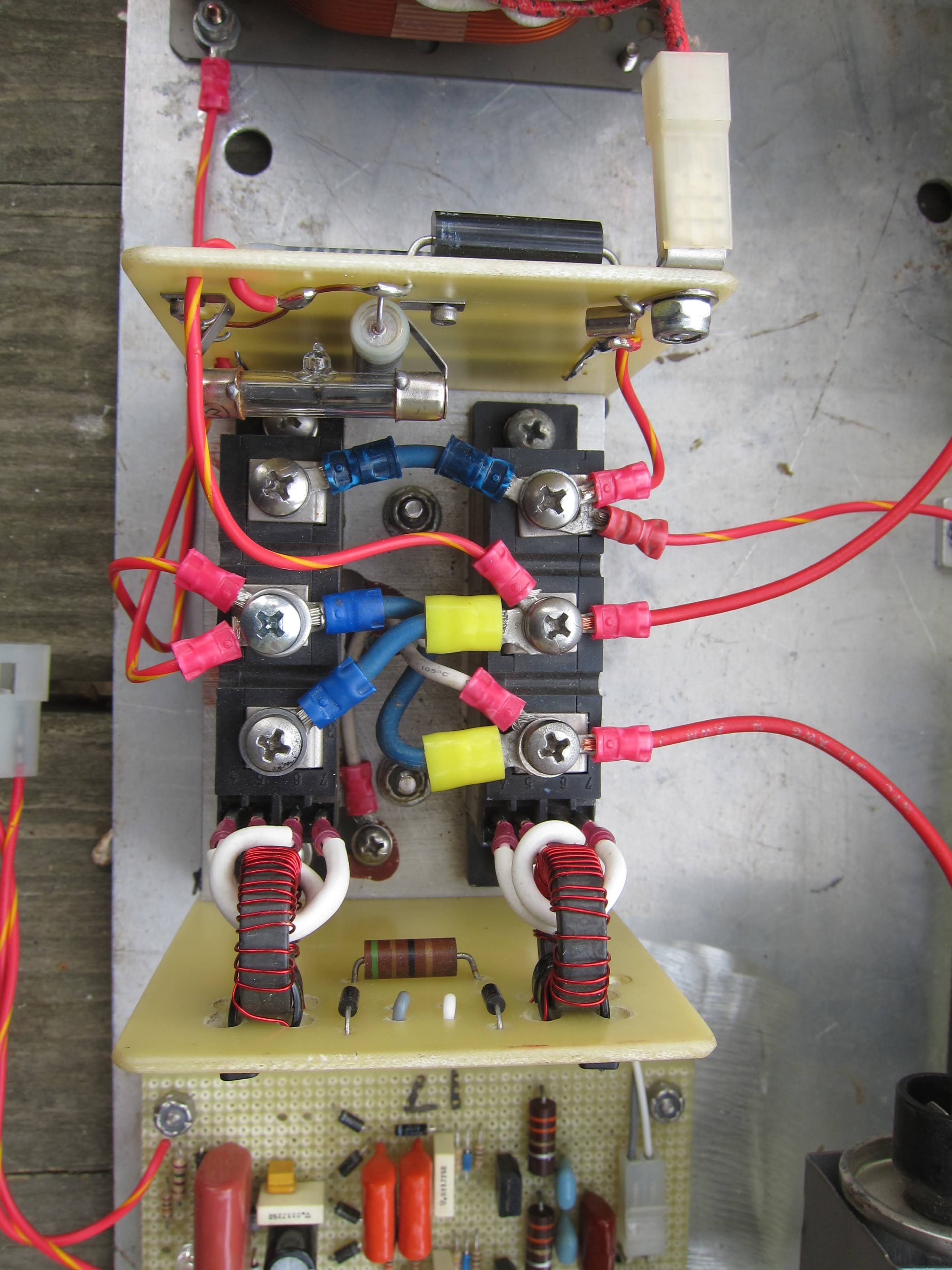
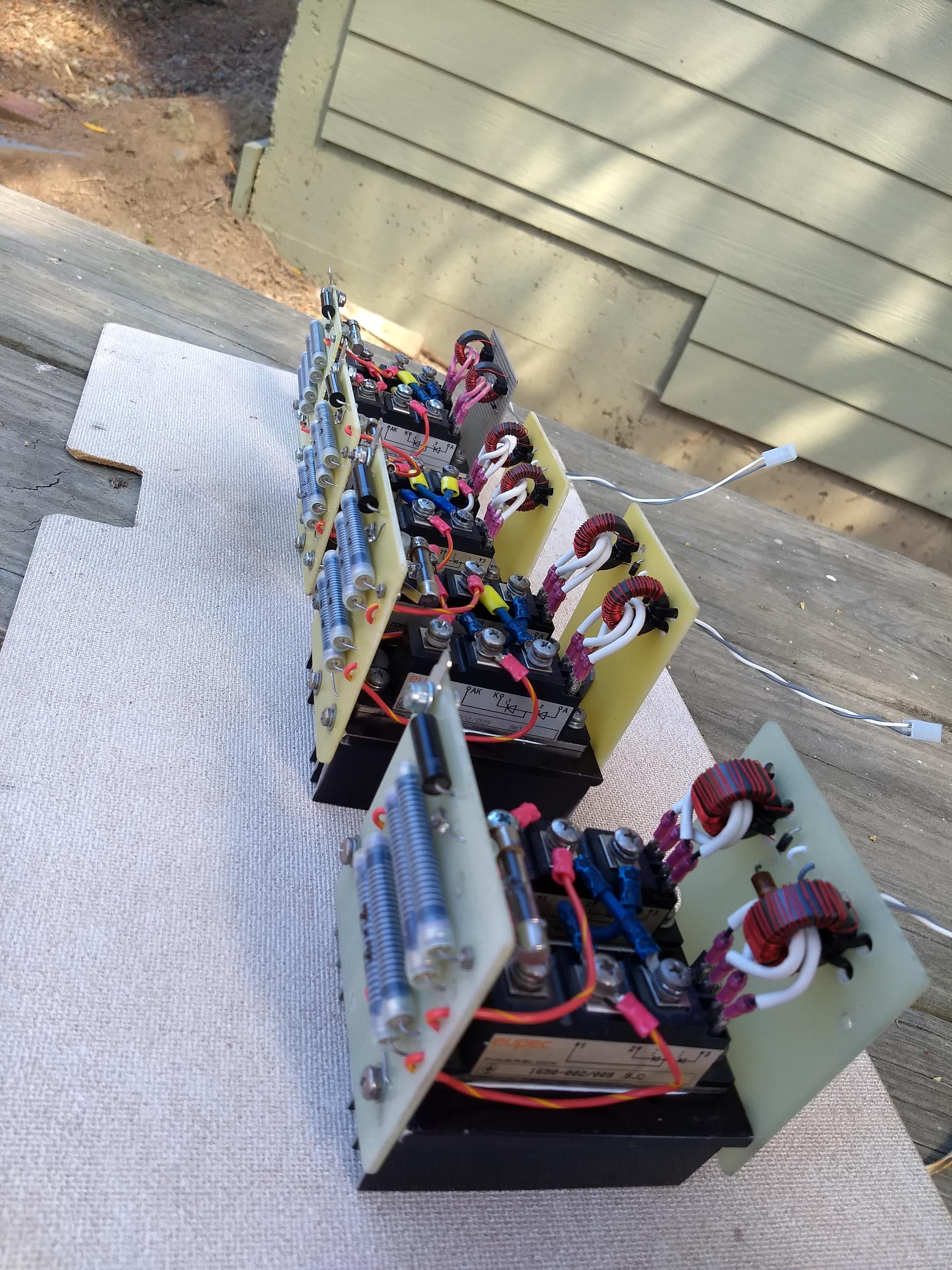
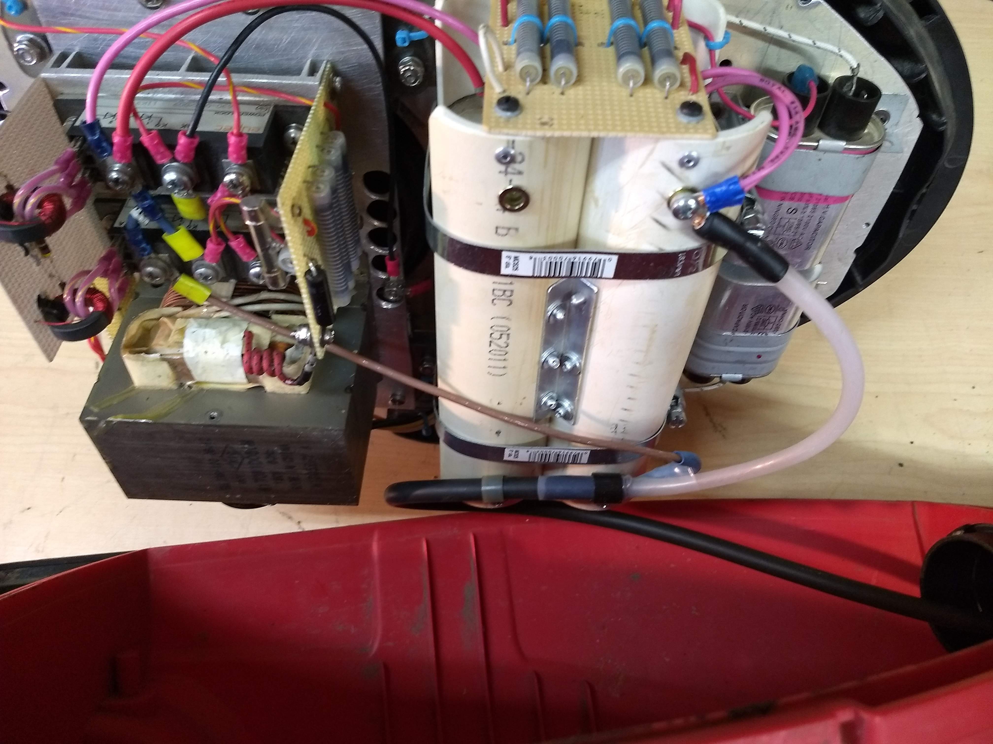
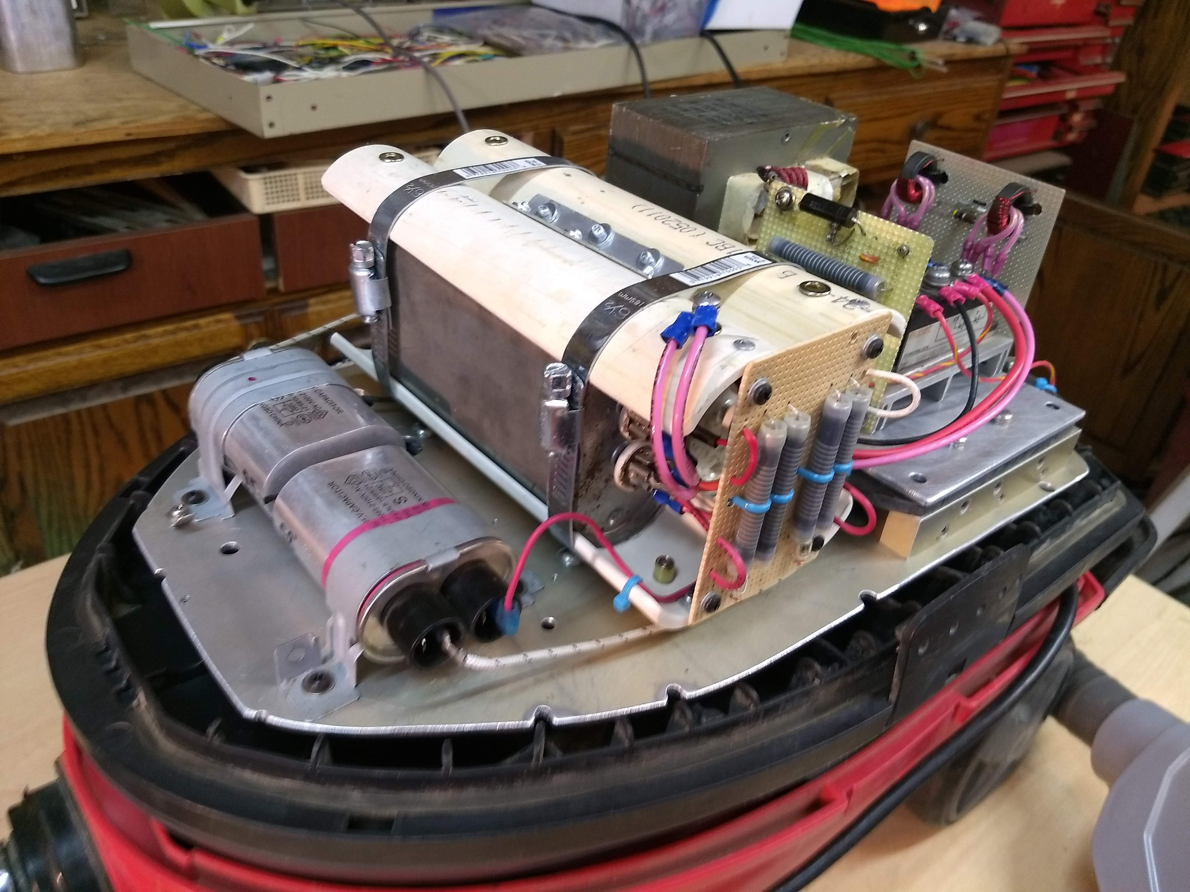
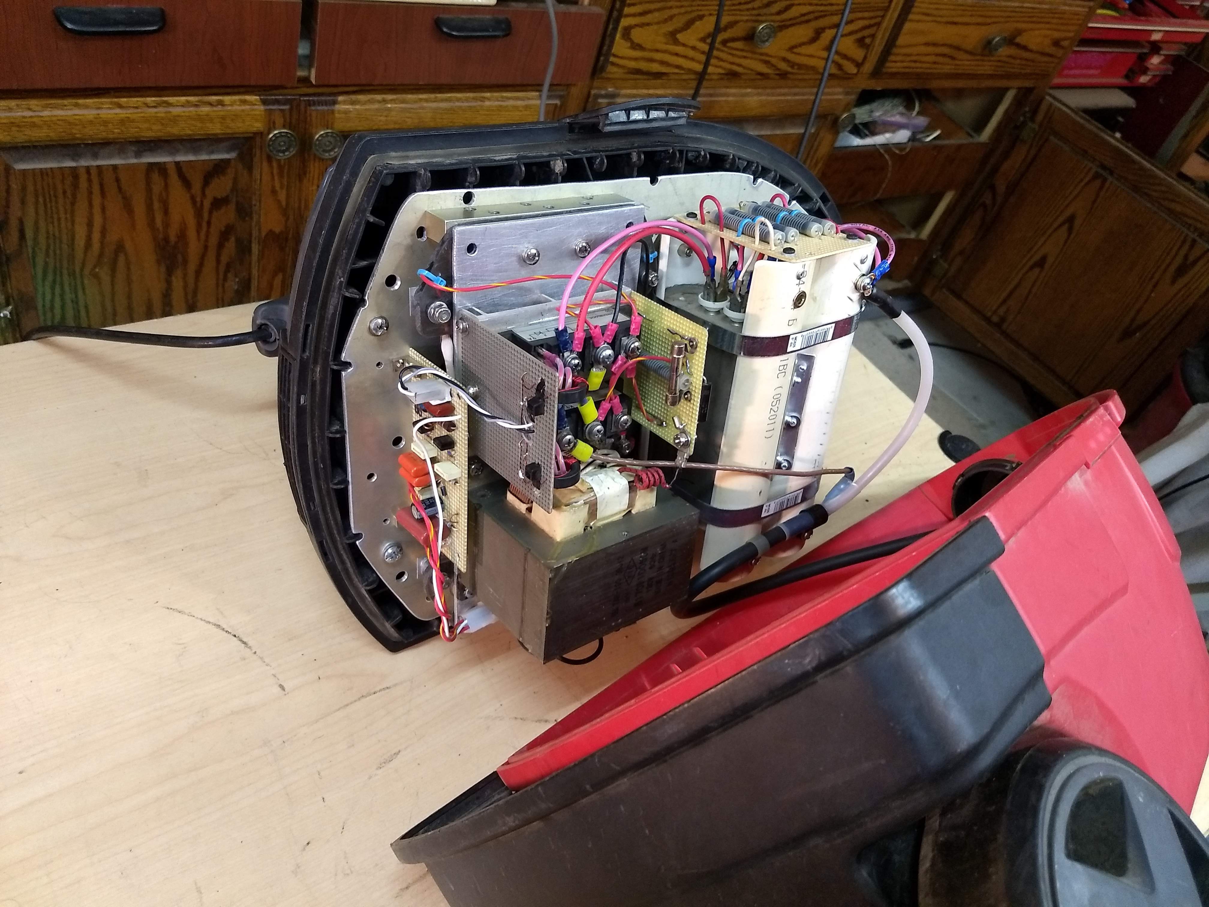
Fabricate Gate Drive and Bleeder/Rectifier Boards. (See schematic.) Mount them onto the heatsink. Mount the SCR Brick Modules. Wire the assembly as shown. (This switch deck is mounted in TMS Unit #5, so it looks a little different.) I used an odd neon bulb shaped like a glass fuse. That was difficult to mount. Any other neon bulb would work just as well (NE-2), as long as it is secured firmly. Notice the SCR Gate Drive wires are insulated with Fiberglass-Silicone sleeving. Physical spacing afforded by the sleeving makes voltage breakdown highly unlikely, at 2,700 volts peak.
5
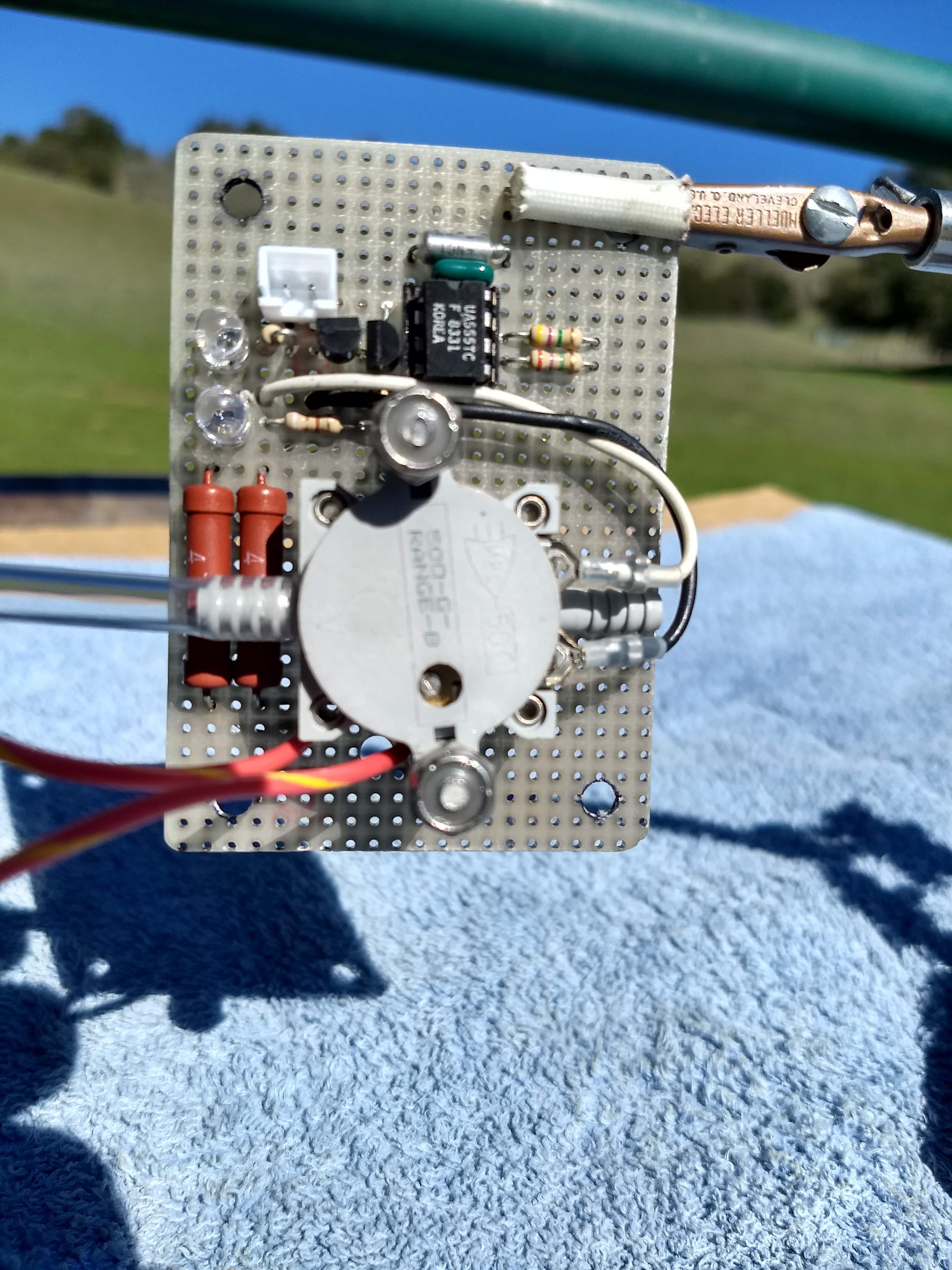
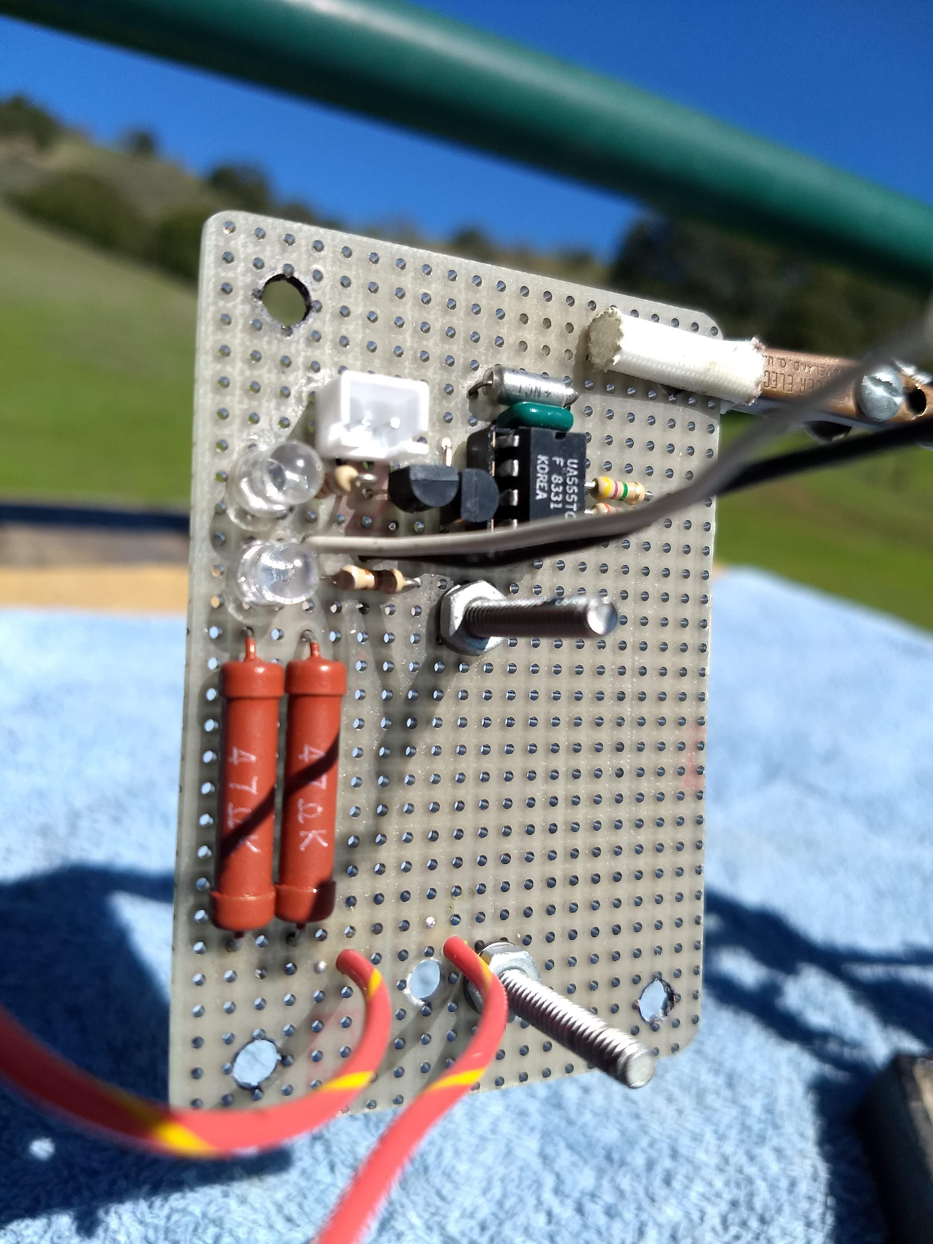
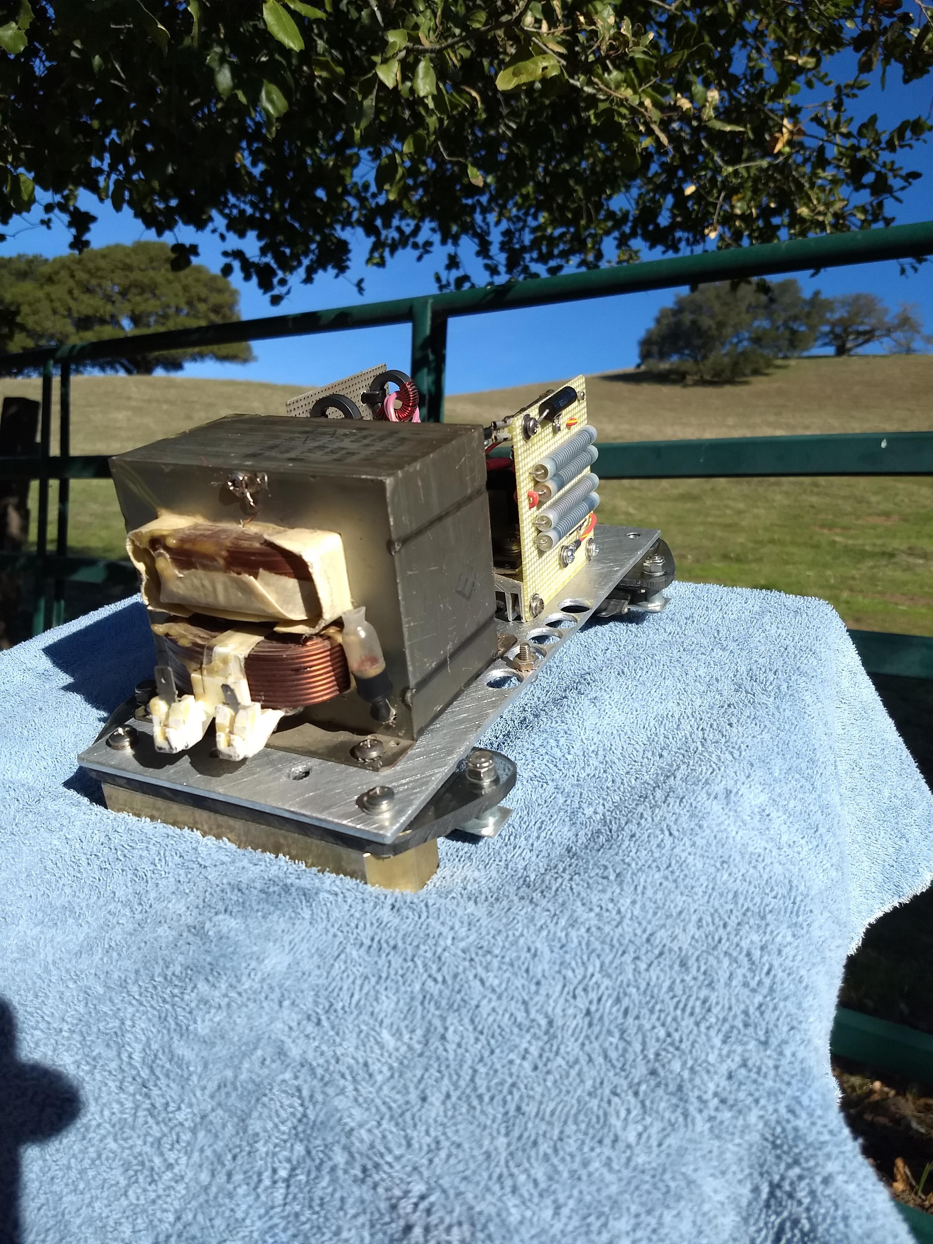
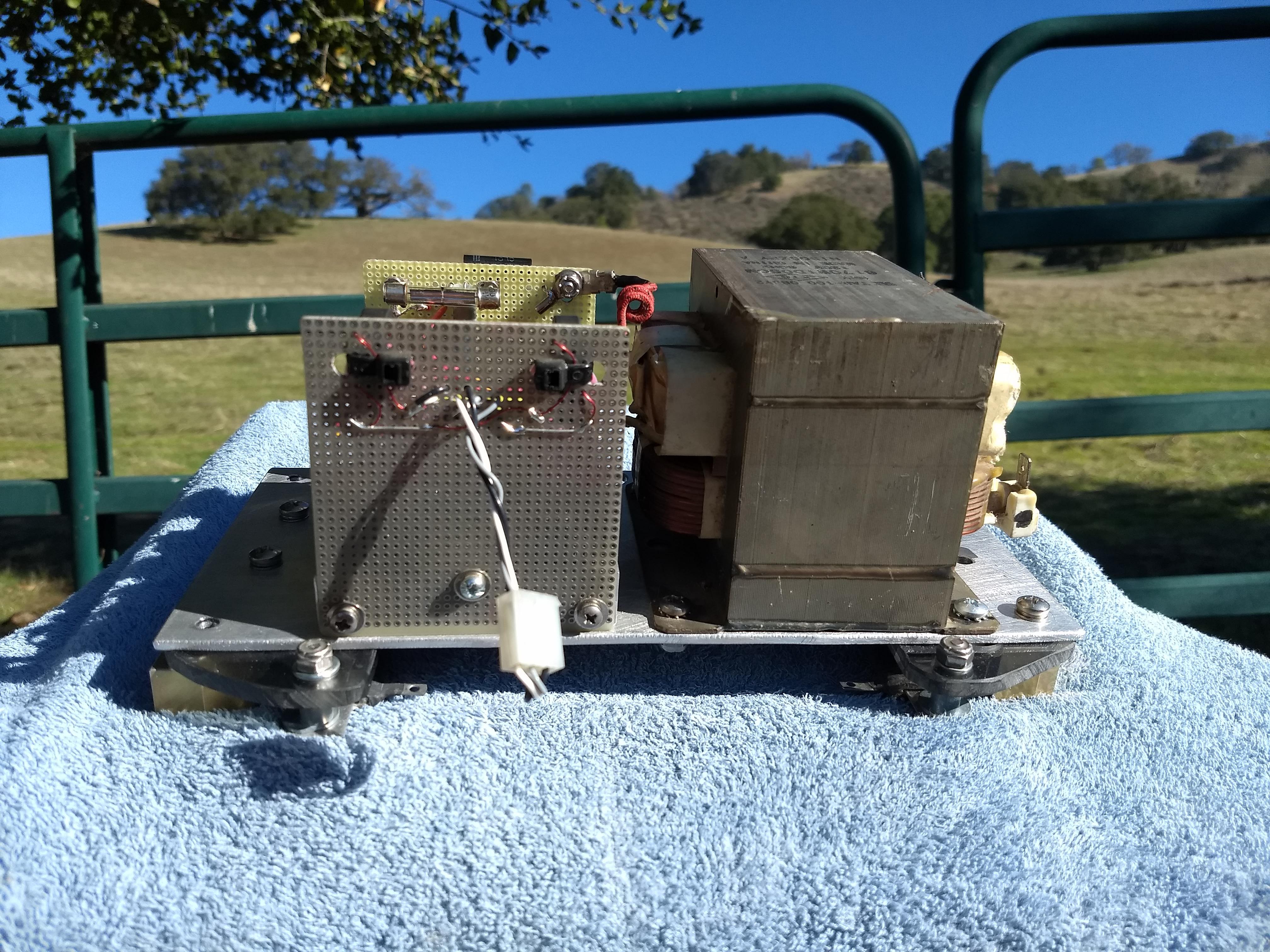
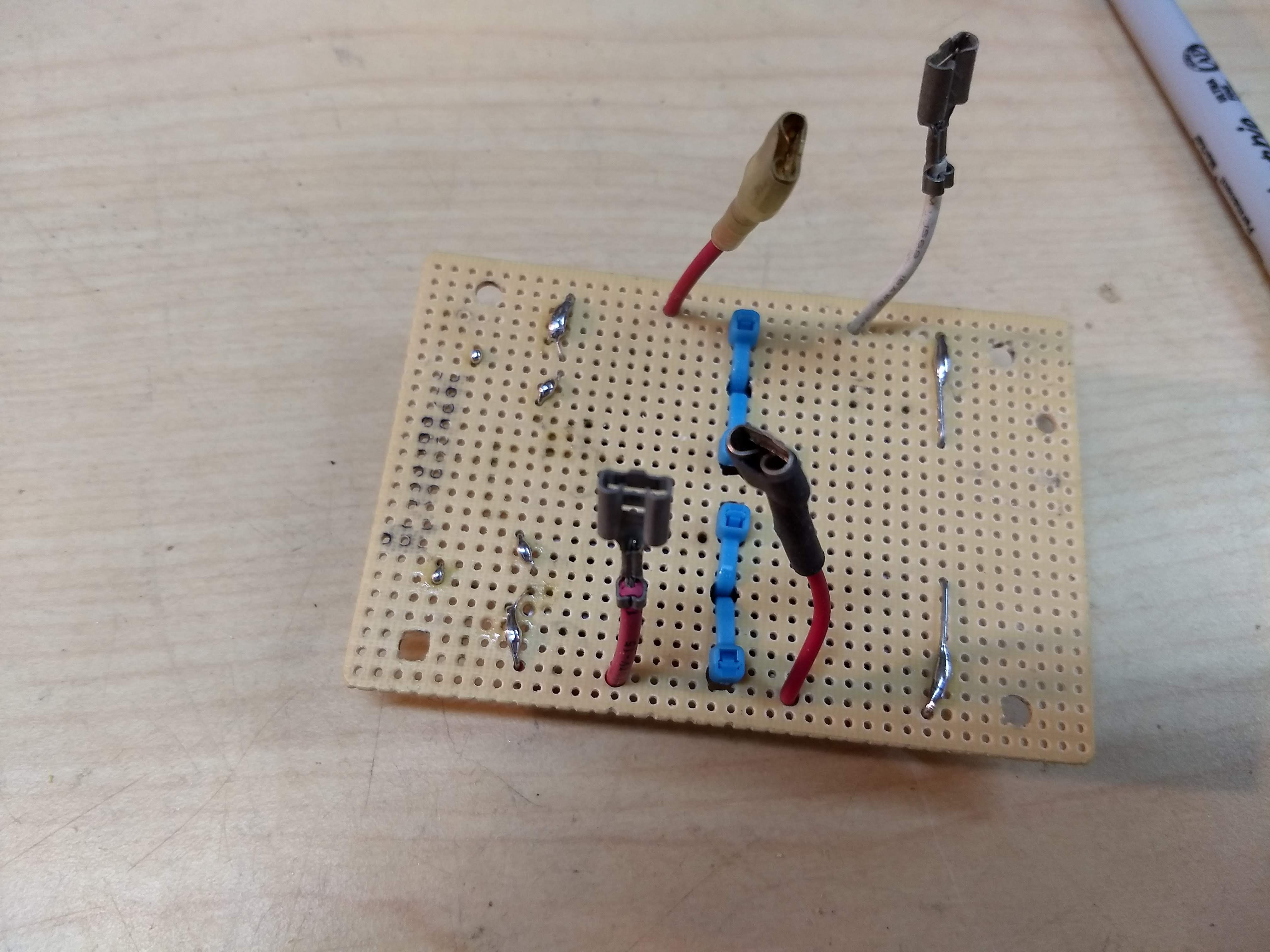
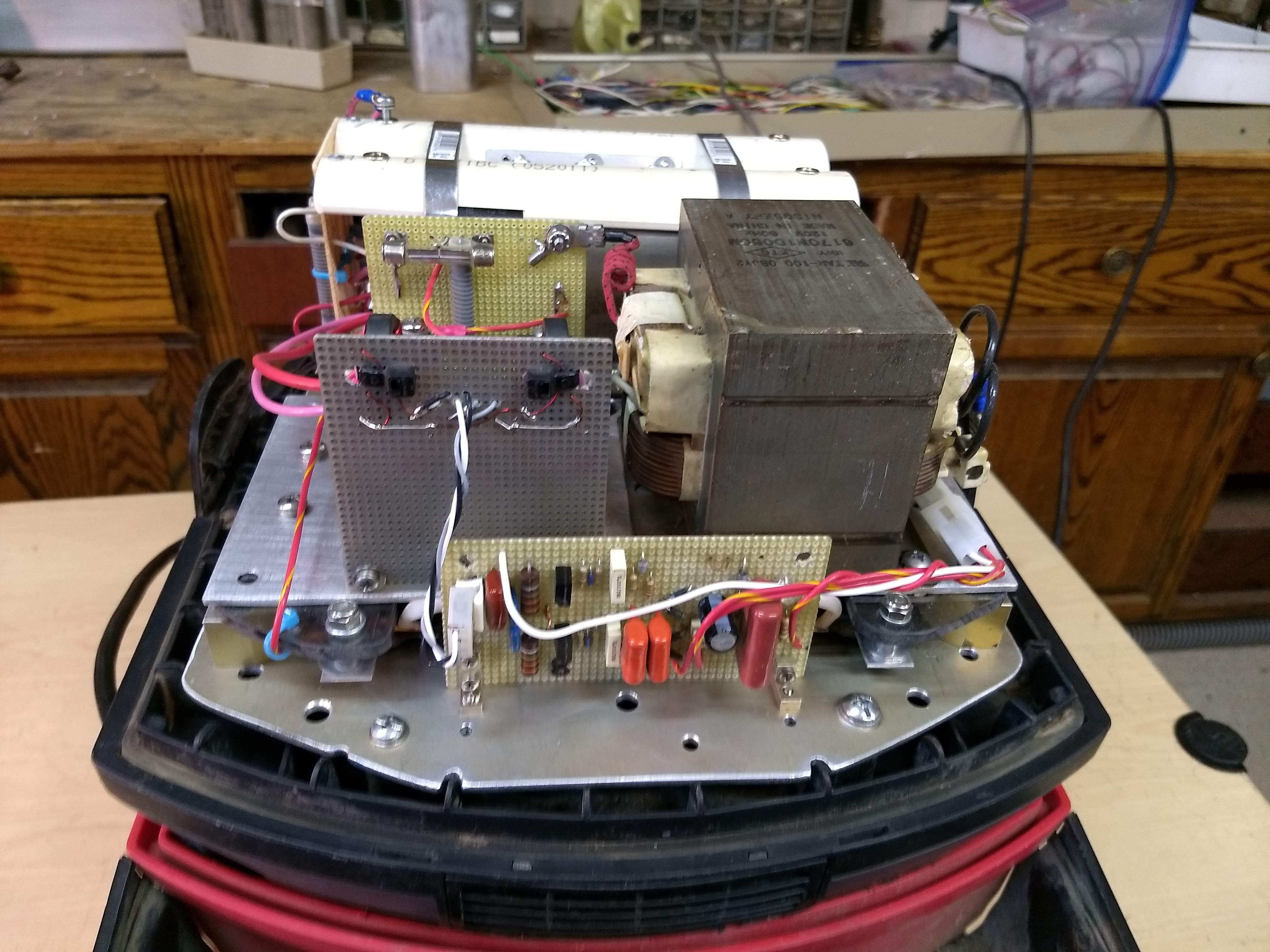
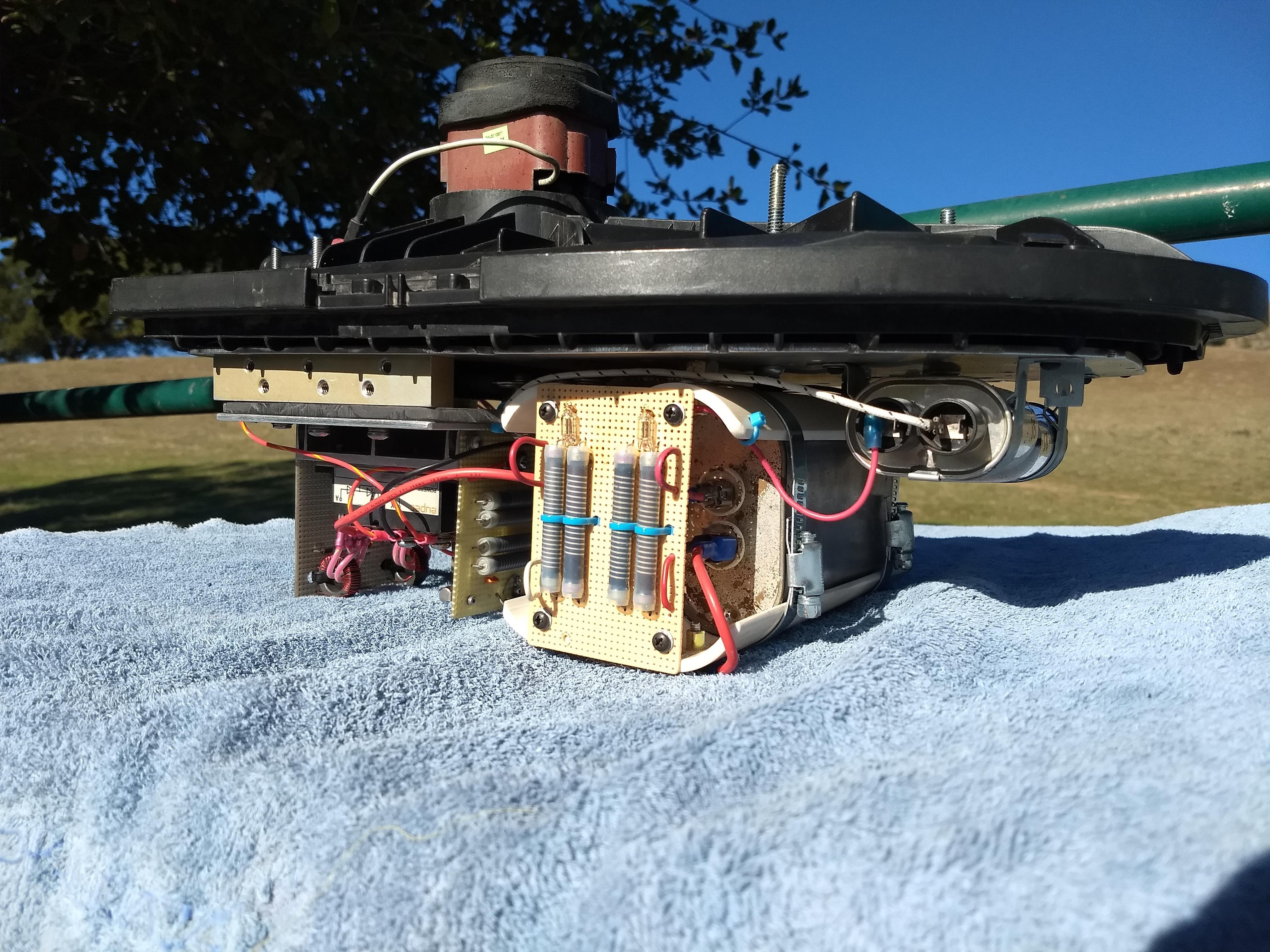
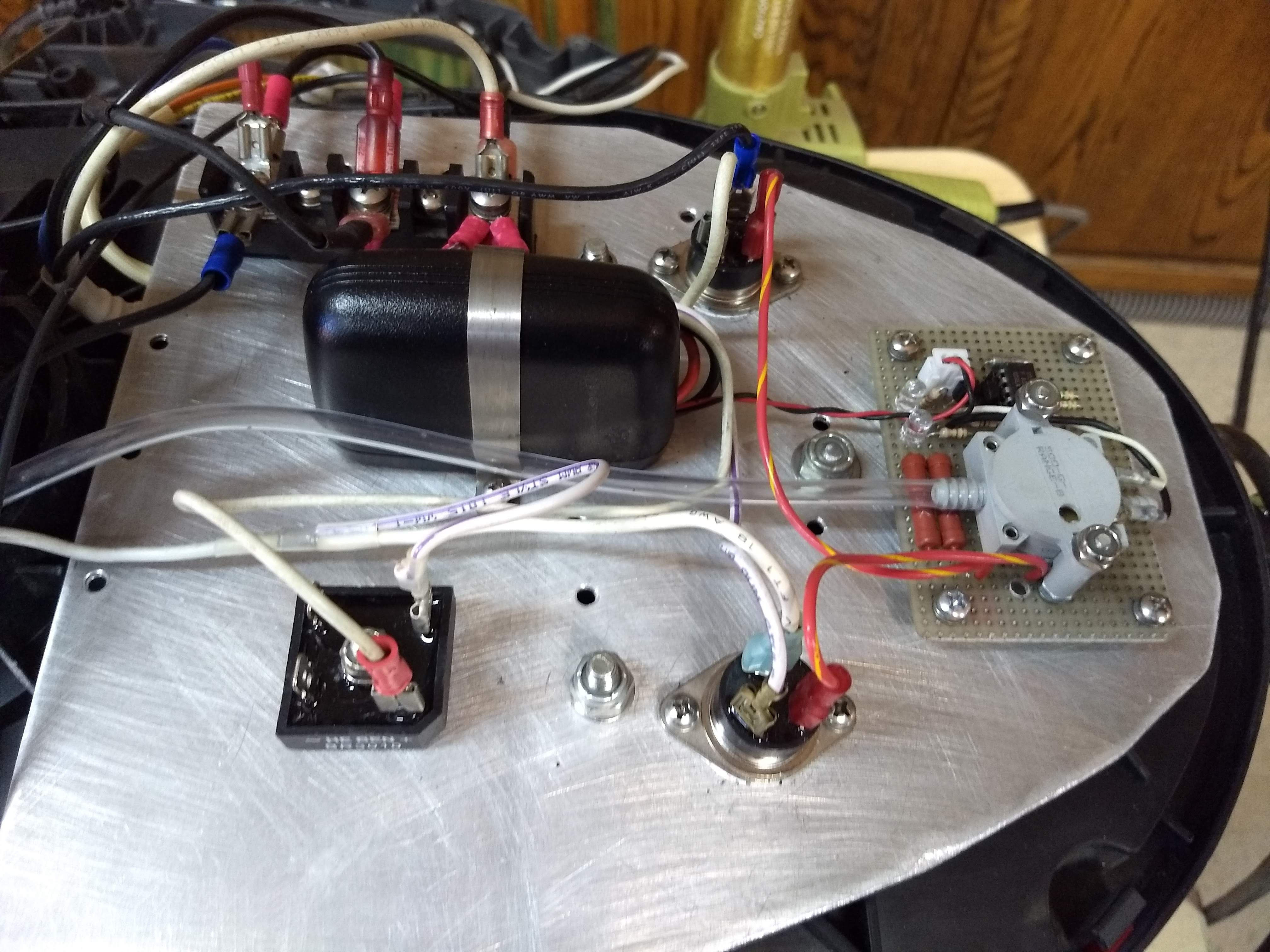
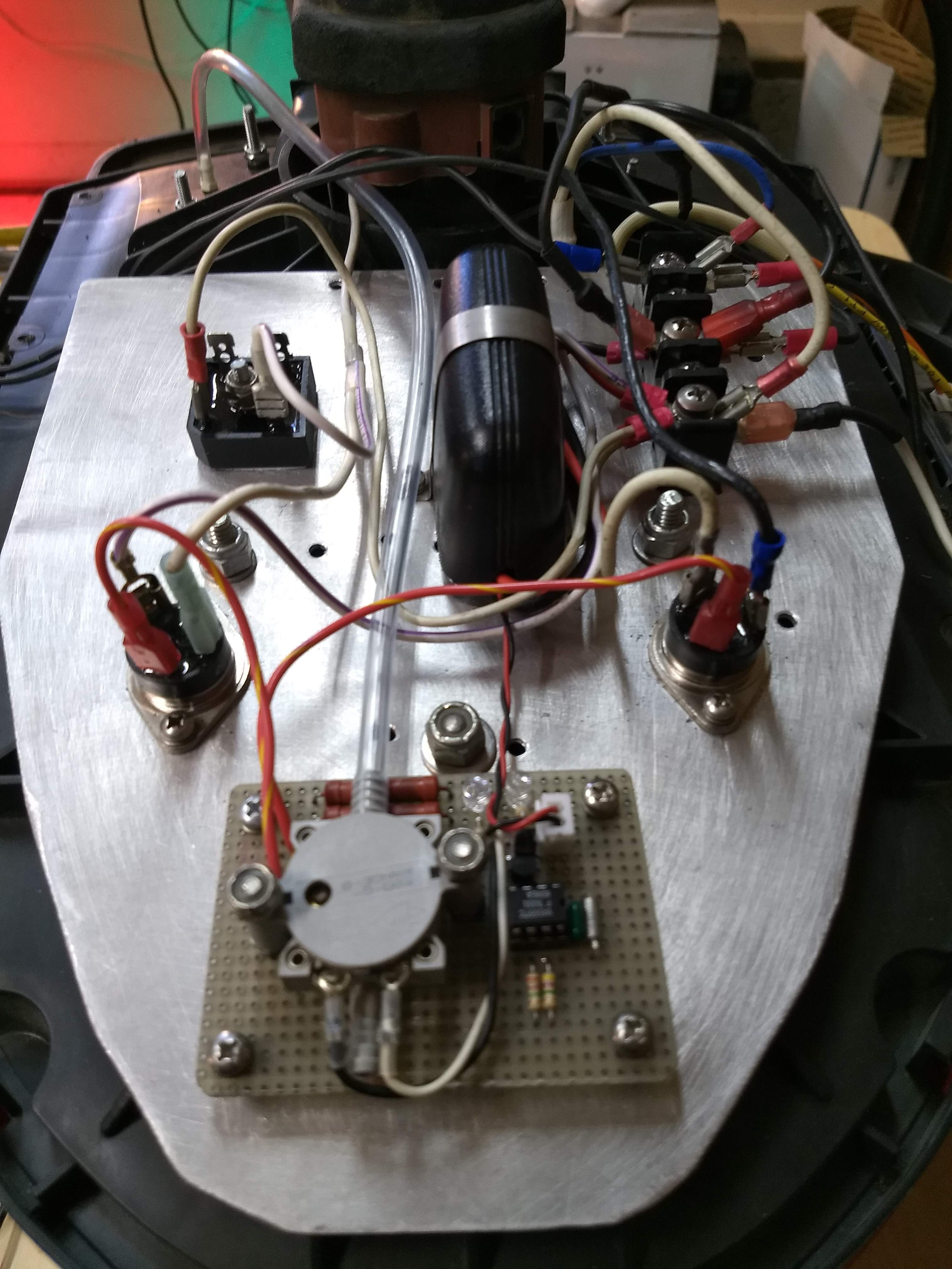
Mount components to the Driver Deck.
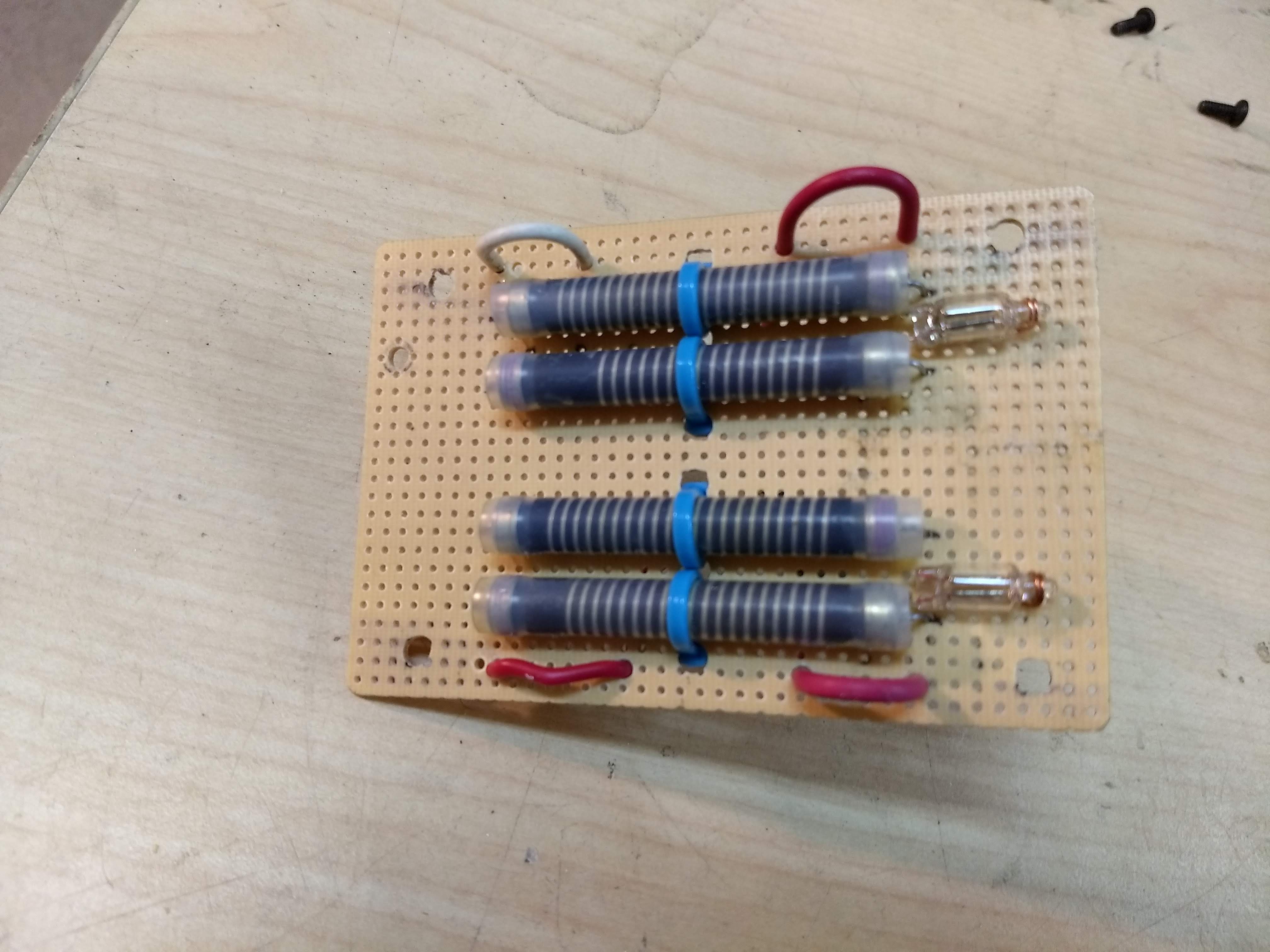
In this particular module, Teflon sleeving was slipped over the Gate Drive wires. And extra care was taken to center the gate drive leads in the toroid core windows. Voltage breakdown would be highly unlikely, even if the gate drive wires were bare.
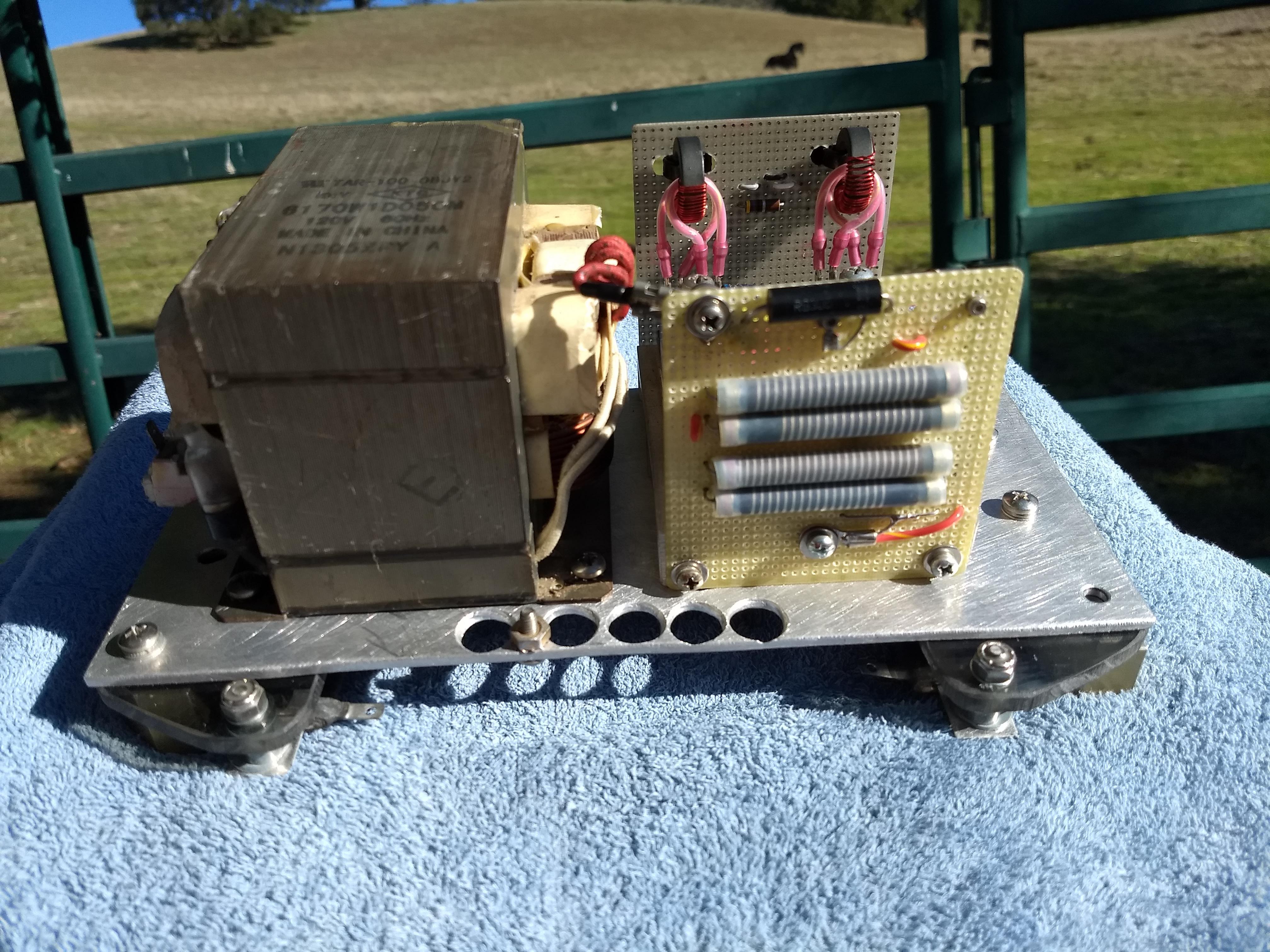
Notice how the 3-volt Magnetron filament-winding wires are threaded through a hole in the transformer core, then attached to a 6-volt incandescent lamp. This serves as a high voltage power indicator.
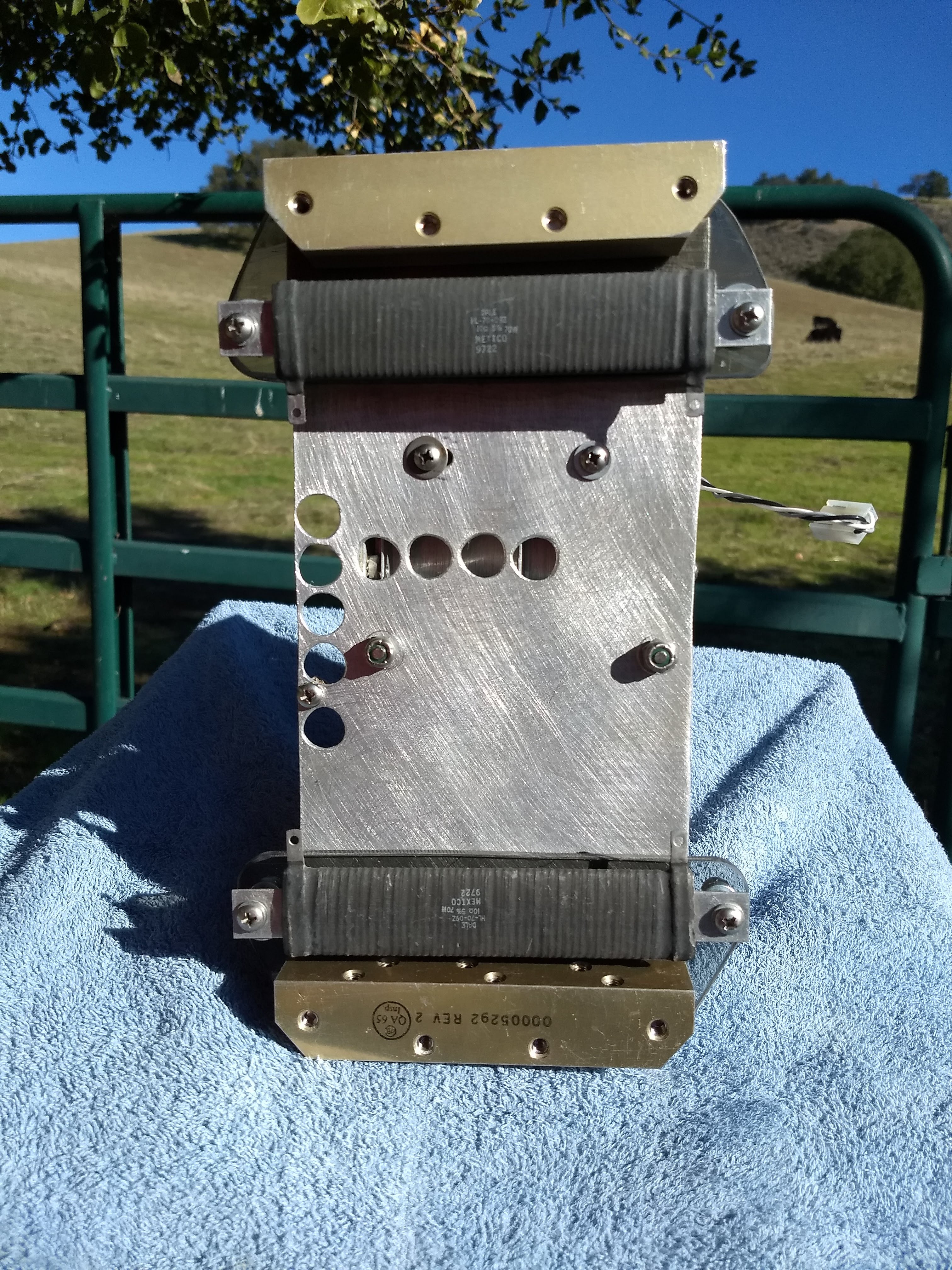
These resistors are inductive. That's fine here. They don't have adequate voltage rating, with respect to their mounting brackets. That's why they're mounted on insulating material (polycarbonate in this case). Large holes in the mounting plate direct airflow through the Switch deck heatsink, but that's really unnecessary. Those SCRs run cool.
6
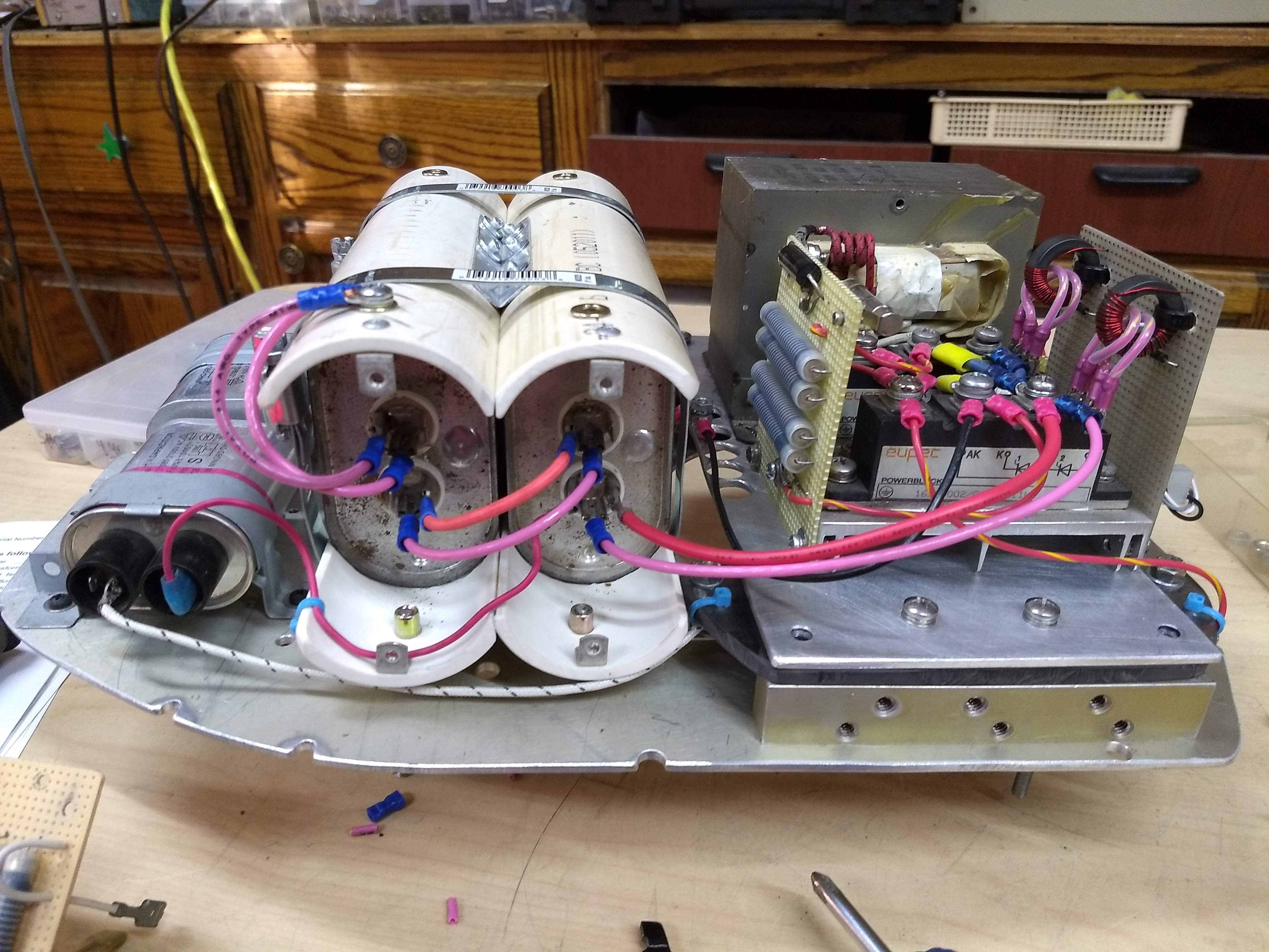
Construct Cap Bank
Connecting wires pass through holes in the board for strain relief. Bleeder wiring shall be fabricated with emphasis on reliability.
Mid-section rivet heads sit in counterbored holes. This spaces the rivet heads away from the capacitor bodies.
A trench is milled into the PVC, to accommodate the seams on the capacitor cases. This keeps them captive, so they can't slide around.


Discussions
Become a Hackaday.io Member
Create an account to leave a comment. Already have an account? Log In.