 kutluhan_aktar
-
1Step 1: Designing and soldering the Iron Giant-inspired PCB
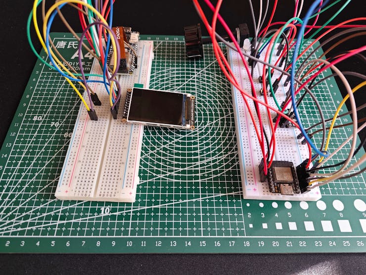
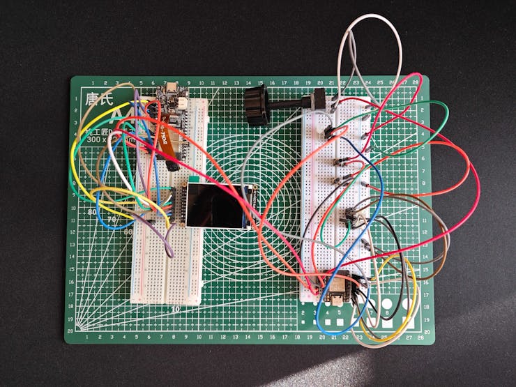
Before prototyping my Iron Giant-inspired PCB design, I tested all connections and wiring with FireBeetle 2 ESP32-S3 and Beetle ESP32-C3. Then, I checked the BLE connection quality between Beetle ESP32-C3 and the Android application for transferring data packets.
![]()
![]()
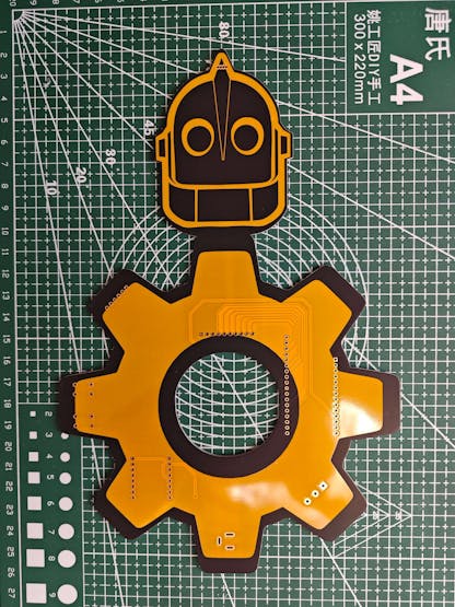
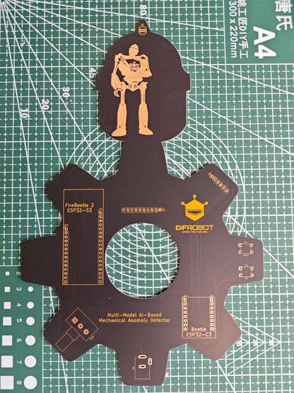
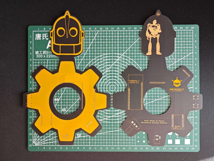
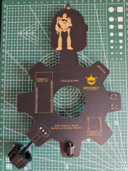
Then, I designed my Iron Giant-inspired PCB by utilizing Autodesk Fusion 360 and KiCad. Since I wanted to design a unique 3D-printed PCB holder to simplify cable management, I designed the PCB outline on Fusion 360 and then imported it to KiCad. As mentioned earlier, I drew my inspiration from Iron Giant's industrial-esque vibe and captivating demeanor to create a unique mechanical anomaly detector.
To replicate this anomaly detector, you can download the Gerber file below and order my PCB design from PCBWay directly.
![]()
![]()
![]()
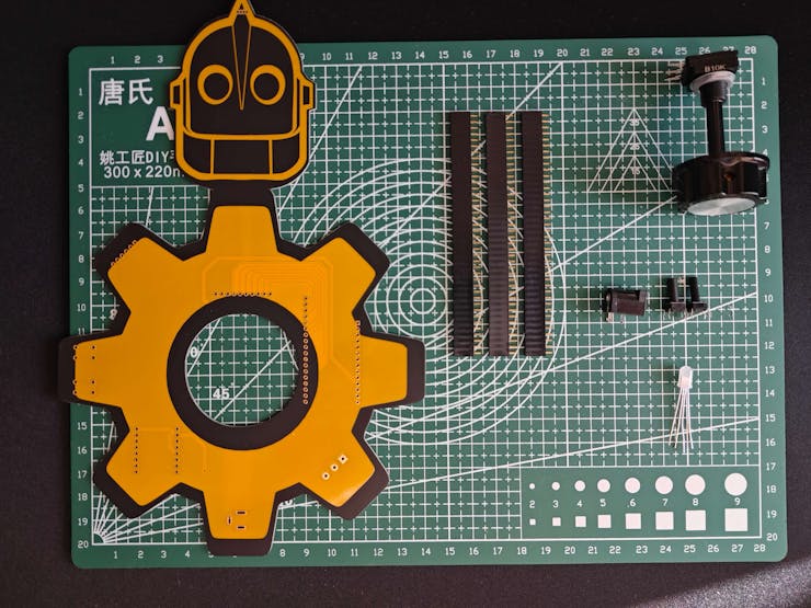
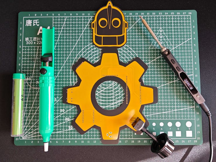
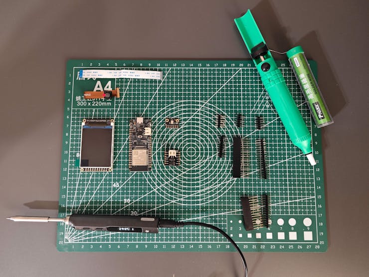
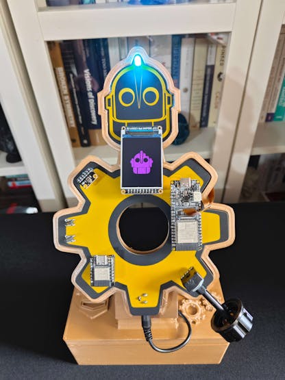
First of all, by utilizing a TS100 soldering iron, I attached headers (female), pushbuttons (6x6), a 5 mm common anode RGB LED, a long-shaft 10K potentiometer, and a power jack to the PCB.
📌 Component list on the PCB:
JF1, JF2 (Headers for FireBeetle 2 ESP32-S3)
JB1, JB2 (Headers for Beetle ESP32-C3)
S1 (Headers for Fermion IPS TFT LCD Display)
M1 (Headers for Fermion I2S MEMS Microphone)
RV1 (10K Long-shaft Potentiometer)
K1, K2 (6x6 Pushbutton)
D1 (5 mm Common Anode RGB LED)
P1 (Power Jack)
![]()
![]()
![]()
![]()
-
2Step 1.1: Making connections and adjustments
// Connections
// FireBeetle 2 ESP32-S3 :
//                                Fermion 2.0" IPS TFT LCD Display (320x240)
// 3.3V    ------------------------ V
// 17/SCK  ------------------------ CK
// 15/MOSI ------------------------ SI
// 16/MISO ------------------------ SO
// 18/D6   ------------------------ CS
// 38/D3   ------------------------ RT
// 3/D2    ------------------------ DC
// 21/D13  ------------------------ BL
// 9/D7    ------------------------ SC
//                                Beetle ESP32 - C3
// RX (44) ------------------------ TX (21)
// TX (43) ------------------------ RX (20)
&
&
&
// Connections
// Beetle ESP32 - C3 :
//                                Fermion: I2S MEMS Microphone
// 3.3V    ------------------------ 3v3
// 0       ------------------------ WS
// GND     ------------------------ SEL
// 1       ------------------------ SCK
// 4       ------------------------ DO
//                                Long-Shaft Linear Potentiometer
// 2       ------------------------ S
//                                Control Button (A)
// 8       ------------------------ +
//                                Control Button (B)
// 9       ------------------------ +
//                                5mm Common Anode RGB LED
// 5       ------------------------ R
// 6       ------------------------ G
// 7       ------------------------ B
//                                FireBeetle 2 ESP32-S3
// RX (20) ------------------------ TX (43)
// TX (21) ------------------------ RX (44)
#️⃣ Before testing connections and wiring on a breadboard, I needed to solder male headers to some components by utilizing the soldering iron.
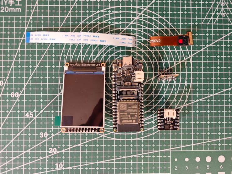
#️⃣ Since FireBeetle 2 ESP32-S3 provides a built-in camera interface with an independent camera power supply (AXP313A), I was able to attach the provided OV2640 camera effortlessly.
#️⃣ Since FireBeetle 2 ESP32-S3 and Beetle ESP32-C3 operate at 3.3V logic level voltage, I did not encounter any issues while connecting their hardware serial ports together.
#️⃣ Even though the Android application lets the user record audio samples via the phone microphone, since Beetle ESP32-C3 does not have an integrated microSD card module, I needed to connect a Fermion I2S MEMS microphone to Beetle ESP32-C3 in order to run the neural network model for audio classification in the field.
#️⃣ Then, I inserted a microSD card into the microSD card module on the Fermion TFT LCD display to save image samples easily. I also utilized the Fermion TFT LCD display to inform the user of the performed operations by showing the feature-associated icons.
#️⃣ Although the Android application allows the user to select a component (part) class to save image samples, I connected two control buttons and a long-shaft potentiometer to Beetle ESP32-C3 so as to provide the user with the option to save image samples and run the object detection model manually for debugging. Also, I added an RGB LED to inform the user of the device status while performing different operations.
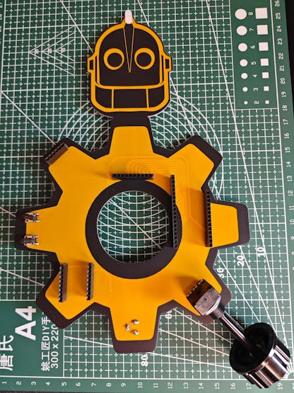
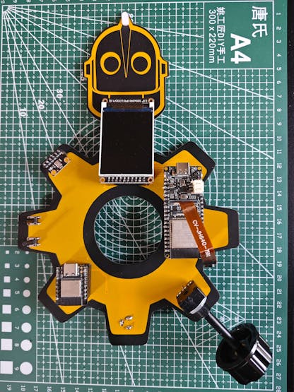
#️⃣ After completing soldering and adjustments, I attached all remaining components to the Iron Giant PCB via the female headers.
![]()
![]()
![]()
-
3Step 2: Designing and printing the Iron Giant-inspired case
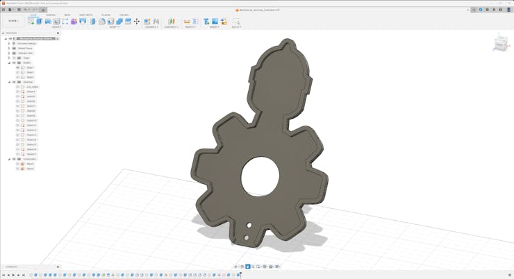
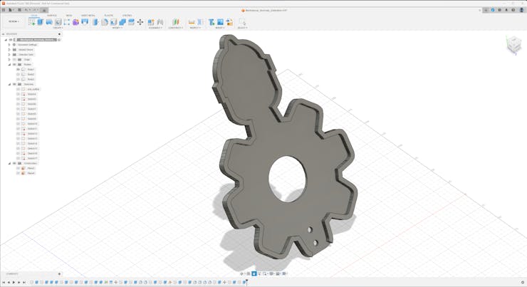
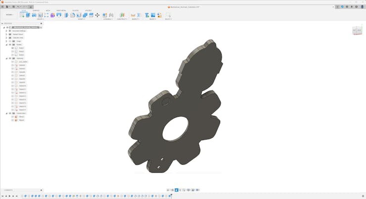
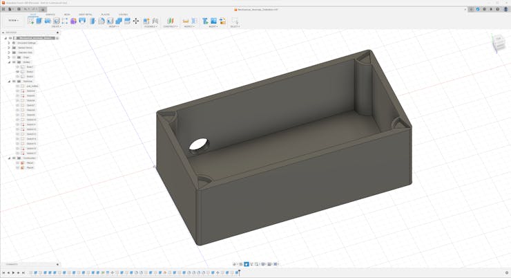
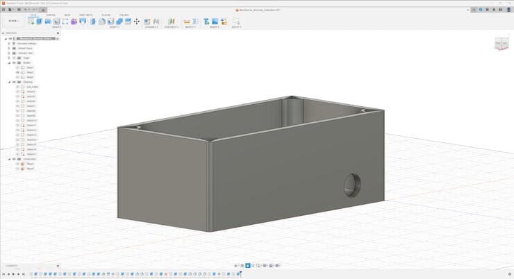
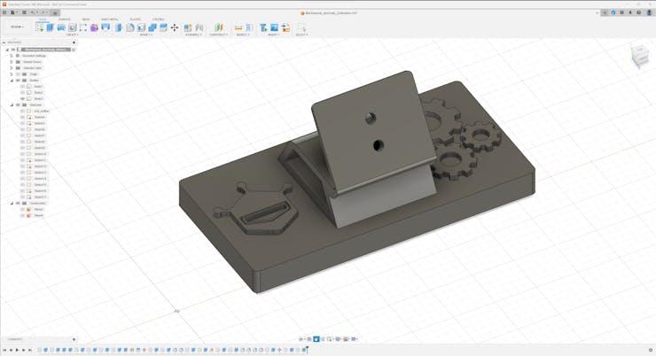
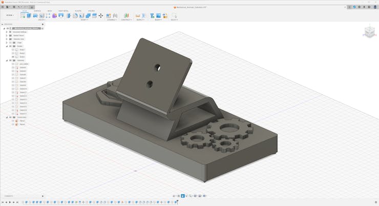
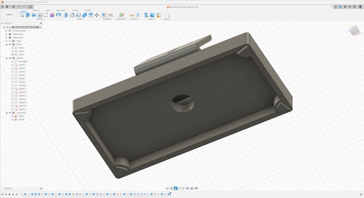
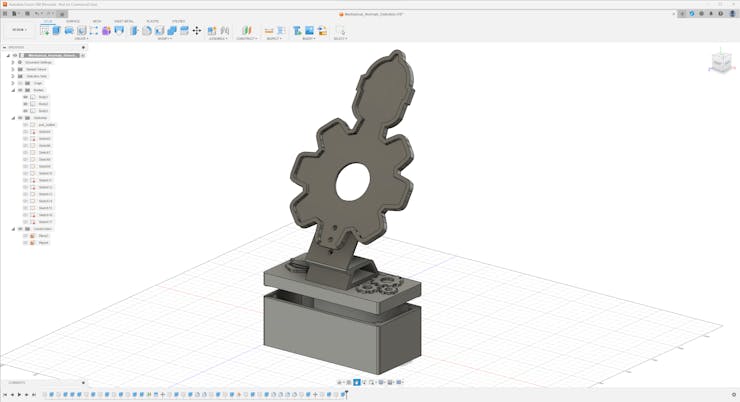
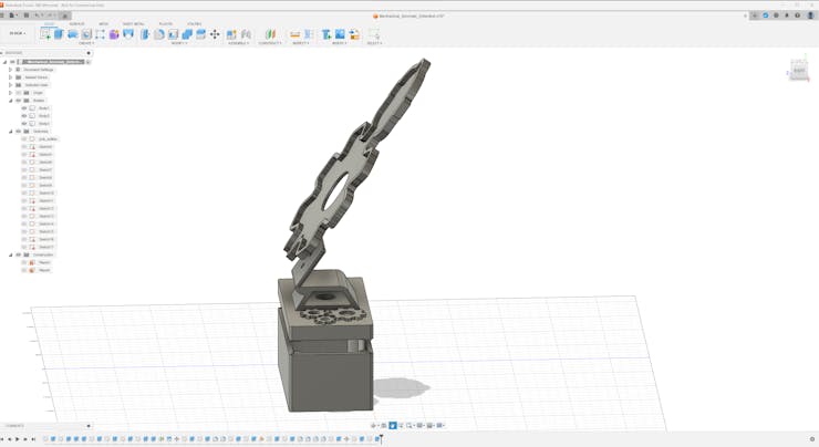
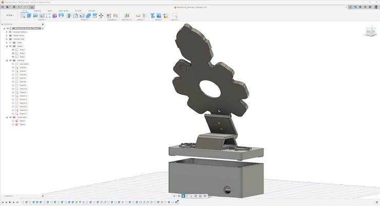
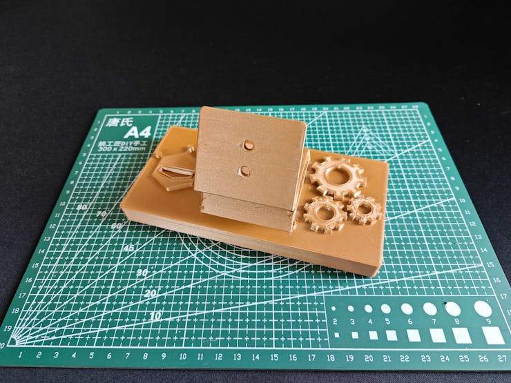
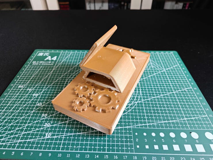
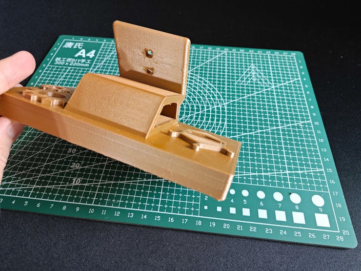
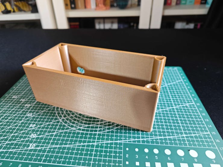
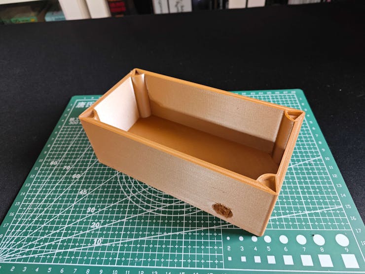
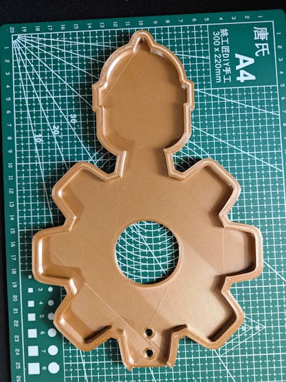
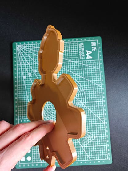
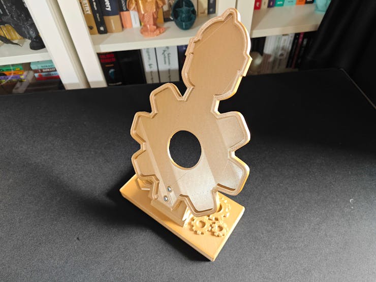
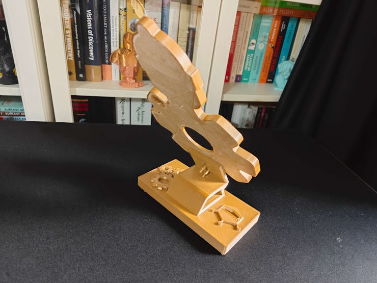
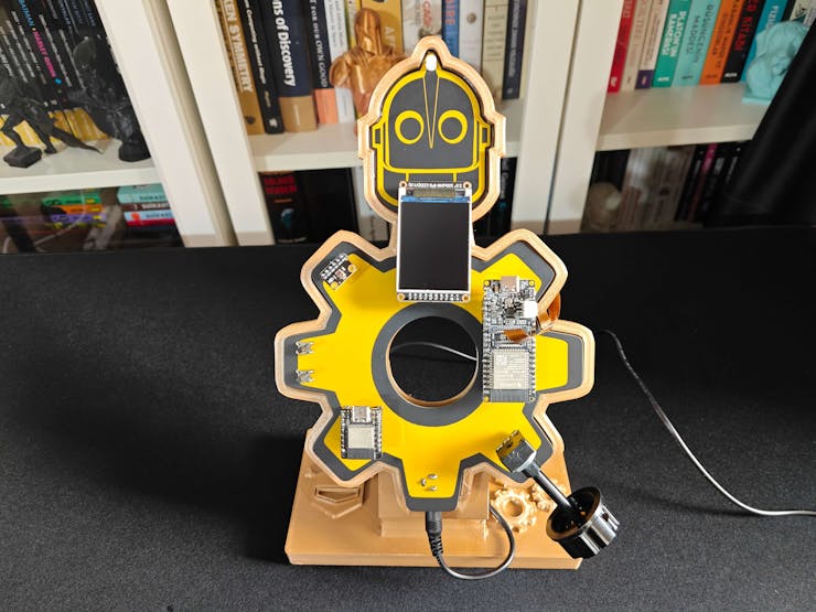
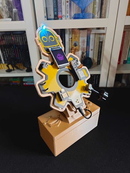
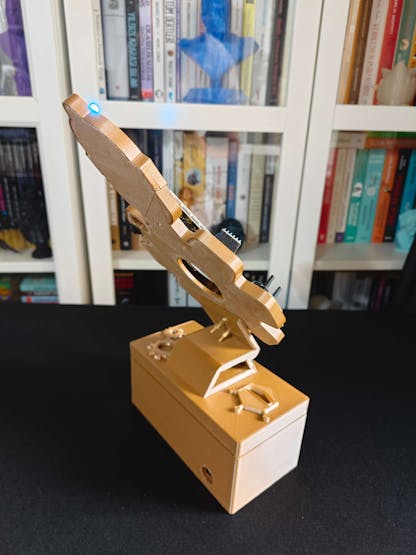
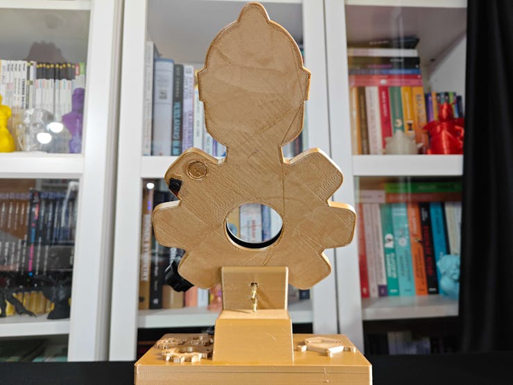
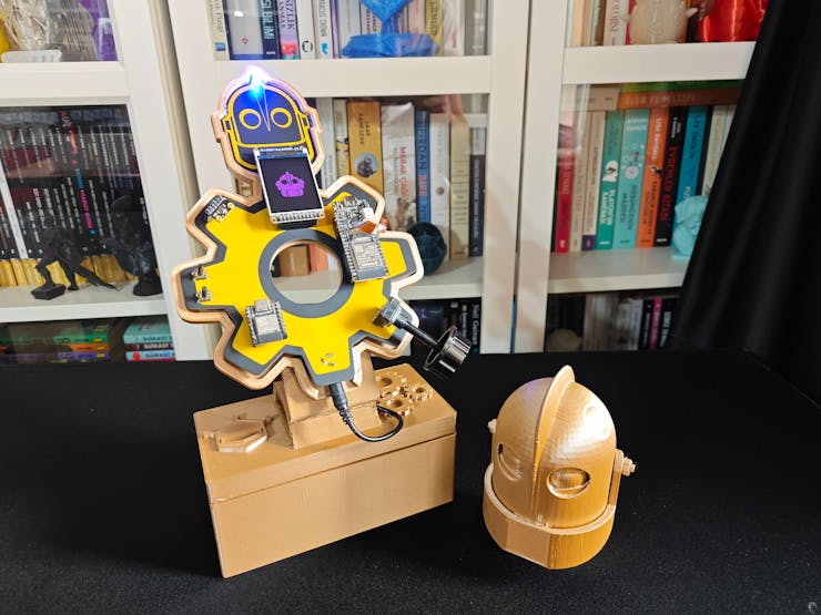
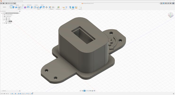
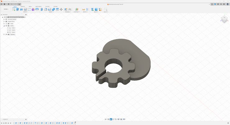
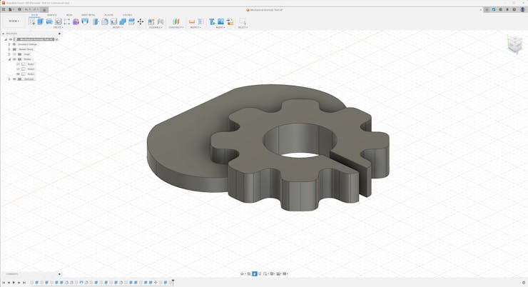
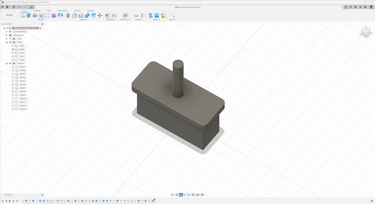
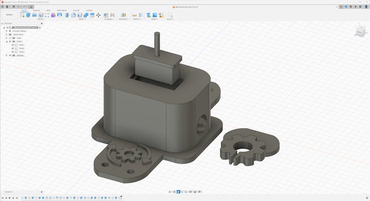
Since I focused on building a budget-friendly and accessible mechanical anomaly detector that detects sound-based mechanical anomalies and diagnoses the root cause of the detected deviations via object detection so as to notify the user via SMS, I decided to design a robust and compact case allowing the user to place the Iron Giant PCB and position the OV2640 camera on FireBeetle 2 ESP32-S3 effortlessly. To avoid overexposure to dust and prevent loose wire connections, I added a removable top cover mountable to the main case via triangular snap-fit joints. Then, I designed a unique PCB holder by utilizing the PCB outline, mountable to the top cover diagonally via M3 screws and nuts. Also, I decided to emboss gear icons and the DFRobot symbol on the top cover to emphasize the capabilities of this AI-based mechanical anomaly detector.
Since I drew my inspiration from Iron Giant's industrial-esque vibe while designing this mechanical anomaly detector, I decided to print an Iron Giant bust to highlight the design similarities.
I designed the main case, the removable top cover, and the PCB holder in Autodesk Fusion 360. You can download their STL files below.
![]()
![]()
![]()
![]()
![]()
![]()
![]()
![]()
![]()
![]()
![]()
For the Iron Giant bust accentuating the device design, I utilized this model from Thingiverse:
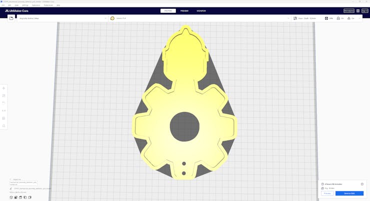
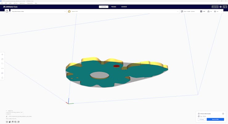
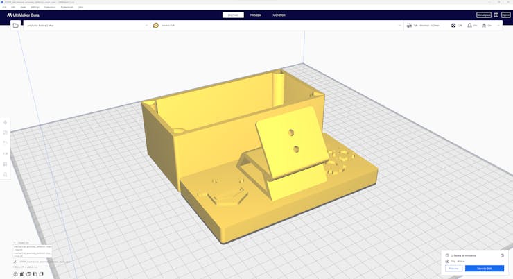
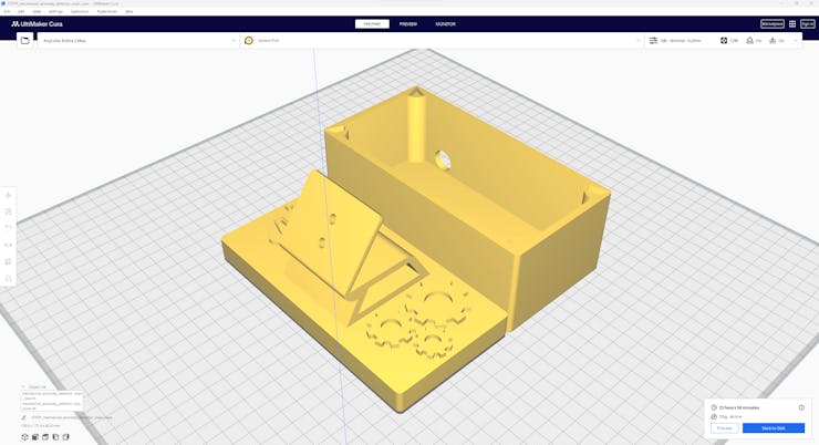
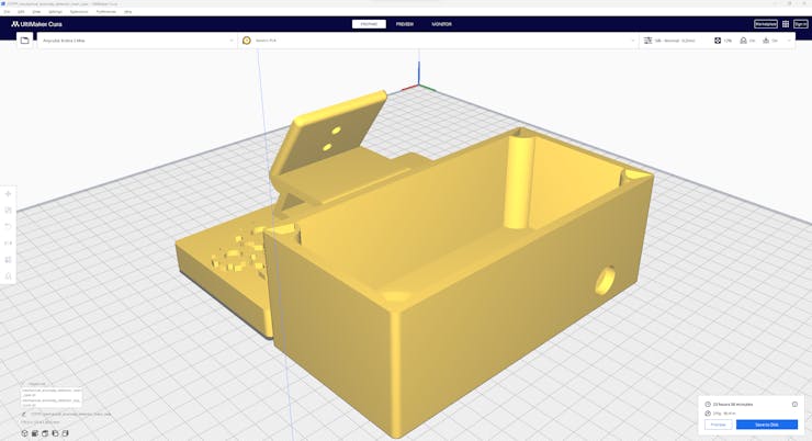
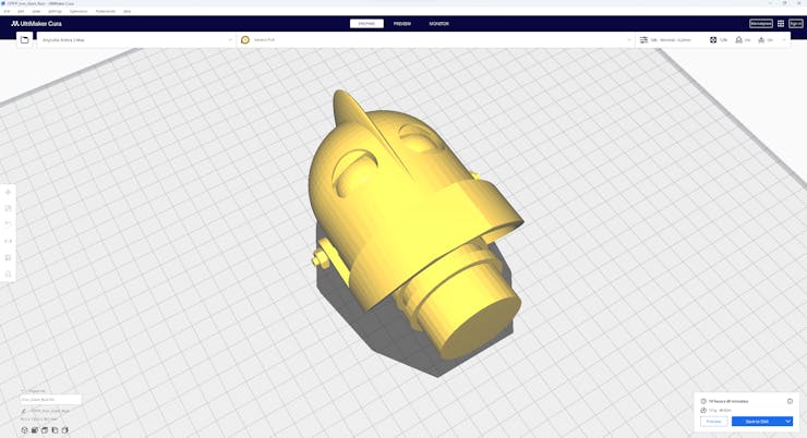
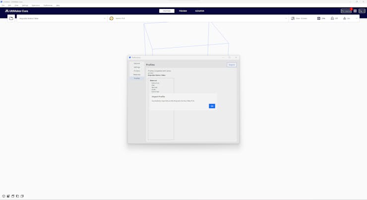
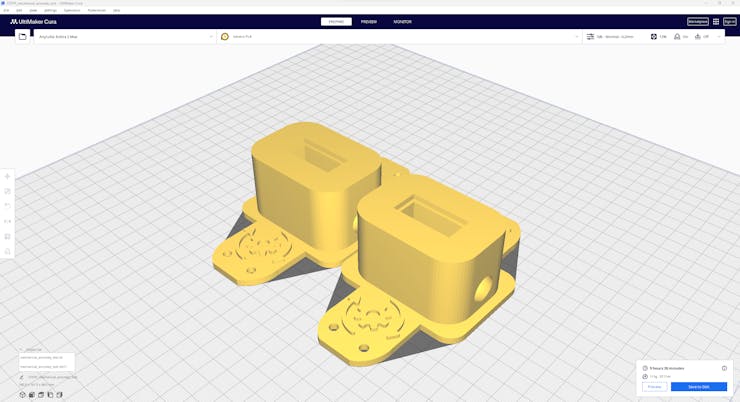
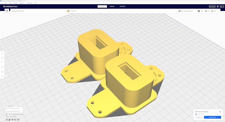
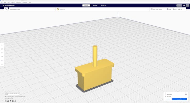
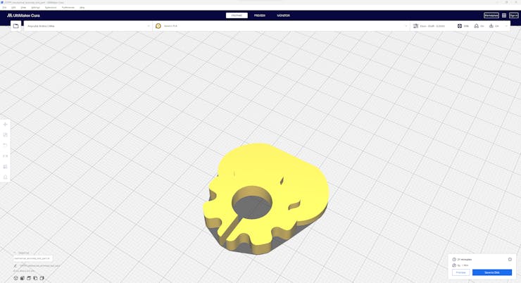
Then, I sliced all 3D models (STL files) in Ultimaker Cura.
![]()
![]()
![]()
![]()
![]()
![]()
Since I wanted to create a metallic structure for the device case and apply a unique industrial-esque theme manifesting mechanical plants, I utilized this PLA filament:
- ePLA-Metal Antique Brass
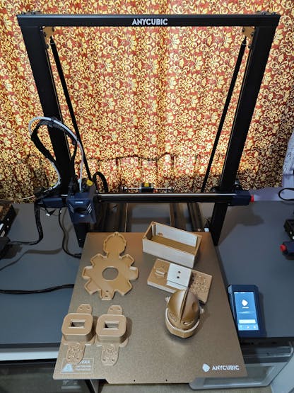
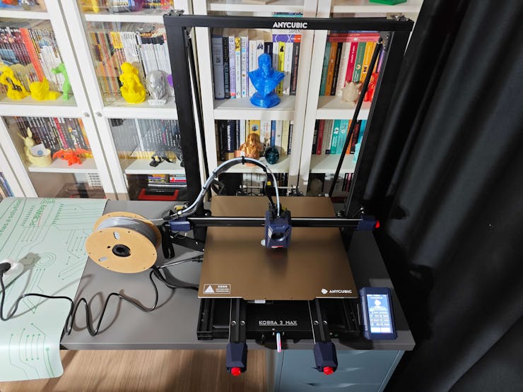
Finally, I printed all parts (models) with my brand-new Anycubic Kobra 2 Max 3D Printer.
![]()
Since Anycubic Kobra 2 Max is budget-friendly and specifically designed for high-speed printing with a gigantic build volume, I highly recommend Anycubic Kobra 2 Max if you are a maker or hobbyist needing to print large prints without compartmentalizing your design and losing structural integrity while working on multiple prototypes before finalizing a complex project.
Thanks to its upgraded direct extruder and vibration compensation features, Anycubic Kobra 2 Max provides 300 mm/s recommended print speed (up to 500 mm/s) and enhanced layer quality. Also, it provides a high-speed optimized cooling system, reducing visible layer lines and complementing the fast printing experience. Since the Z-axis has dual-motors and dual-support rods, it prevents vibration from affecting layer smoothness and integrity, even at higher print speeds.
Furthermore, Anycubic Kobra 2 Max provides a magnetic suction platform on the heated bed for the scratch-resistant PEI spring steel build plate, allowing the user to remove prints without any struggle, even for larger prints up to 420x420x500 mm. Most importantly, you can level the bed automatically via its user-friendly LeviQ 2.0 automatic leveling system and custom Z-axis compensation. Also, it has a smart filament runout sensor and supports Anycubic APP for remote control and management.
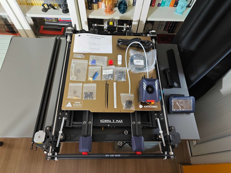
#️⃣ First of all, remove all fixing plates. Then, install the gantry frame and support rods.
![]()
![]()
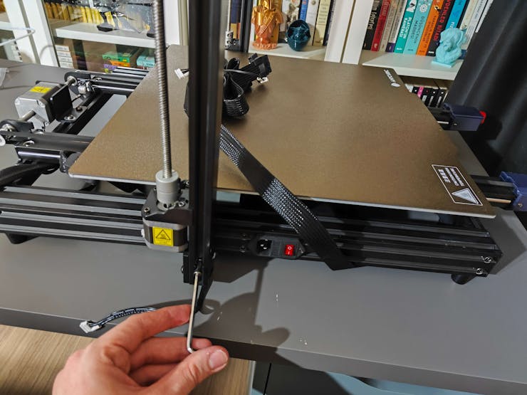
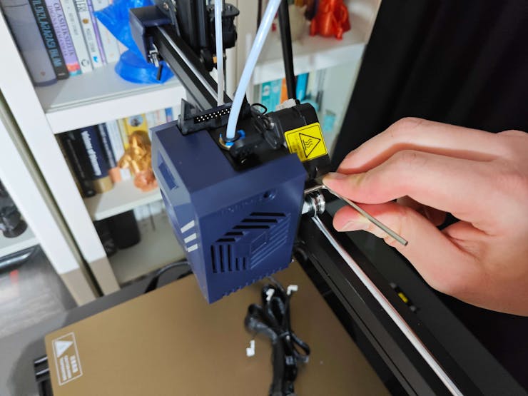
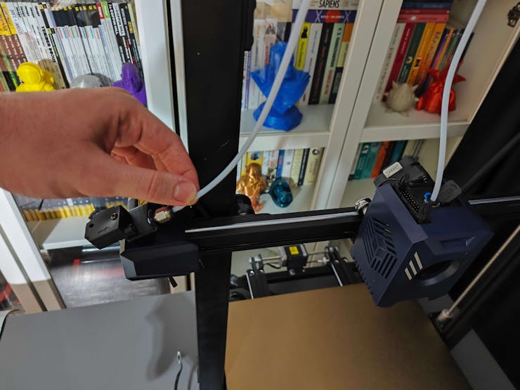
#️⃣ Install the print head and adjust the X-axis belt tensioner. Then, install the touchscreen and the filament runout sensor.
![]()
![]()
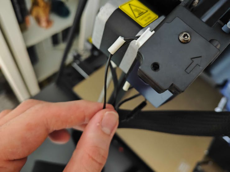
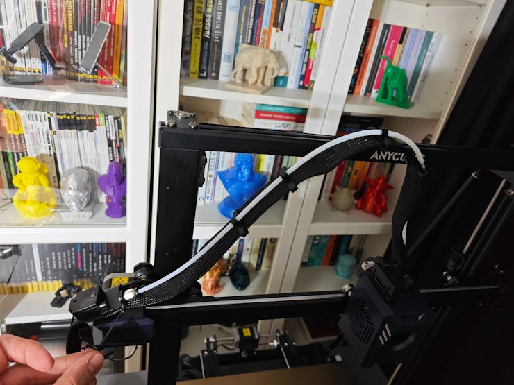
#️⃣ Connect the stepper, switch, screen, and print head cables. Then, attach the filament tube and use cable ties to secure the cables properly.
![]()
![]()
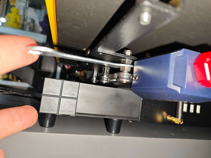
#️⃣ If the print head or bed is shaking, adjust the hexagonal isolation columns underneath them.
![]()
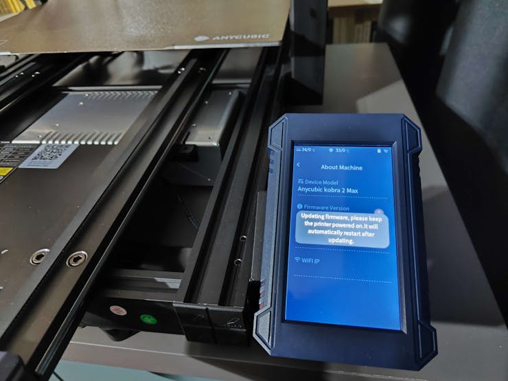
#️⃣ To avoid software-related print failures, update the device firmware manually via USB or directly over Wi-Fi.
I encountered some errors due to Cura configurations before the official 2.3.6 firmware.
![]()
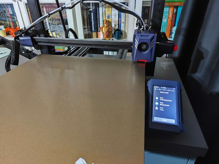
#️⃣ After the firmware upgrade, go to Settings ➡ More Settings ➡ Guide so as to initiate the LeviQ 2.0 automatic bed leveling system and configure vibration calibration.
![]()
#️⃣ Finally, fix the filament tube with the cable clips, install the filament holder, and insert the filament into the extruder.
![]()
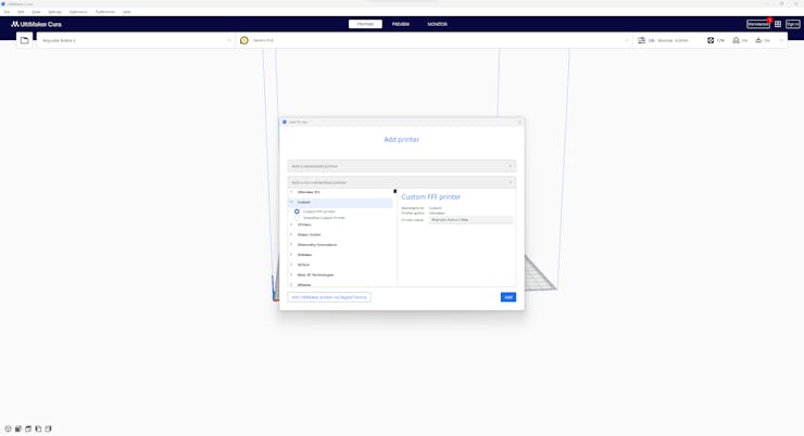
#️⃣ Since Anycubic Kobra 2 Max is not officially supported by Cura yet, we need to set it manually. Fortunately, Anycubic provides detailed configuration steps for Anycubic Kobra 2 Max on Cura.
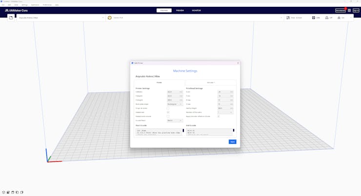
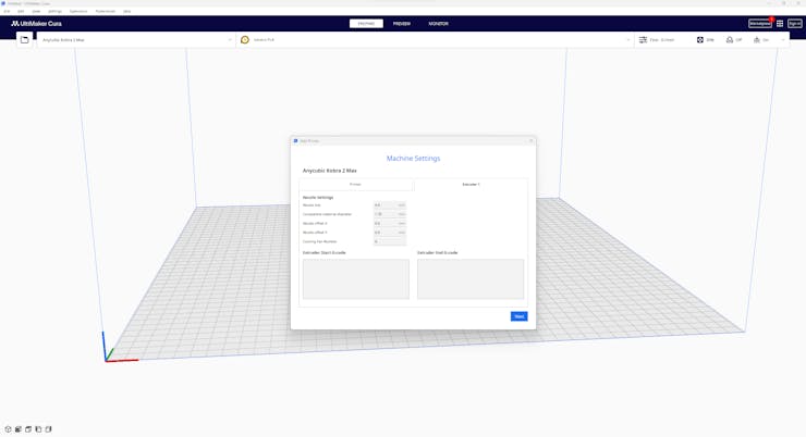
#️⃣ First of all, create a custom printer profile on Cura for Anycubic Kobra 2 Max with given printer settings.
![]()
![]()
![]()
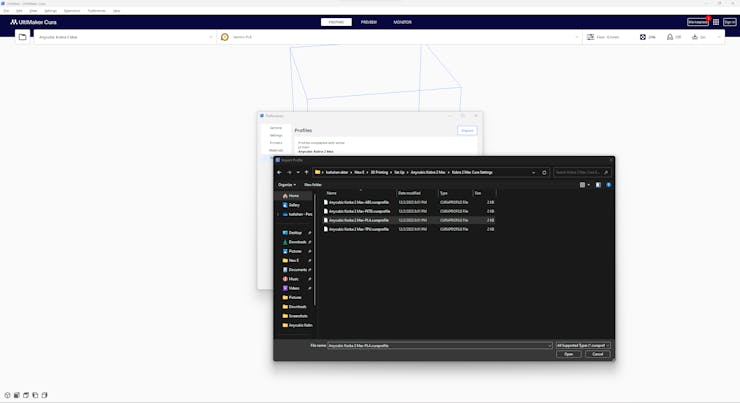
#️⃣ Then, import the printer profile (configuration) file provided by Anycubic, depending on the filament type.
![]()
![]()
-
4Step 2.1: Assembling the 3D-printed case
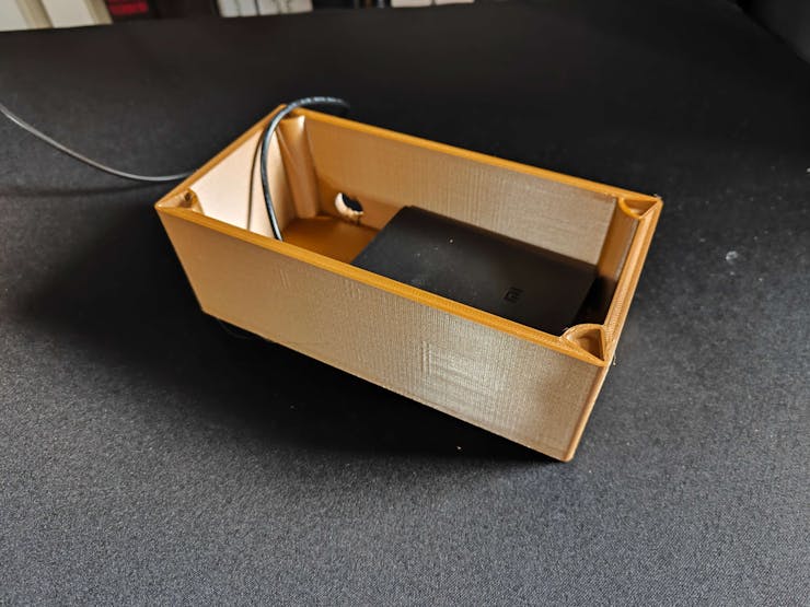
After printing all parts (models), I fastened the external battery (Xiaomi 10000 mAh power bank) into the main case via a hot glue gun.
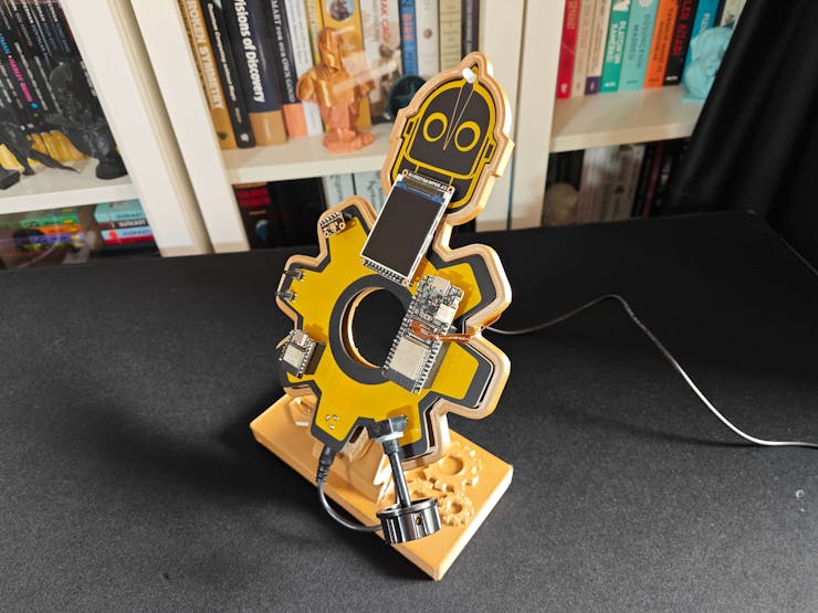
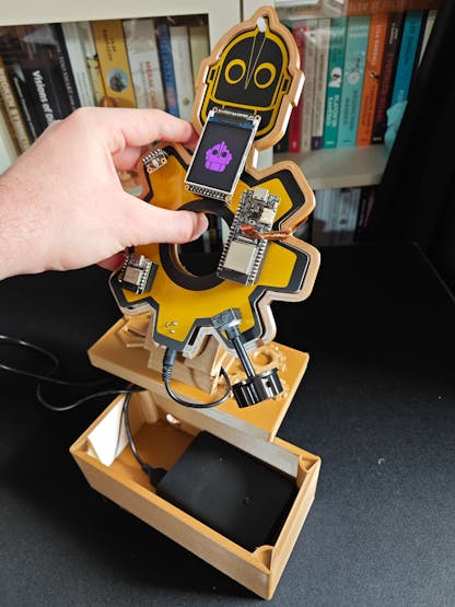
Then, I attached the PCB holder to the removable top cover via M3 screws and nuts. After mounting the PCB holder, I fastened the Iron Giant PCB to the PCB holder via the hot glue gun. I also attached the built-in OV2640 camera to the back of the PCB holder via the hot glue gun.
Since the top cover has a slot for the USB power cable, the PCB power jack can be directly connected to the external battery contained in the main case.
Finally, I affixed the top cover to the main case via its triangular snap-fit joints.
![]()
![]()
![]()
![]()
![]()
![]()
![]()
![]()
![]()
![]()
![]()
![]()
![]()
![]()
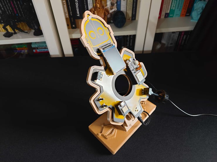
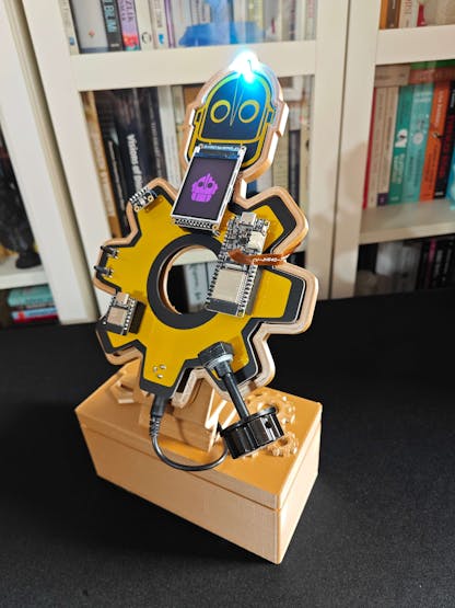
Since the main case supports the cable-free PCB assembly, the anomaly detector can be placed in any machinery effortlessly.
![]()
![]()
![]()
![]()
![]()
After completing the case assembly, I showcased my mechanical anomaly detector with the Iron Giant bust to emphasize the design resemblances.
![]()
-
5Step 3: Designing a frequency-controlled apparatus to demonstrate mechanical anomalies w/ Arduino Mega
As explained earlier, each manufacturing system requires a unique approach to mechanical anomaly detection due to conflicting mechanical deviations, especially for interconnected processes. Therefore, engineers must deliberately specialize the optimal anomaly detection method to minimize false negatives (or positives), yield exceptional accuracy, and maintain stable equipment performance.
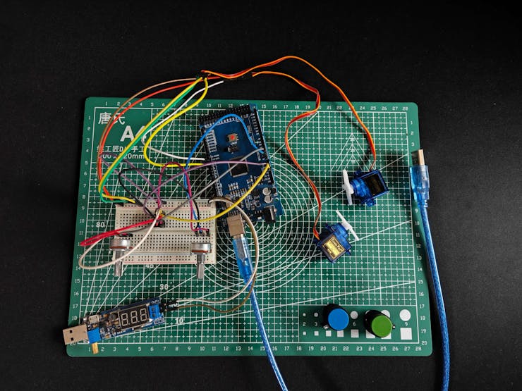
Since I did not have the resources to examine an industrial plant or production line while working on this project, I decided to build a basic frequency-controlled apparatus based on Arduino Mega to manifest mechanical anomalous behavior. Thanks to this apparatus, I was able to adjust each operational parameter while constructing my audio-based data set. Therefore, I managed to apply proper tuning to my anomaly detection method.
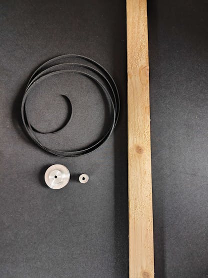
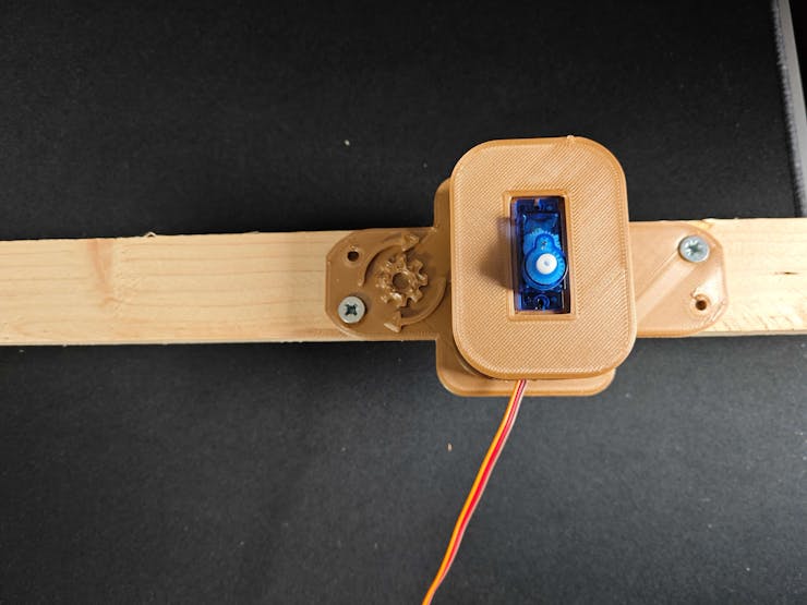
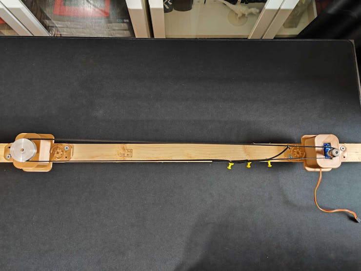
I decided to replicate the X-axis timing belt system of a 3D printer to build my testing apparatus since it is easier to demonstrate mechanical anomalies with single-purposed mechanisms. In that regard, I utilized a GT2 60T pulley, a GT2 20T pulley, and a 6 mm belt as the timing belt system. Since I decided to move the timing belt manually via potentiometers, I decided to utilize SG90 servo motors instead of stepper motors.
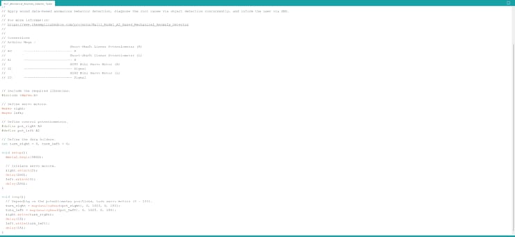
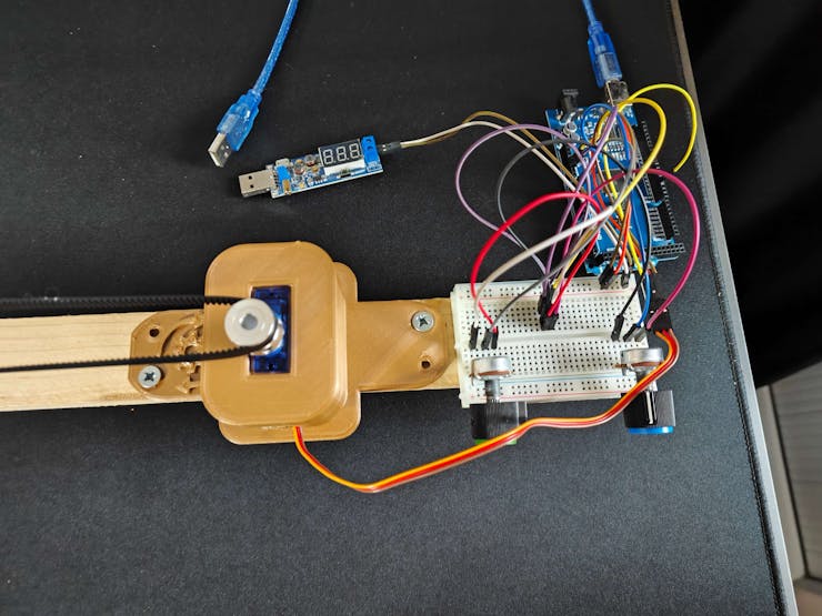
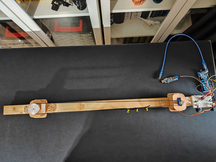
Since I had a spare Arduino Mega, I employed it to control servo motors with potentiometers. You can inspect the code for moving the timing belt below — AIoT_Mechanical_Anomaly_Detector_Tester.ino.
// Depending on the potentiometer positions, turn servo motors (0 - 180). turn_right = map(analogRead(pot_right), 0, 1023, 0, 180); turn_left = map(analogRead(pot_left), 0, 1023, 0, 180); right.write(turn_right); delay(15); left.write(turn_left); delay(15);
![]()
![]()
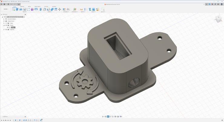
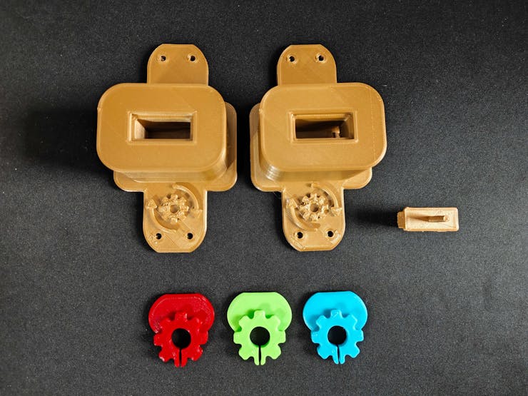
After testing wiring and connections, I designed a motor mount compatible with the SG90 servo motor. I also designed a simple GT2 60T pulley holder to utilize the timing belt system with one servo motor and potentiometer pair.
Although I was able to generate anomalies by shifting the belt manually, I decided to design three diverse (color-coded) 3D components (parts) restricting the belt movement in order to exemplify the root cause of the induced mechanical anomaly for the object detection model.
I designed the servo motor mount, the pulley holder, and the restricting components in Autodesk Fusion 360. You can download their STL files below.
![]()
![]()
![]()
![]()
![]()
![]()
Then, I sliced all 3D models (STL files) in Ultimaker Cura.
![]()
![]()
![]()
![]()
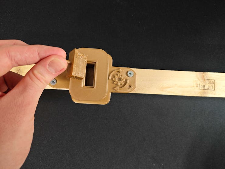
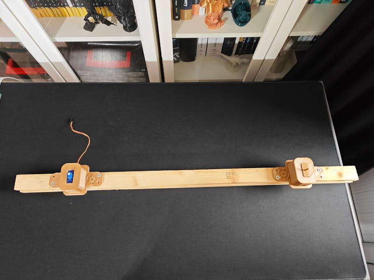
#️⃣ First of all, screw the servo motor mounts into the double-layer plywood.
![]()
![]()
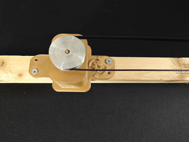
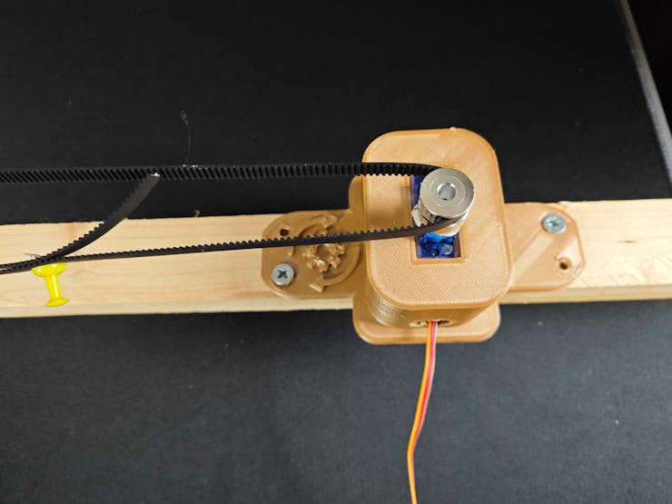
#️⃣ Attach the SG90 servo motor and the GT2 60T pulley holder to the servo motor mounts via their slots.
![]()
![]()
![]()
#️⃣ Position the GT2 60T pulley and the GT2 20T pulley. Then, tension the 6 mm timing belt between them with clamps (or pins).
![]()
![]()
![]()
#️⃣ Finally, fasten the half-sized breadboard to the plywood, including the adjustment potentiometers.
![]()
![]()
-
6Step 4: Developing a Wi-Fi and BLE-enabled Android application w/ the MIT APP Inventor
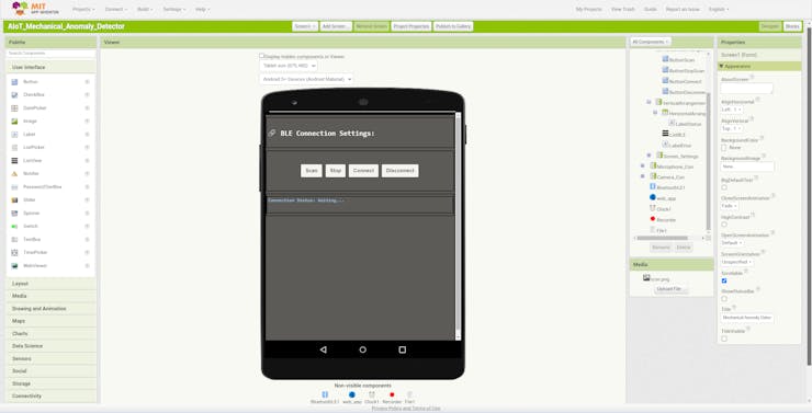
Although this mechanical anomaly detector utilizes two separate development boards to operate, I wanted to enable the user to access all interconnected device features within a single interface, especially for data collection. Since I wanted to capitalize on smartphone features to build a feature-rich mechanical anomaly detector, I decided to develop an Android application from scratch with the MIT APP Inventor. As the user interface of the anomaly detector, the Android application can:
- utilize the Wi-Fi network connection to retrieve model detection results with resulting images from the web application by making HTTP GET requests,
- save audio samples (3GP files) to the internal storage (application root folder) through the built-in phone microphone,
- communicate with Beetle ESP32-C3 via BLE so as to obtain audio-based anomaly detection results (neural network model) and transmit selected classes for image sample collection with FireBeetle 2 ESP32-S3.
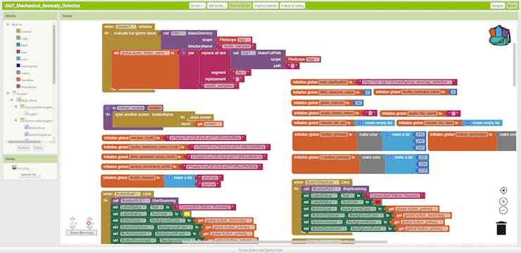
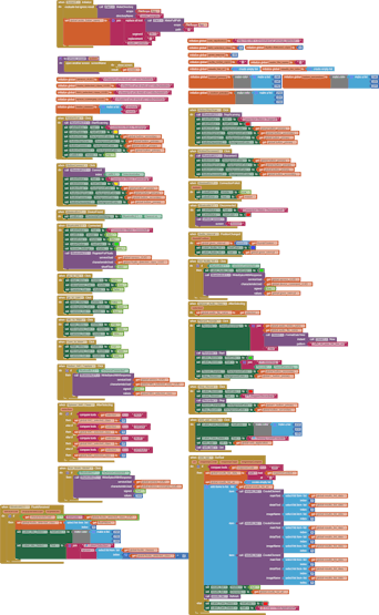
MIT App Inventor is an intuitive visual programming environment that allows developers to build fully functional Android applications. Its blocks-based tool (drag-and-drop) facilitates the creation of complex high-impact apps in significantly less time than the traditional programming environments.
After developing my application, named Mechanical Anomaly Detector, I published it on Google Play. So, you can install this application on any compatible Android device via Google Play.
📲 Install Mechanical Anomaly Detector on Google Play
Also, you can download the application's APK file directly below.
Nevertheless, if you want to replicate or modify this Android application on the MIT App Inventor, follow the steps below.
#️⃣ First of all, create an account on the MIT App Inventor.
#️⃣ Download the Mechanical Anomaly Detector app's project file in the AIA format (Mechanical_Anomaly_Detector.aia) and import the AIA file into the MIT App Inventor.
#️⃣ Since the MIT App Inventor does not support BLE connectivity by default, download the latest version of the BluetoothLE extension and import the BluetoothLE extension into the Mechanical Anomaly Detector project.
#️⃣ In this tutorial, you can get more information regarding enabling BLE connectivity on the MIT App Inventor.
![]()
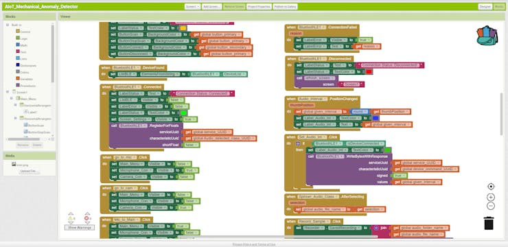
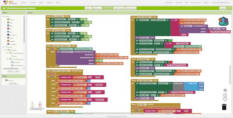
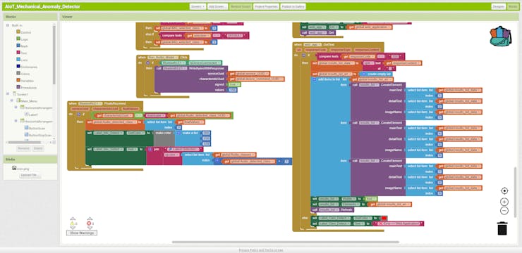
#️⃣ In the Blocks editor, you can inspect the functions I programmed with the drag-and-drop menu components.
#️⃣ In the following steps, you can get more information regarding all features of this Android application working in conjunction with Beetle ESP32-C3 and the web application.
Since the built-in sound recorder object can only access the ASD (app-specific dir), I saved the audio samples (3GP) to the audio_samples folder in the root directory of the application.
![]()
![]()
![]()
![]()
![]()
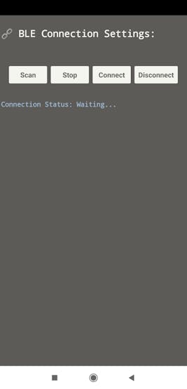
After installing this Android application on a compatible mobile phone, you can start communicating with Beetle ESP32-C3 over BLE to access all interconnected features of this mechanical anomaly detector.
![]()
-
7Step 5: Creating an account to utilize Twilio's SMS API
Since I decided to notify the user of the latest detected audio-based anomaly and the diagnosed root cause (faulty component) via SMS, I needed to utilize Twilio's SMS API. In this regard, I was also able to transfer the prediction date and the resulting image link through the web application.
Twilio provides a trial text messaging service to transfer an SMS from a virtual phone number to a verified phone number internationally. Also, Twilio supports official helper libraries for different programming languages, including PHP, enforcing its suite of APIs.
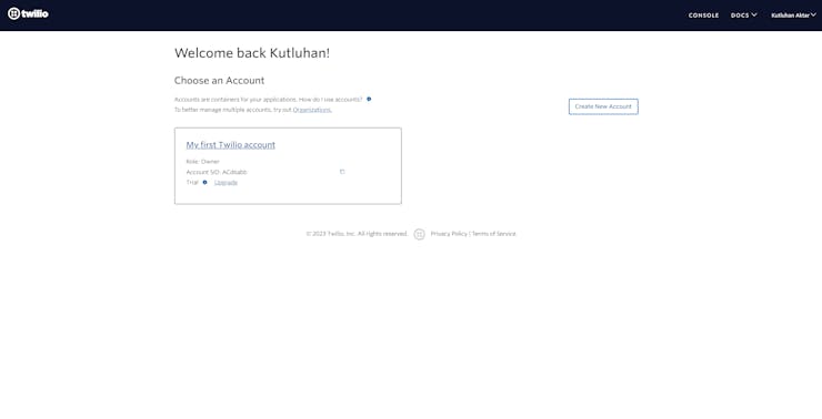
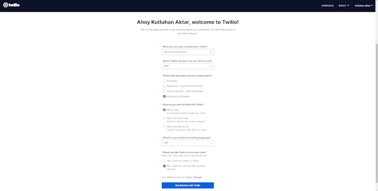
#️⃣ First of all, sign up for Twilio and navigate to the default (provided) trial account (project).
I noticed that creating free subsidiary accounts (projects) more than once may lead to the permanent suspension of a Twilio user account. So, I recommend using the default trial account (project) for each new iteration if not subscribed to a paid plan.
![]()
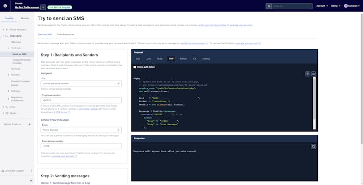
#️⃣ After verifying a phone number for the selected account (project), set the initial account settings for SMS in PHP.
![]()
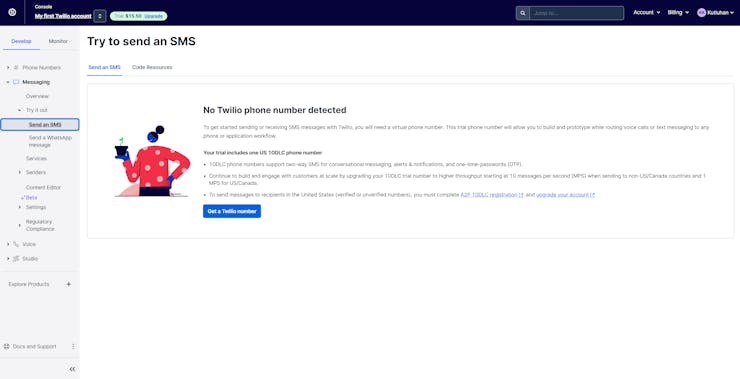
#️⃣ To configure the SMS settings, go to Messaging ➡ Send an SMS.
#️⃣ Since a virtual phone number is required to transfer an SMS via Twilio, click Get a Twilio number.
![]()
#️⃣ Since Twilio provides a trial (free) 10DLC phone number for each trial account, it lets the user utilize the text messaging service immediately after assigning a virtual phone number to the given account.
#️⃣ After activating the virtual number, download the Twilio PHP Helper Library to send an SMS via the web application.
![]()
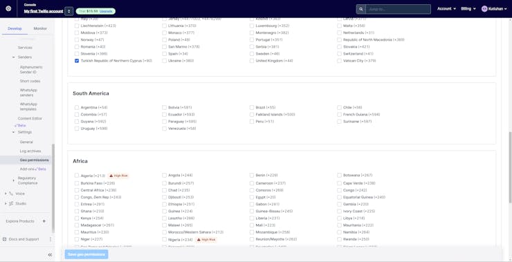
#️⃣ Finally, go to Geo permissions to adjust the allowed recipients depending on your region.
![]()
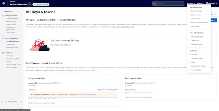
#️⃣ After configuring SMS settings, go to Account ➡ API keys & tokens to get the account SID and the auth token under Live credentials so as to employ Twilio's SMS API to send SMS.
![]()
-
8Step 6: Developing a web application to communicate w/ the Android app and process requests from FireBeetle 2 ESP32-S3
Since I needed to obtain the model detection results and the resulting image from FireBeetle 2 ESP32-S3 after running the object detection model so as to notify the user, I decided to develop a basic web application to utilize Twilio's SMS API.
Also, the web application converts the received raw image buffer (RGB565) to a JPG file and draws the bounding box generated by the model on the converted image by executing a Python script.
In addition to creating the modified resulting images, the web application transfers the latest object detection results, the prediction dates, and the modified resulting images (URLs) to the Android application in an indexed list as the response to an HTTP GET request.
As shown below, the web application consists of four folders and four code files:
- /assets
- -- /twilio-php-main
- -- class.php
- /detections
- -- /images
- -- rgb565_converter.py
- results.php
- update.php
![]()
![]()
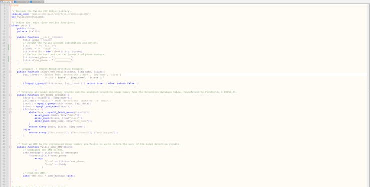
📁 class.php
In the class.php file, I created a class named _main to bundle the following functions under a specific structure.
⭐ Include the Twilio PHP Helper Library.
require_once 'twilio-php-main/src/Twilio/autoload.php';use Twilio\Rest\Client;
⭐ Define the _main class and its functions.
⭐ In the __init__ function, define the Twilio account credentials, object, and the Twilio-verified phone number.
class _main { public $conn; private $twilio; public function __init__($conn){ $this->conn = $conn; // Define the Twilio account information and object. $_sid = <__SID__>"; $token = "<__TOKEN__>"; $this->twilio = new Client($_sid, $token); // Define the user and the Twilio-verified phone numbers. $this->user_phone = "+___________"; $this->from_phone = "+___________"; }⭐ In the insert_new_results function, save the object detection model results, the prediction date, and the resulting image file name to the detections MySQL database table.
public function insert_new_results($date, $img_name, $class){ $sql_insert = "INSERT INTO `detections`(`date`, `img_name`, `class`) VALUES ('$date', '$img_name', '$class');" ; if(mysqli_query($this->conn, $sql_insert)){ return true; } else{ return false; } }⭐ In the get_model_results function, retrieve all model detection results and the associated resulting image file names from the detections database table in descending order, transferred by FireBeetle 2 ESP32-S3.
public function get_model_results(){ $date=[]; $class=[]; $img_name=[]; $sql_data = "SELECT * FROM `detections` ORDER BY `id` DESC"; $result = mysqli_query($this->conn, $sql_data); $check = mysqli_num_rows($result); if($check > 0){ while($row = mysqli_fetch_assoc($result)){ array_push($date, $row["date"]); array_push($class, $row["class"]); array_push($img_name, $row["img_name"]); } return array($date, $class, $img_name); }else{ return array(["Not Found!"], ["Not Found!"], ["waiting.png"]); } }⭐ In the Twilio_send_SMS function:
⭐ Configure the Twilio SMS object with the given message.
⭐ Then, send an SMS to the Twilio-verified phone number via the SMS API.
public function Twilio_send_SMS($body){ // Configure the SMS object. $sms_message = $this->twilio->messages ->create($this->user_phone, array( "from" => $this->from_phone, "body" => $body ) ); // Send the SMS. echo("SMS SID: ".$sms_message->sid); }⭐ Define the required MySQL database connection settings for LattePanda 3 Delta 864.
$server = array( "name" => "localhost", "username" => "root", "password" => "", "database" => "mechanical_anomaly");$conn = mysqli_connect($server["name"], $server["username"], $server["password"], $server["database"]);
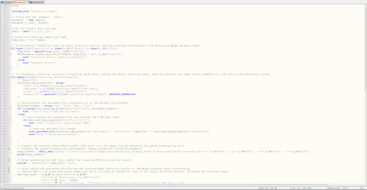
⭐ 📁 update.php
⭐ Include the class.php file.
⭐ Define the anomaly object of the _main class.
include_once "assets/class.php";// Define the new 'anomaly ' object:$anomaly = new _main();$anomaly->__init__($conn);
⭐ Obtain the current date and time.
⭐ Initiate the resulting image file name by adding the prediction date.
$date = date("Y_m_d_H_i_s");$img_file = "%s_".$date;⭐ If FireBeetle 2 ESP32-S3 transfers the object detection model results via GET query parameters, save the received information to the detections MySQL database table.
if(isset($_GET["results"]) && isset($_GET["class"]) && isset($_GET["x"])){ $img_file = sprintf($img_file, $_GET["class"]); if($anomaly->insert_new_results($date, $img_file.".jpg", $_GET["class"])){ echo "Detection Results Saved Successfully!"; }else{ echo "Database Error!"; }}⭐ If FireBeetle 2 ESP32-S3 transfers a resulting image via an HTTP POST request after running the object detection model:
⭐ Save the received raw image buffer (RGB565) as a TXT file to the detections folder.
⭐ Execute the rgb565_converter.py file with the built-in shell_exec function to convert the saved RGB565 buffer to a JPG file. While executing the Python code, pass the received bounding box measurements (via GET query parameters) as Python Arguments.
⭐ After generating the JPG file, remove the recently converted TXT file from the server.
⭐ After saving the received model detection results and the generated resulting image name to the detections database table successfully, send an SMS to the given user phone number via Twilio so as to notify the user, including the resulting image URL path.
if(!empty($_FILES["resulting_image"]['name'])){ // Image File: $received_img_properties = array( "name" => $_FILES["resulting_image"]["name"], "tmp_name" => $_FILES["resulting_image"]["tmp_name"], "size" => $_FILES["resulting_image"]["size"], "extension" => pathinfo($_FILES["resulting_image"]["name"], PATHINFO_EXTENSION) ); // Check whether the uploaded file's extension is in the allowed file formats. $allowed_formats = array('jpg', 'png', 'bmp', 'txt'); if(!in_array($received_img_properties["extension"], $allowed_formats)){ echo 'FILE => File Format Not Allowed!'; }else{ // Check whether the uploaded file size exceeds the 5 MB data limit. if($received_img_properties["size"] > 5000000){ echo "FILE => File size cannot exceed 5MB!"; }else{ // Save the uploaded file (image). move_uploaded_file($received_img_properties["tmp_name"], "./detections/".$img_file.".".$received_img_properties["extension"]); echo "FILE => Saved Successfully!"; } } // Convert the recently saved RGB565 buffer (TXT file) to a JPG image file by executing the rgb565_converter.py file. // Transmit the passed bounding box measurements (query parameters) as Python Arguments. $raw_convert = shell_exec('python "C:\Users\kutlu\New E\xampp\htdocs\mechanical_anomaly_detector\detections\rgb565_converter.py" --x='.$_GET["x"].' --y='.$_GET["y"].' --w='.$_GET["w"].' --h='.$_GET["h"]); print($raw_convert); // After generating the JPG file, remove the converted TXT file from the server. unlink("./detections/".$img_file.".txt"); // After saving the generated JPG file and the received model detection results to the MySQL database table successfully, // send an SMS to the given user phone number via Twilio in order to inform the user of the latest detection results, including the resulting image. $message_body = "⚠️🚨⚙️ Anomaly Detected ⚠️🚨⚙️" ."\n\r\n\r📌 Faulty Part: ".$_GET["class"] ."\n\r\n\r⏰ Date: ".$date ."\n\r\n\r🌐 🖼️ http://192.168.1.22/mechanical_anomaly_detector/detections/images/".$img_file.".jpg" ."\n\r\n\r📲 Please refer to the Android application to inspect the resulting image index."; $anomaly->Twilio_send_SMS($message_body);}⭐ 📁 results.php
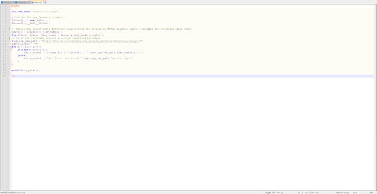
⭐ Include the class.php file.
⭐ Define the anomaly object of the _main class.
include_once "assets/class.php";// Define the new 'anomaly ' object:$anomaly = new _main();$anomaly->__init__($conn);
⭐ Fetch all model detection results and the associated resulting image file names from the detections database table in descending order.
⭐ Generate a comma-separated string list from the retrieved data records. If there are not enough data records to create a list of three elements, fill the list with default variables.
⭐ Then, print the generated string list.
$date=[]; $class=[]; $img_name=[];list($date, $class, $img_name) = $anomaly->get_model_results();// Print the retrieved results as a list separated by commas.$web_app_img_path = "http://192.168.1.22/mechanical_anomaly_detector/detections/images/";$data_packet = "";for($i=0;$i<3;$i++){ if(isset($date[$i])){ $data_packet .= $class[$i].",".$date[$i].",".$web_app_img_path.$img_name[$i].","; }else{ $data_packet .= "Not Found!,Not Found!,".$web_app_img_path."waiting.png,"; }}echo($data_packet);![]()
![]()
![]()
-
9Step 6.1: Converting the buffers transferred by FireBeetle 2 ESP32-S3 via POST requests to JPG files and obtaining the resulting bounding box measurements as Python Arguments
As explained earlier, FireBeetle 2 ESP32-S3 cannot modify resulting image buffers (RGB565) to draw bounding boxes generated by the object detection model directly. Therefore, I utilized the web application to process the resulting image buffers, convert them to JPG files, and add bounding boxes to the converted images.
I programmed a simple Python script to perform the mentioned operations. Since the Python script accepts parameters as Python Arguments, the web application passes the bounding box measurements received via GET query parameters effortlessly.
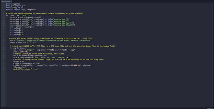
You can inspect the code for modifying RGB565 image buffers and passing Python Arguments below — rgb565_converter.py.
⭐ Include the required modules.
import argparsefrom glob import globimport numpy as npfrom PIL import Image, ImageDraw
⭐ Enable Python Arguments and acquire the bounding box measurements passed by the web application.
⭐ Obtain all the RGB565 buffer arrays transferred by FireBeetle 2 ESP32-S3 and saved as text (.txt) files in the detections folder.
⭐ Convert each retrieved RGB565 buffer (TXT file) to a JPG image file.
⭐ Then, modify the converted JPG file to draw the model bounding box by utilizing the passed measurements.
⭐ Finally, save the modified resulting image with the provided file name to the images folder under the detections folder.
if __name__ == '__main__': parser = argparse.ArgumentParser() parser.add_argument("--x", required=True, help="bounding box [X]") parser.add_argument("--y", required=True, help="bounding box [Y]") parser.add_argument("--w", required=True, help="bounding box [Width]") parser.add_argument("--h", required=True, help="bounding box [Height]") args = parser.parse_args() x = int(args.x) y = int(args.y) w = int(args.w) h = int(args.h) # Obtain all RGB565 buffer arrays transferred by FireBeetle 2 ESP32-S3 as text (.txt) files. path = "C:\\Users\\kutlu\\New E\\xampp\\htdocs\\mechanical_anomaly_detector\\detections" images = glob(path + "/*.txt") # Convert each RGB565 buffer (TXT file) to a JPG image file and save the generated image files to the images folder. for img in images: loc = path + "/images/" + img.split("\\")[8].split(".")[0] + ".jpg" size = (240,240) # RGB565 (uint16_t) to RGB (3x8-bit pixels, true color) raw = np.fromfile(img).byteswap(True) file = Image.frombytes('RGB', size, raw, 'raw', 'BGR;16', 0, 1) # Modify the converted RGB buffer (image) to draw the received bounding box on the resulting image. offset = 50 m_file = ImageDraw.Draw(file) m_file.rectangle([(x, y), (x+w+offset, y+h+offset)], outline=(225,255,255), width=3) file.save(loc) #print("Converted: " + loc)![]()
![]()
![]()
-
10Step 6.2: Setting and running the web application on LattePanda 3 Delta
Since I wanted to build a budget-friendly and accessible AIoT mechanical anomaly detector not dependent on cloud or hosting services, I decided to host my web application on LattePanda 3 Delta 864. Therefore, I needed to set up a LAMP web server.
LattePanda 3 Delta is a pocket-sized hackable computer that provides ultra performance with the Intel 11th-generation Celeron N5105 processor.
Plausibly, LattePanda 3 Delta can run the XAMPP application. So, it is effortless to create a server with a MariaDB database on LattePanda 3 Delta.
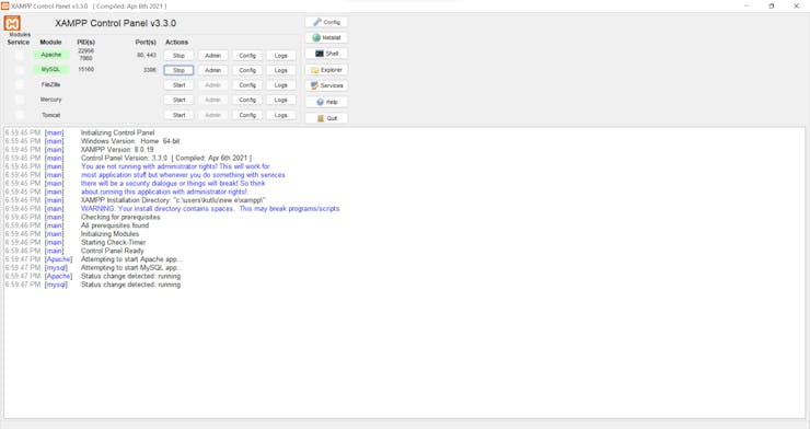
#️⃣ First of all, install and set up the XAMPP application.
#️⃣ Then, go to the XAMPP Control Panel and click the MySQL Admin button.
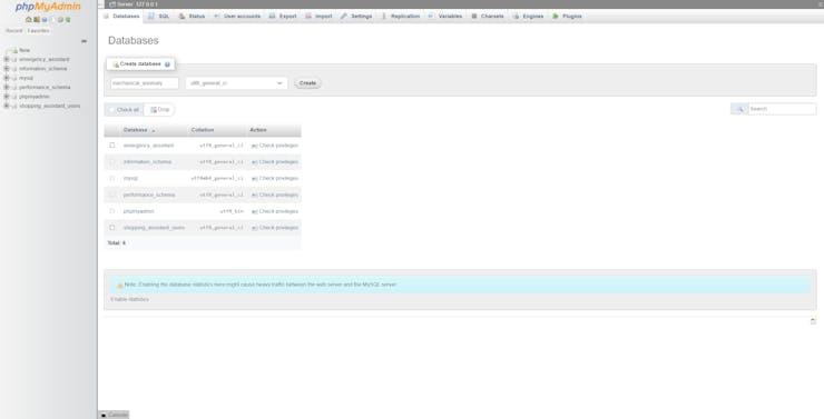
#️⃣ Once the phpMyAdmin tool pops up, create a new database named mechanical_anomaly.
![]()
![]()
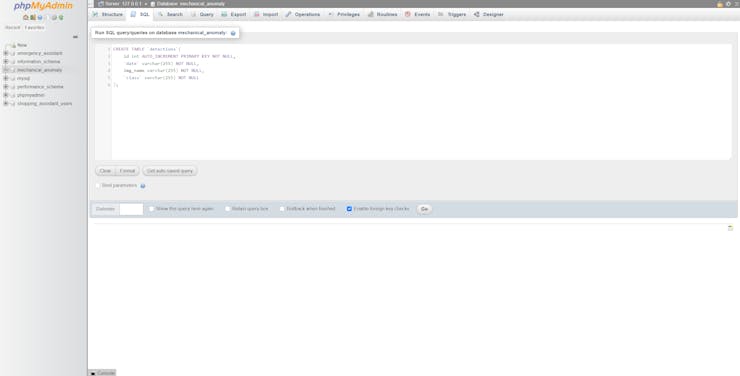
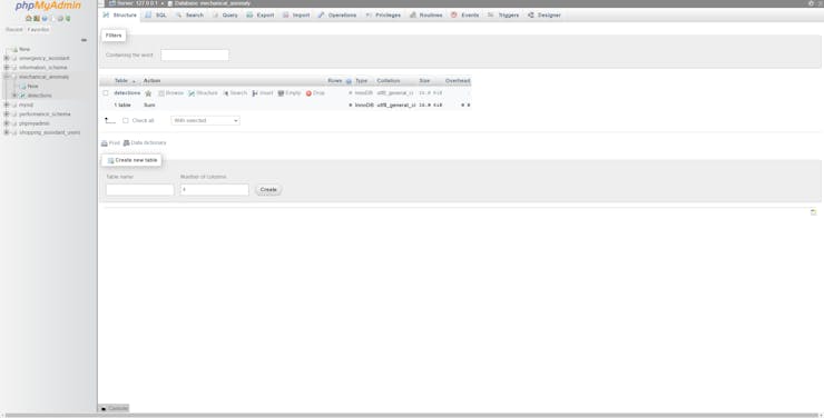
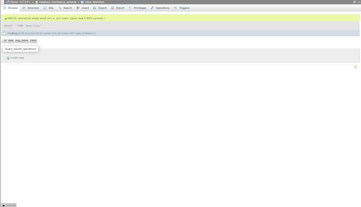
#️⃣ After adding the database successfully, go to the SQL section to create a MySQL database table named detections with the required data fields.
CREATE TABLE `detections`( id int AUTO_INCREMENT PRIMARY KEY NOT NULL, `date` varchar(255) NOT NULL, img_name varchar(255) NOT NULL, `class` varchar(255) NOT NULL);
![]()
![]()
![]()
Multi-Model AI-Based Mechanical Anomaly Detector
Apply sound data-based anomalous behavior detection, diagnose the root cause via object detection concurrently, and inform the user via SMS.


Discussions
Become a Hackaday.io Member
Create an account to leave a comment. Already have an account? Log In.