 kutluhan_aktar
-
11Step 7: Setting up FireBeetle 2 ESP32-S3 and Beetle ESP32-C3 on Arduino IDE
Since the Fermion IPS TFT display provides a microSD card module to read and write files on a microSD card, I decided to capture image samples with the built-in OV2640 camera on FireBeetle 2 ESP32-S3 and save them directly without applying any additional data transfer procedures.
I employed Beetle ESP32-C3 to communicate with the Android application over BLE to obtain the given user commands (for instance, the selected component class for image sample collection) and transfer audio-based neural network model detection results. Also, I utilized Beetle ESP32-C3 to send the BLE-transmitted commands to FireBeetle 2 ESP32-S3 via serial communication as a proxy.
Since I utilized Beetle ESP32-C3 in combination with FireBeetle 2 ESP32-S3, I needed to set both development boards on the Arduino IDE, install the required libraries, and configure some default settings before proceeding with the following steps.
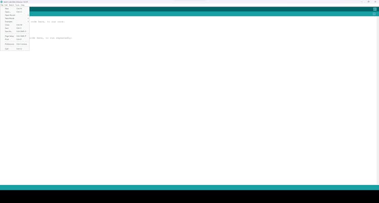
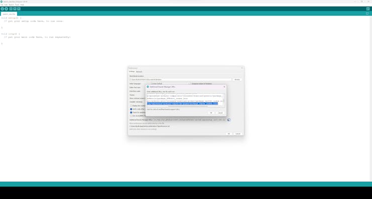
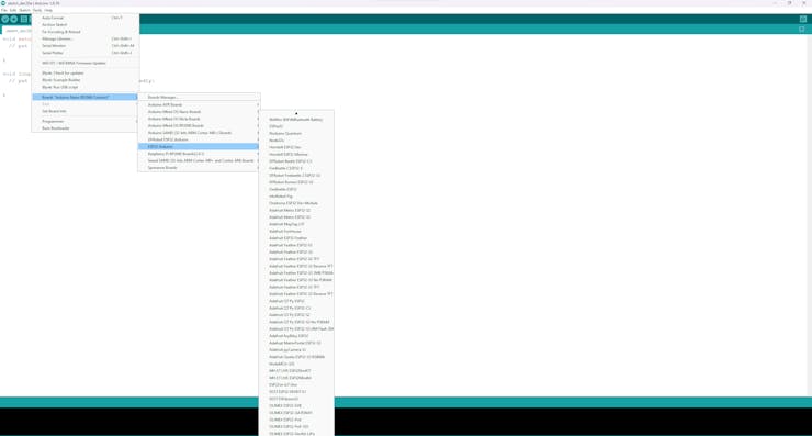
#️⃣ To add the FireBeetle 2 ESP32-S3 board package to the Arduino IDE, navigate to File ➡ Preferences and paste the URL below under Additional Boards Manager URLs.
https://raw.githubusercontent.com/espressif/arduino-esp32/gh-pages/package_esp32_index.json
![]()
![]()
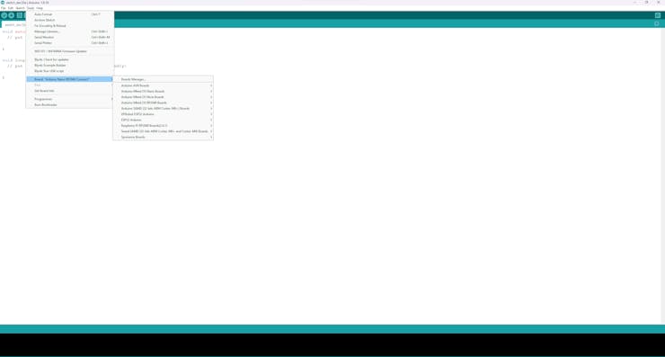
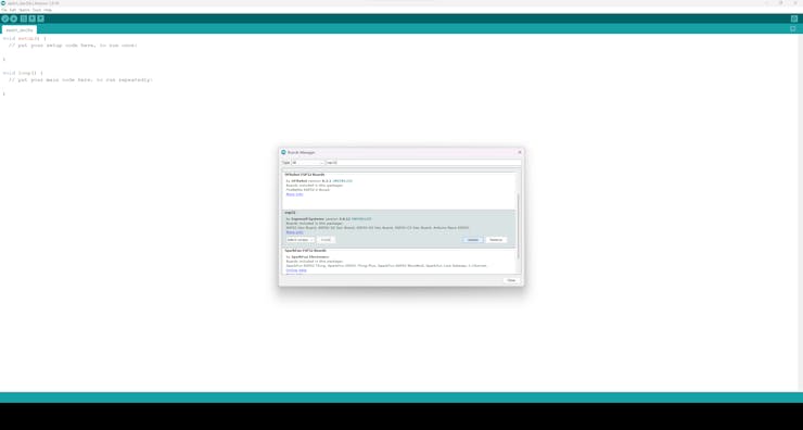
#️⃣ Then, to install the required core, navigate to Tools ➡ Board ➡ Boards Manager and search for esp32.
![]()
![]()
#️⃣ After installing the core, navigate to Tools ➡ Board ➡ ESP32 Arduino and select DFRobot FireBeetle 2 ESP32-S3.
![]()
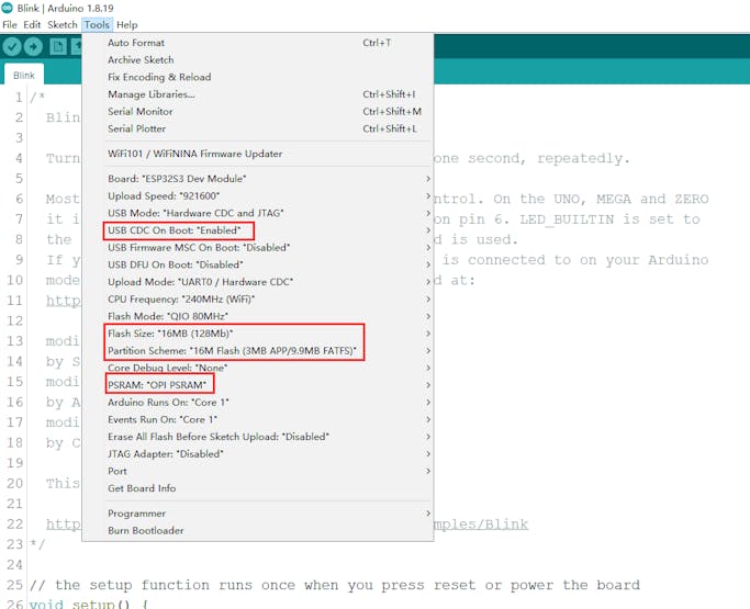
#️⃣ To ensure the FireBeetle 2 ESP32-S3 integrated hardware functions work faultlessly, configure some default ESP32 board settings on the Arduino IDE.
- USB CDC On Boot: "Enabled"
- Flash Size: "16MB (128Mb)"
- Partition Scheme: "16M Flash (3MB APP/9.9MB FATFS)"
- PSRAM: "OPI PSRAM"
![]()
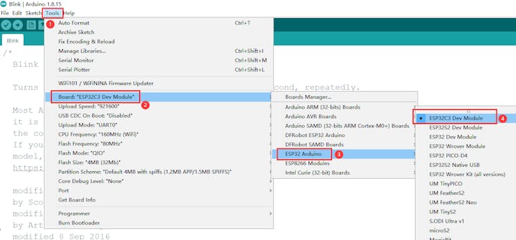
#️⃣ To add the Beetle ESP32-C3 board package to the Arduino IDE, after following the steps above, navigate to Tools ➡ Board ➡ ESP32 Arduino and select ESP32C3 Dev Module.
![]()
#️⃣ Download and inspect the required libraries for the Fermion IPS TFT display, the Fermion I2S MEMS microphone, and the AXP313A power output:
DFRobot_GDL | Download
DFRobot_MSM261 | Download
DFRobot_AXP313A | Download
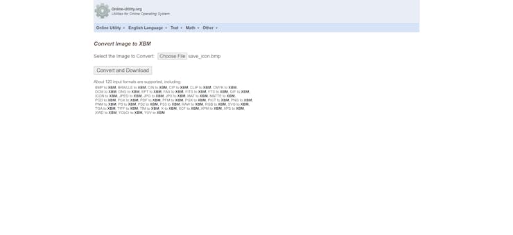
#️⃣ To be able to display images (icons) on the Fermion TFT display, convert image files to a C/C++ array format. I decided to utilize an online converter to save image files in the XBM format, a monochrome bitmap format in which data is stored as a C data array.
#️⃣ Then, save all the converted C arrays in the XBM format to the logo.h file.
![]()
![]()
-
12Step 8: Recording sound-based anomaly samples via the Android application
As explained earlier, Beetle ESP32-C3 does not have a secondary storage option for audio sample collection via the onboard I2S microphone. Therefore, I decided to capitalize on the phone microphone and internal storage via the Android application while recording audio samples.
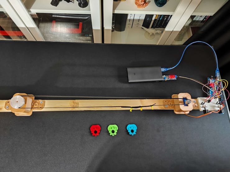
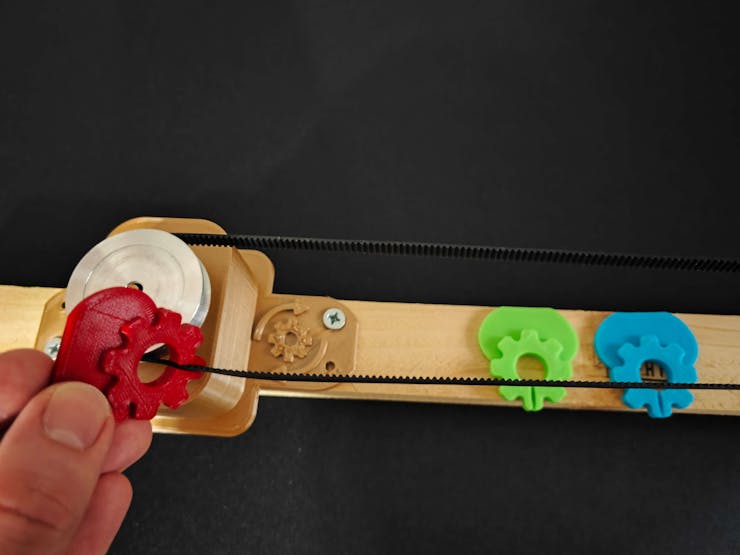
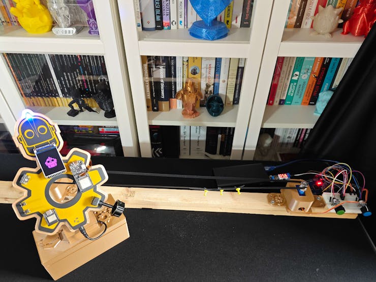
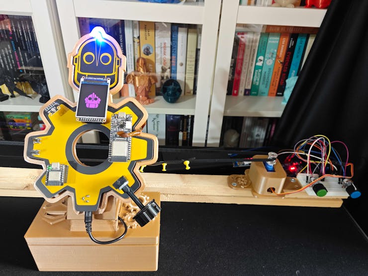
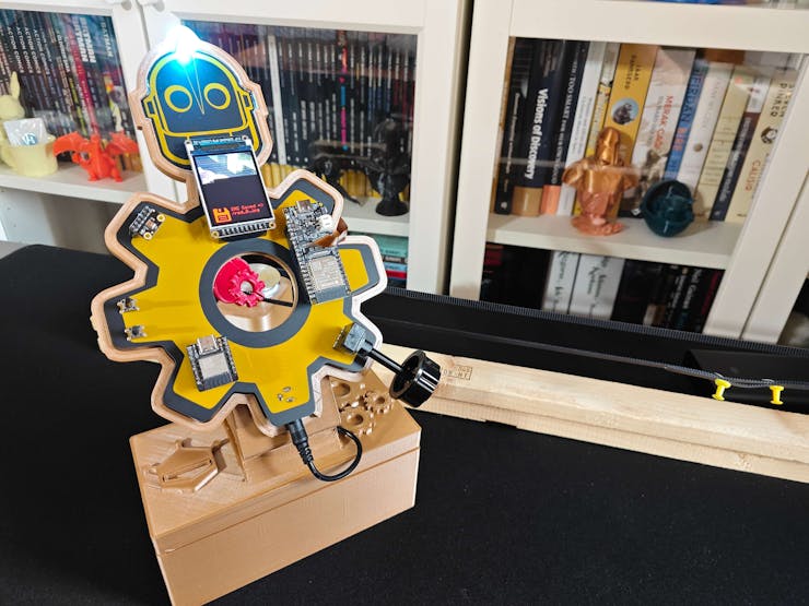
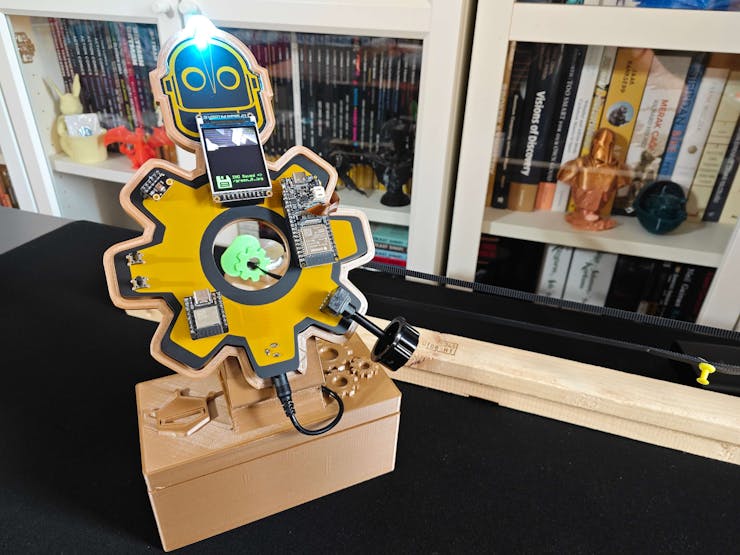
#️⃣ First of all, I utilized the specialized components (parts) to manifest a mechanical anomaly by shifting the timing belt and jamming the GT2 60T pulley.
#️⃣ Due to the fact that the pulley is jammed, the servo motor starts vibrating and humming, which demonstrates an audio-based mechanical anomaly.
![]()
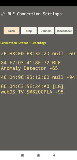
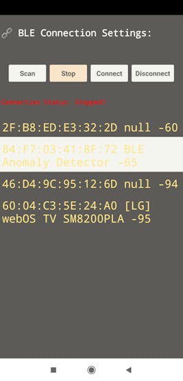
⚙️⚠️🔊📲 After installing the Mechanical Anomaly Detector application, open the user interface and search for the peripheral device named BLE Anomaly Detector to communicate with Beetle ESP32-C3 over BLE.
⚙️⚠️🔊📲 If the Scan button is pressed, the Android application searches for compatible peripheral devices and shows their address information as a list.
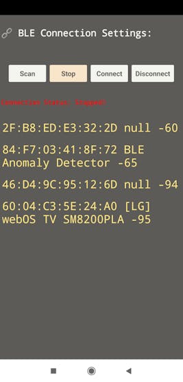
⚙️⚠️🔊📲 If the Stop button is pressed, the Android application suspends the scanning process.
![]()
![]()
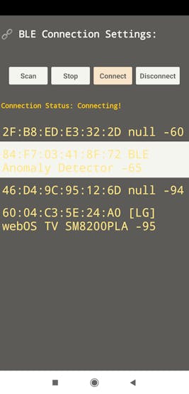
⚙️⚠️🔊📲 If the Connect button is pressed, the Android application attempts to connect to the selected peripheral device.
![]()
![]()
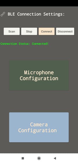
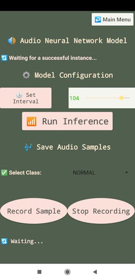
⚠️🔊📲 As the Android application connects to Beetle ESP32-C3 over BLE successfully, the application shows two main configuration options on the interface:
- Microphone Configuration
- Camera Configuration
![]()
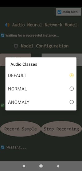
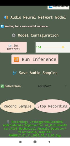
⚙️⚠️🔊📲 To record a new audio sample, go to the microphone configuration section and select an audio-based anomaly class via the spinner:
- NORMAL
- ANOMALY
![]()
![]()
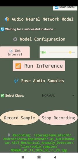
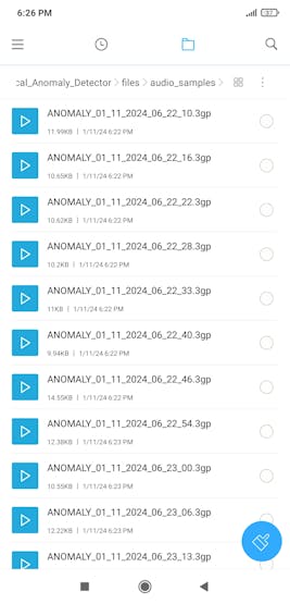
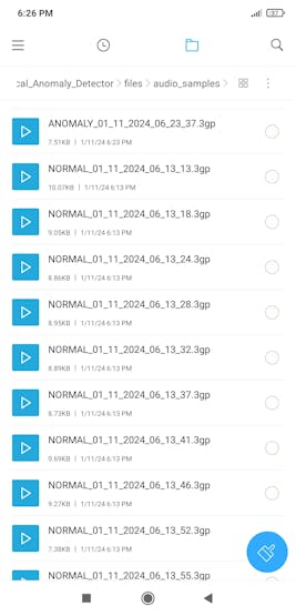
⚙️⚠️🔊📲 After selecting an audio-based anomaly class, click the Record Sample button to start recording a new audio sample.
⚙️⚠️🔊📲 The Android application adds the current date & time to the file name of the recording audio sample and displays its internal storage path.
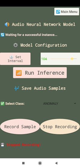
⚙️⚠️🔊📲 When the Stop Recording button is pressed, the Android application halts recording and saves the currently recorded sample of the selected class to the internal storage.
- NORMAL_01_11_2024_06_13_13.3gp
- ANOMALY_01_11_2024_06_22_46.3gp
![]()
![]()
![]()
![]()
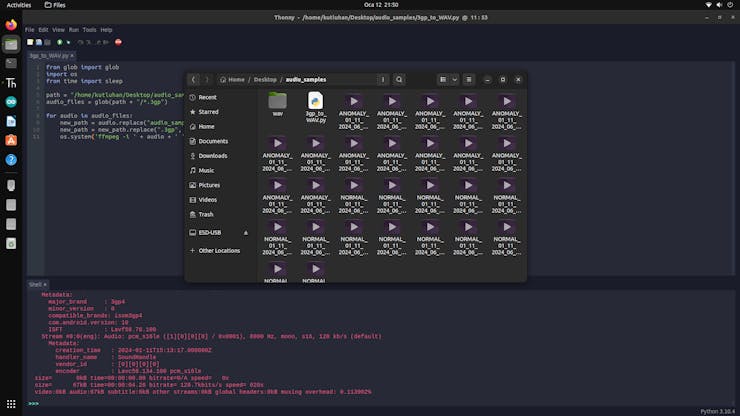
⚙️⚠️🔊📲 Since the Android application can only access the ASD (app-specific dir) without additional permission, it saves the audio samples (3GP files) to the audio_samples folder in the root directory of the application.
⚙️⚠️🔊📲 The Android application saves 3GP audio samples since the built-in sound recorder object of the MIT APP Inventor only supports the 3GP format.
![]()
![]()
After conducting tests with the specialized components (parts) to manifest mechanical deviations and collecting audio-based anomaly samples via the Android application, I acquired a valid and notable data set for the neural network model (audio classification).
-
13Step 9: Capturing faulty component (part) images w/ the built-in OV2640 camera
After setting FireBeetle 2 ESP32-S3 and Beetle ESP32-C3 on the Arduino IDE, I programmed FireBeetle 2 ESP32-S3 to communicate with Beetle ESP32-C3 to obtain the commands transferred by the Android application via serial communication, capture raw image buffers, convert the captured buffers to JPG files, and save them as samples to the microSD card on the Fermion TFT display.
Since I needed to add color-coded component classes as labels to the file names of each sample while collecting data to create a valid data set for the object detection model, I decided to utilize the Android application to transmit commands to Beetle ESP32-C3 over BLE. Then, I utilized Beetle ESP32-C3 as a proxy to transfer the passed commands to FireBeetle 2 ESP32-S3 via serial communication so as to capture an image sample with the incrementing sample number and save it to the microSD card with the selected class. Despite the fact that the Android application supports remote image sample collection, I decided to provide the user to collect image samples onboard (manually) considering the extreme operating conditions. In this regard, I connected a long-shaft potentiometer and two control buttons to Beetle ESP32-C3 in order to let the user transfer commands to FireBeetle 2 ESP32-S3 via serial communication manually.
Since different UUID sets, a 128-bit value used to specifically identify an object or entity, are required to assign services and characteristics for a stable BLE connection, it is crucial to generate individualized UUIDs with an online UUID generator. After generating your UUIDs, you can update the given UUIDs, as shown below.
As explained earlier, this mechanical anomaly detector is composed of two separate development boards — FireBeetle 2 ESP32-S3 and Beetle ESP32-C3 — performing interconnected features for data collection and running neural network models. Therefore, the described code snippets are parts of separate code files. Please refer to the code files to inspect all interconnected functions in detail.
📁 AIoT_Mechanical_Anomaly_Detector_Audio.ino
⭐ Include the required libraries.
#include <Arduino.h>#include <ArduinoBLE.h>#include <driver/i2s.h>
⭐ Create the BLE service and data characteristics. Then, allow the remote device (central) to read, write, and notify.
BLEService Anomaly_Detector("e1bada10-a728-44c6-a577-6f9c24fe980a");// Create data characteristics and allow the remote device (central) to write, read, and notify:BLEFloatCharacteristic audio_detected_Characteristic("e1bada10-a728-44c6-a577-6f9c24fe984a", BLERead | BLENotify);BLEByteCharacteristic selected_img_class_Characteristic("e1bada10-a728-44c6-a577-6f9c24fe981a", BLERead | BLEWrite);BLEByteCharacteristic given_command_Characteristic("e1bada10-a728-44c6-a577-6f9c24fe983a", BLERead | BLEWrite);⭐ Initiate the serial communication between Beetle ESP32-C3 and FireBeetle 2 ESP32-S3.
Serial1.begin(9600, SERIAL_8N1, /*RX=*/20, /*TX=*/21);
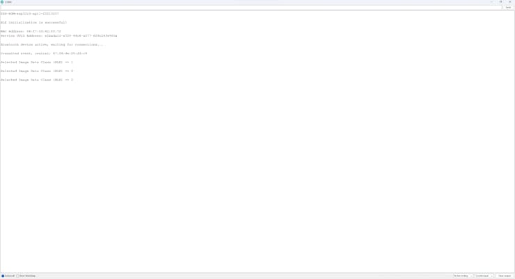
⭐ Check the BLE initialization status and print the Beetle ESP32-C3 address information on the serial monitor.
while(!BLE.begin()){ Serial.println("BLE initialization is failed!"); } Serial.println("\nBLE initialization is successful!\n"); // Print this peripheral device's address information: Serial.print("MAC Address: "); Serial.println(BLE.address()); Serial.print("Service UUID Address: "); Serial.println(Anomaly_Detector.uuid()); Serial.println();⭐ Set the local name (BLE Anomaly Detector) for Beetle ESP32-C3 and the UUID for the advertised (transmitted) service.
⭐ Add the given data characteristics to the service. Then, add the given service to the advertising device.
⭐ Assign event handlers for connected and disconnected devices to/from Beetle ESP32-C3.
⭐ Assign event handlers for the data characteristics modified (written) by the central device (via the Android application). In this regard, obtain the transferred (written) data packets from the Android application over BLE.
⭐ Finally, start advertising (broadcasting) information.
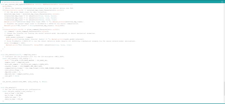
BLE.setLocalName("BLE Anomaly Detector"); // Set the UUID for the service this peripheral advertises: BLE.setAdvertisedService(Anomaly_Detector); // Add the given data characteristics to the service: Anomaly_Detector.addCharacteristic(audio_detected_Characteristic); Anomaly_Detector.addCharacteristic(selected_img_class_Characteristic); Anomaly_Detector.addCharacteristic(given_command_Characteristic); // Add the given service to the advertising device: BLE.addService(Anomaly_Detector); // Assign event handlers for connected and disconnected devices to/from this peripheral: BLE.setEventHandler(BLEConnected, blePeripheralConnectHandler); BLE.setEventHandler(BLEDisconnected, blePeripheralDisconnectHandler); // Assign event handlers for the data characteristics modified (written) by the central device (via the Android application). // In this regard, obtain the transferred (written) data packets from the Android application over BLE. selected_img_class_Characteristic.setEventHandler(BLEWritten, get_central_BLE_updates); given_command_Characteristic.setEventHandler(BLEWritten, get_central_BLE_updates); // Start advertising: BLE.advertise(); Serial.println("Bluetooth device active, waiting for connections...");⭐ If the long-shaft potentiometer value is altered from its previous value, change the selected component class depending on the current potentiometer value for image sample collection. Then, adjust the RGB LED according to the assigned color code of the selected class.
int current_pot_value = map(analogRead(potentiometer_pin), 360, 4096, 0, 10); delay(100); if(abs(current_pot_value-pre_pot_value) > 1){ if(current_pot_value == 0){ adjustColor(true, true, true); } if(current_pot_value > 0 && current_pot_value <= 3){ adjustColor(true, false, false); selected_img_class = 0; } if(current_pot_value > 3 && current_pot_value <= 7){ adjustColor(false, true, false); selected_img_class = 1; } if(current_pot_value > 7){ adjustColor(false, false, true); selected_img_class = 2; } pre_pot_value = current_pot_value; }⭐ If the control button (A) is pressed, transfer the given image class (selected manually or via BLE) to FireBeetle 2 ESP32-S3 via serial communication.
⭐ If the control button (B) is pressed, transfer the Run Inference command to FireBeetle 2 ESP32-S3 via serial communication.
if(!digitalRead(control_button_1)){ Serial1.print("IMG_Class=" + String(selected_img_class)); delay(500); adjustColor(false, true, true); } if(!digitalRead(control_button_2)){ Serial1.print("Run Inference"); delay(500); adjustColor(true, false, true); }⭐ In the get_central_BLE_updates function:
⭐ Obtain the recently transmitted data packets from the central device over BLE via the Android application.
⭐ If the user transmits a component class via the Android application, transfer the passed image class to FireBeetle 2 ESP32-S3 via serial communication for image sample collection.
⭐ If the user sends a device command via the Android application, decode the received data packet to acquire the transmitted command (number).
⭐ From 30 to 120, change the interval for running the neural network model (audio classification) to detect sound-based mechanical anomalies.
⭐ Greater than 130, transfer the Run Inference command to FireBeetle 2 ESP32-S3 via serial communication.
void get_central_BLE_updates(BLEDevice central, BLECharacteristic characteristic){ delay(500); // Obtain the recently transferred data packets from the central device over BLE. if(characteristic.uuid() == selected_img_class_Characteristic.uuid()){ // Get the given image class for data collection. selected_img_class = selected_img_class_Characteristic.value(); if(selected_img_class == 0) adjustColor(true, false, false); if(selected_img_class == 1) adjustColor(false, true, false); if(selected_img_class == 2) adjustColor(false, false, true); Serial.print("\nSelected Image Data Class (BLE) => "); Serial.println(selected_img_class); // Transfer the passed image class to FireBeetle 2 ESP32-S3 via serial communication. Serial1.print("IMG_Class=" + String(selected_img_class)); delay(500); } if(characteristic.uuid() == given_command_Characteristic.uuid()){ int command = given_command_Characteristic.value(); // Change the interval for running the neural network model (microphone) to detect mechanical anomalies. if(command < 130){ audio_model_interval = command; Serial.print("\nGiven Model Interval (Audio) => "); Serial.println(audio_model_interval); // Force FireBeetle 2 ESP32-S3 to run the object detection model despite not detecting a mechanical anomaly via the neural network model (microphone). }else if(command > 130){ Serial1.print("Run Inference"); delay(500); adjustColor(true, false, true); } }}![]()
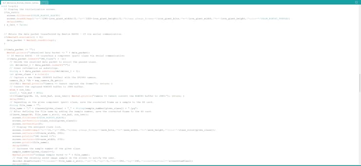
📁 AIoT_Mechanical_Anomaly_Detector_Camera.ino
⭐ Include the required libraries.
#include <WiFi.h>#include "esp_camera.h"#include "FS.h"#include "SD.h"#include "DFRobot_GDL.h"#include "DFRobot_Picdecoder_SD.h"
⭐ Add the logo.h file, consisting of all the converted icons (C arrays) to be shown on the Fermion TFT LCD display.
#include "logo.h"
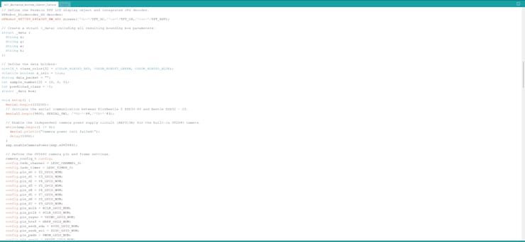
⭐ Define the pin configuration of the built-in OV2640 camera on FireBeetle 2 ESP32-S3.
#define PWDN_GPIO_NUM -1#define RESET_GPIO_NUM -1#define XCLK_GPIO_NUM 45#define SIOD_GPIO_NUM 1#define SIOC_GPIO_NUM 2#define Y9_GPIO_NUM 48#define Y8_GPIO_NUM 46#define Y7_GPIO_NUM 8#define Y6_GPIO_NUM 7#define Y5_GPIO_NUM 4#define Y4_GPIO_NUM 41#define Y3_GPIO_NUM 40#define Y2_GPIO_NUM 39#define VSYNC_GPIO_NUM 6#define HREF_GPIO_NUM 42#define PCLK_GPIO_NUM 5
⭐ Since FireBeetle 2 ESP32-S3 has an independent camera power supply circuit, initiate the AXP313A power output when using the camera.
#include "DFRobot_AXP313A.h"DFRobot_AXP313A axp;
⭐ Define the Fermion TFT LCD display object and the integrated JPG decoder for this screen.
DFRobot_Picdecoder_SD decoder;DFRobot_ST7789_240x320_HW_SPI screen(/*dc=*/TFT_DC,/*cs=*/TFT_CS,/*rst=*/TFT_RST);
⭐ Initiate the serial communication between FireBeetle 2 ESP32-S3 and Beetle ESP32-C3.
Serial1.begin(9600, SERIAL_8N1, /*RX=*/44,/*TX=*/43);
⭐ Enable the independent camera power supply circuit (AXP313A) for the built-in OV2640 camera.
while(axp.begin() != 0){ Serial.println("Camera power init failed!"); delay(1000); } axp.enableCameraPower(axp.eOV2640);⭐ Assign the configured pins of the built-in OV2640 camera and define the frame (buffer) settings.
camera_config_t config; config.ledc_channel = LEDC_CHANNEL_0; config.ledc_timer = LEDC_TIMER_0; config.pin_d0 = Y2_GPIO_NUM; config.pin_d1 = Y3_GPIO_NUM; config.pin_d2 = Y4_GPIO_NUM; config.pin_d3 = Y5_GPIO_NUM; config.pin_d4 = Y6_GPIO_NUM; config.pin_d5 = Y7_GPIO_NUM; config.pin_d6 = Y8_GPIO_NUM; config.pin_d7 = Y9_GPIO_NUM; config.pin_xclk = XCLK_GPIO_NUM; config.pin_pclk = PCLK_GPIO_NUM; config.pin_vsync = VSYNC_GPIO_NUM; config.pin_href = HREF_GPIO_NUM; config.pin_sscb_sda = SIOD_GPIO_NUM; config.pin_sscb_scl = SIOC_GPIO_NUM; config.pin_pwdn = PWDN_GPIO_NUM; config.pin_reset = RESET_GPIO_NUM; config.xclk_freq_hz = 10000000; // Set XCLK_FREQ_HZ as 10KHz to avoid the EV-VSYNC-OVF error. config.frame_size = FRAMESIZE_240X240; // FRAMESIZE_QVGA (320x240), FRAMESIZE_SVGA config.pixel_format = PIXFORMAT_RGB565; // PIXFORMAT_JPEG config.grab_mode = CAMERA_GRAB_LATEST; // CAMERA_GRAB_WHEN_EMPTY config.fb_location = CAMERA_FB_IN_PSRAM; config.jpeg_quality = 10; config.fb_count = 2; // for CONFIG_IDF_TARGET_ESP32S3
⭐ Initialize the OV2640 camera.
esp_err_t err = esp_camera_init(&config); if (err != ESP_OK) { Serial.printf("Camera init failed with error 0x%x", err); return; }⭐ Initialize the Fermion TFT LCD display. Set the screen rotation upside-down (2) due to the screen's PCB placement.
screen.begin(); screen.setRotation(2); delay(1000);
⭐ Initialize the microSD card module on the Fermion TFT LCD display.
while(!SD.begin(SD_CS_PIN)){ Serial.println("SD Card => No module found!"); delay(200); return; }⭐ When requested, show the initialization interface with the Iron Giant icon on the Fermion TFT display.
if(s_init){ screen.fillScreen(COLOR_RGB565_BLACK); screen.drawXBitmap(/*x=*/(240-iron_giant_width)/2,/*y=*/(320-iron_giant_height)/2,/*bitmap gImage_Bitmap=*/iron_giant_bits,/*w=*/iron_giant_width,/*h=*/iron_giant_height,/*color=*/COLOR_RGB565_PURPLE); delay(1000); } s_init = false;⭐ Obtain the data packet transferred by Beetle ESP32-C3 via serial communication.
if(Serial1.available() > 0){ data_packet = Serial1.readString(); }⭐ If Beetle ESP32-C3 transfers the selected component (part) class (adjusted manually or received via the Android application) via serial communication:
⭐ Decode the received data packet as substrings to acquire the passed component class.
⭐ Capture a new frame (RGB565 buffer) with the onboard OV2640 camera.
⭐ Convert the captured RGB565 buffer to a JPEG buffer by executing the built-in frame2jpg function.
⭐ Depending on the passed component (part) class:
⭐ Generate the file name with the current sample number of the passed class.
⭐ Save the converted frame as an image sample to the microSD card.
⭐ Notify the user on the Fermion TFT LCD display by displaying the assigned class icon.
⭐ Increase the sample number of the passed class.
⭐ Then, draw the recently saved image sample on the screen to ensure the sample quality.
⭐ Finally, release the image buffers.
if(data_packet != ""){ Serial.println("\nReceived Data Packet => " + data_packet); // If Beetle ESP32 - C3 transfers a component (part) class via serial communication: if(data_packet.indexOf("IMG_Class") > -1){ // Decode the received data packet to elicit the passed class. int delimiter_1 = data_packet.indexOf("="); // Glean information as substrings. String s = data_packet.substring(delimiter_1 + 1); int given_class = s.toInt(); // Capture a new frame (RGB565 buffer) with the OV2640 camera. camera_fb_t *fb = esp_camera_fb_get(); if(!fb){ Serial.println("Camera => Cannot capture the frame!"); return; } // Convert the captured RGB565 buffer to JPEG buffer. size_t con_len; uint8_t *con_buf = NULL; if(!frame2jpg(fb, 10, &con_buf, &con_len)){ Serial.println("Camera => Cannot convert the RGB565 buffer to JPEG!"); return; } delay(500); // Depending on the given component (part) class, save the converted frame as a sample to the SD card. String file_name = ""; file_name = "/" + classes[given_class] + "_" + String(sample_number[given_class]) + ".jpg"; // After defining the file name by adding the sample number, save the converted frame to the SD card. if(save_image(SD, file_name.c_str(), con_buf, con_len)){ screen.fillScreen(COLOR_RGB565_BLACK); screen.setTextColor(class_color[given_class]); screen.setTextSize(2); // Display the assigned class icon. screen.drawXBitmap(/*x=*/10,/*y=*/250,/*bitmap gImage_Bitmap=*/save_bits,/*w=*/save_width,/*h=*/save_height,/*color=*/class_color[given_class]); screen.setCursor(20+save_width, 255); screen.println("IMG Saved =>"); screen.setCursor(20+save_width, 275); screen.println(file_name); delay(1000); // Increase the sample number of the given class. sample_number[given_class]+=1; Serial.println("\nImage Sample Saved => " + file_name); // Draw the recently saved image sample on the screen to notify the user. decoder.drawPicture(/*filename=*/file_name.c_str(),/*sx=*/0,/*sy=*/0,/*ex=*/240,/*ey=*/240,/*screenDrawPixel=*/screenDrawPixel); delay(1000); }else{ screen.fillScreen(COLOR_RGB565_BLACK); screen.setTextColor(class_color[given_class]); screen.setTextSize(2); screen.drawXBitmap(/*x=*/10,/*y=*/250,/*bitmap gImage_Bitmap=*/save_bits,/*w=*/save_width,/*h=*/save_height,/*color=*/class_color[given_class]); screen.setCursor(20+save_width, 255); screen.println("SD Card =>"); screen.setCursor(20+save_width, 275); screen.println("File Error!"); delay(1000); } // Release the image buffers. free(con_buf); esp_camera_fb_return(fb); ...⭐ In the save_image function:
⭐ Create a new file with the given file name on the microSD card.
⭐ Save the given image buffer to the generated file on the microSD card.
bool save_image(fs::FS &fs, const char *file_name, uint8_t *data, size_t len){ // Create a new file on the SD card. volatile boolean sd_run = false; File file = fs.open(file_name, FILE_WRITE); if(!file){ Serial.println("SD Card => Cannot create file!"); return sd_run; } // Save the given image buffer to the created file on the SD card. if(file.write(data, len) == len){ Serial.printf("SD Card => IMG saved: %s\n", file_name); sd_run = true; }else{ Serial.println("SD Card => Cannot save the given image!"); } file.close(); return sd_run; }![]()
![]()
-
14Step 9.1: Saving the captured images as samples via the Android application
In any Bluetooth® Low Energy (also referred to as Bluetooth® LE or BLE) connection, devices can have one of these two roles: the central and the peripheral. A peripheral device (also called a client) advertises or broadcasts information about itself to devices in its range, while a central device (also called a server) performs scans to listen for devices broadcasting information. You can get more information regarding BLE connections and procedures, such as services and characteristics, from here.
To avoid latency or packet loss while advertising (transmitting) audio-based model detection results and receiving data packets from the Android application over BLE, I utilized an individual float data characteristic for the advertised information and byte data characteristics for the incoming information.
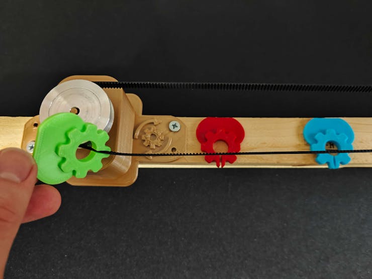
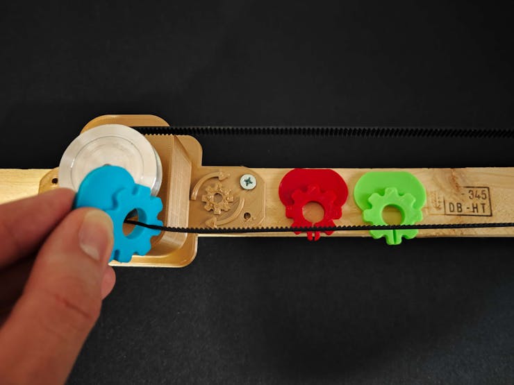
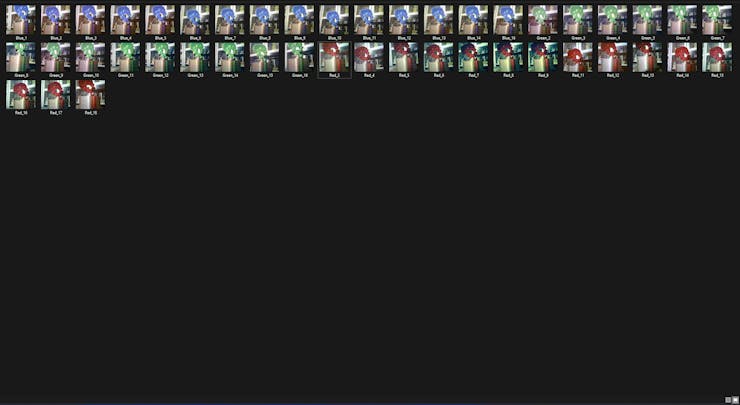
#️⃣ As explained earlier, I designed three specialized components (color-coded) representing the defective parts causing mechanical anomalies in a production line.
#️⃣ I conducted additional tests with each color-coded component to construct a valid image data set for the object detection model.
![]()
![]()
![]()
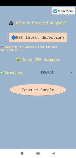
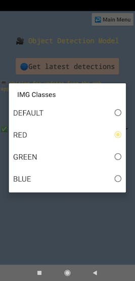
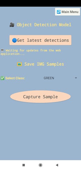
⚙️⚠️🔊📲 To select a component (part) class on the Android application, go to the camera configuration section.
⚙️⚠️🔊📲 After selecting a component class via the spinner, the Android application transmits the selected class to Beetle ESP32-C3 over BLE when the user clicks the Capture Sample button.
⚙️⚠️🔊📲 As Beetle ESP32-C3 receives the transmitted class over BLE, it sends the passed class to FireBeetle 2 ESP32-S3 via serial communication for image sample collection.
![]()
![]()
![]()
![]()
⚙️⚠️🔊📲 Although the Android application lets the user capture image samples remotely, Beetle ESP32-C3 supports selecting a component class by changing the current potentiometer value by hand.
⚙️⚠️🔊📲 When the user presses the control button (A), Beetle ESP32-C3 sends the manually selected class to FireBeetle 2 ESP32-S3 via serial communication for image sample collection.
![]()
![]()
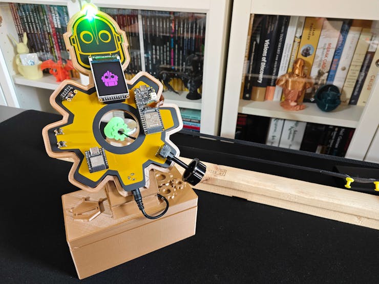
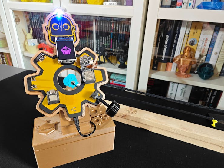
⚙️⚠️🔊📲 When a component class is selected manually or via the Android application, Beetle ESP32-C3 adjusts the RGB LED according to the assigned color code of the selected class.
- Red
- Green
- Blue
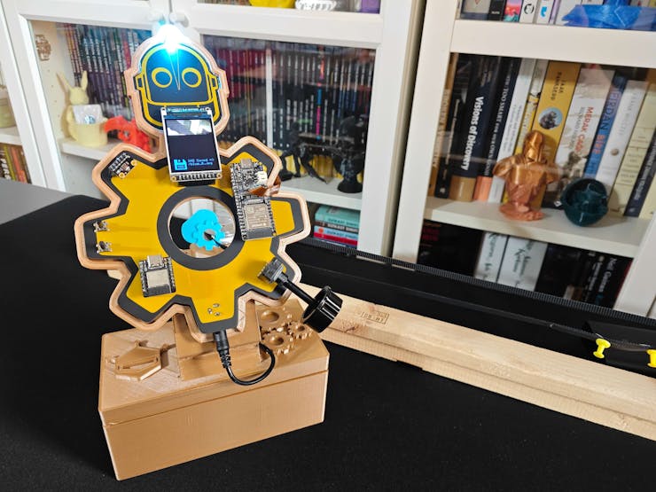
⚙️⚠️🔊📲 After FireBeetle 2 ESP32-S3 receives the selected class from Beetle ESP32-C3 via serial communication, it captures an image sample of the passed class via the built-in OV2640 camera and saves the captured sample with the incremented sample number of the passed class via the built-in microSD card module on the Fermion TFT display.
- Red_6.jpg
- Green_8.jpg
- Blue_12.jpg
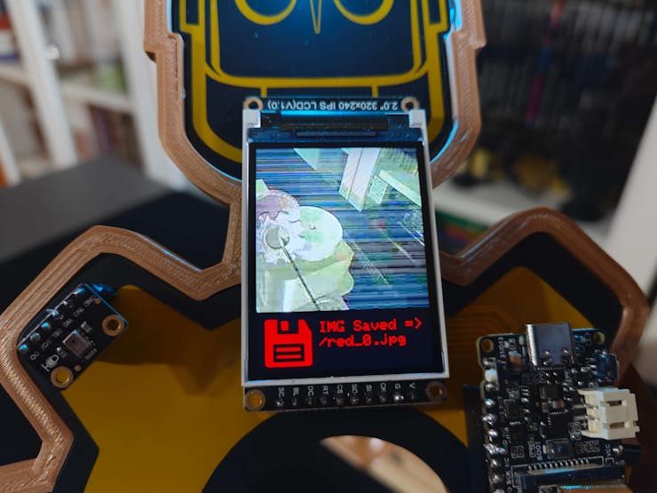
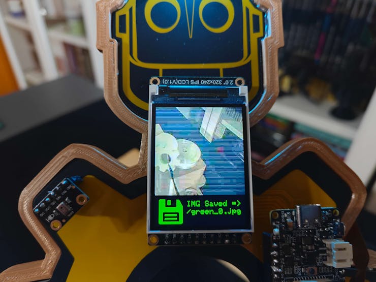
⚙️⚠️🔊📲 After saving an image sample successfully, FireBeetle 2 ESP32-S3 shows the recently saved image sample (JPG file) and the Saved Icon with the associated class color on the TFT display so as to inform the user of the sample quality.
![]()
![]()
![]()
![]()
![]()
![]()
![]()
![]()
⚙️⚠️🔊📲 Also, Beetle ESP32-C3 prints progression notifications on the serial monitor for debugging.
![]()
After collecting image samples of faulty components (color-coded) manifesting mechanical anomalies, I constructed a valid and notable image data set for the object detection model.
![]()
-
15Step 10: Building a neural network model with Edge Impulse
As explained earlier, I built a basic frequency-controlled apparatus (the X-axis timing belt system) to demonstrate mechanical deviations since I did not have the resources to conduct experiments in an industrial plant.
Then, I utilized the specialized components (3D-printed) to restrict the timing belt movements to engender mechanical anomalies. While recording audio samples for audio classification, I simply differentiate the samples with the current operation status:
- normal
- anomaly
When I completed collecting audio samples via the Android application, I started to work on my artificial neural network model (ANN) to detect sound-based mechanical anomalies before diagnosing the root cause of the manifested deviation.
Since Edge Impulse supports almost every microcontroller and development board due to its model deployment options, I decided to utilize Edge Impulse to build my artificial neural network model. Also, Edge Impulse makes scaling embedded ML applications easier and faster for edge devices such as Beetle ESP32-C3.
Furthermore, Edge Impulse provides the required tools for inspecting audio samples, slicing them into smaller windows, and modifying windows to extract features. Although Edge Impulse supports various audio formats (WAV, MP4, etc.), it does not support the 3GP format yet. Therefore, I needed to follow the steps below to format my data set so as to train my neural network model for audio classification accurately:
- Data Formatting
- Data Labeling
As explained in the following step, I programmed a simple Python script to convert the 3GP audio samples recorded by the Android application to the WAV format compatible with Edge Impulse. Nevertheless, you can utilize an online converter for the file conversion while constructing your data set for simplicity.
Plausibly, Edge Impulse allows building predictive models optimized in size and accuracy exceptionally and deploying the trained model as an Arduino library. Therefore, after formatting and preprocessing my data set, I was able to build a valid neural network model for audio classification to detect sound-based mechanical anomalies and run the model on Beetle ESP32-C3 without any additional requirements.
You can inspect my neural network model on Edge Impulse as a public project.
-
16Step 10.1: Converting the recorded 3GP audio samples to WAV
Since Edge Impulse does not support audio samples in the 3GP format, I needed to convert my audio samples to the officially supported WAV format for audio classification.
Even though there are various methods to convert audio files, including online converters, I decided to program a simple Python script (3gp_to_WAV.py) to modify my samples since it might be hindering to employ online tools for constructing large data sets.
Since I employed the ffmpeg module for the file conversion, I needed to run my Python script on a Linux operating system. Thankfully, I have a secondary Ubuntu operating system installed on LattePanda 3 Delta. Therefore, I booted into Ubuntu and started converting my audio samples effortlessly.
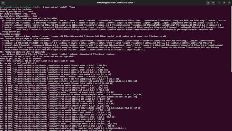
#️⃣ First of all, install the ffmpeg module on Ubuntu.
sudo apt-get install ffmpeg
![]()
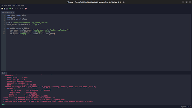
📁 In the 3gp_to_WAV.py file:
⭐ Include the required modules.
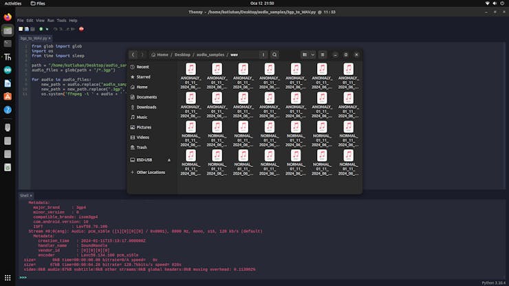
⭐ Obtain all 3GP audio samples in the audio_samples folder.
⭐ Convert each 3GP file to the WAV format and save them in the wav folder.
from glob import globimport osfrom time import sleeppath = "/home/kutluhan/Desktop/audio_samples"audio_files = glob(path + "/*.3gp")for audio in audio_files: new_path = audio.replace("audio_samples/", "audio_samples/wav/") new_path = new_path.replace(".3gp", ".wav") os.system('ffmpeg -i ' + audio + ' ' + new_path)![]()
![]()
![]()
-
17Step 10.2: Uploading formatted samples to Edge Impulse
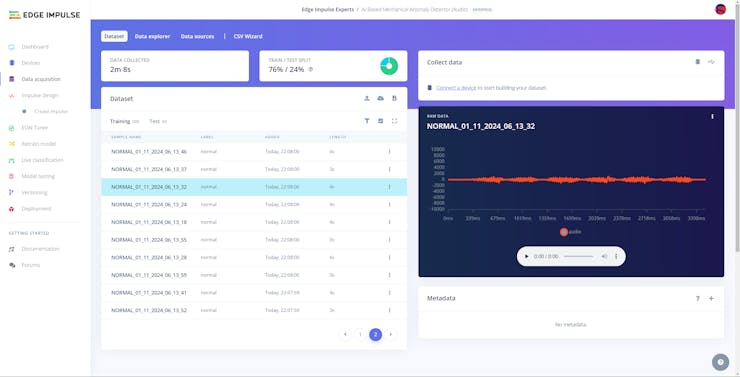
After collecting training and testing audio samples, I uploaded them to my project on Edge Impulse.
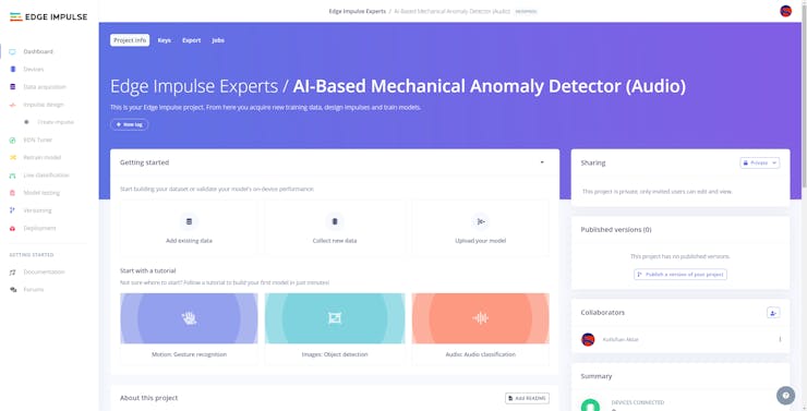
#️⃣ First of all, sign up for Edge Impulse and create a new project.
![]()
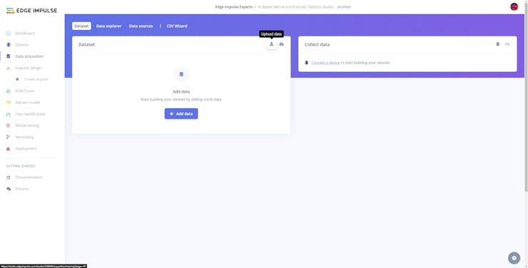
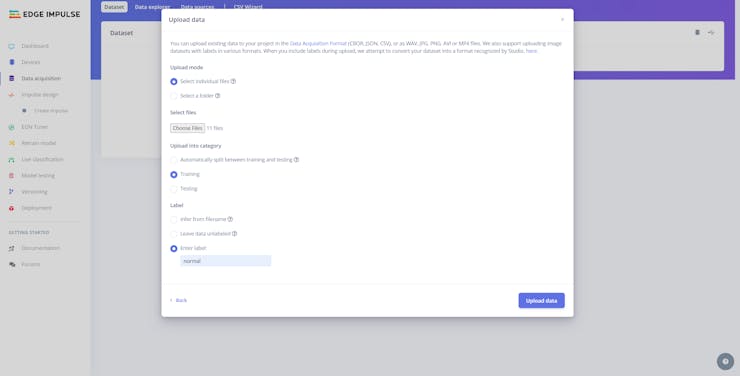
#️⃣ Navigate to the Data acquisition page and click the Upload data icon.
![]()
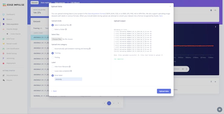
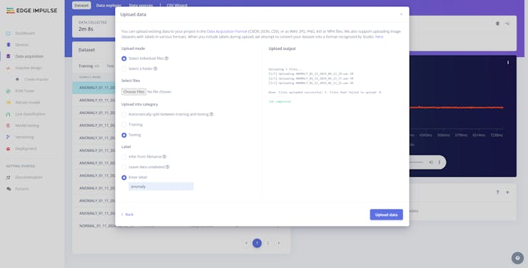
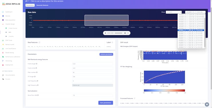
#️⃣ Choose the data category (training or testing) and select WAV audio files.
#️⃣ Utilize the Enter Label section to label audio samples manually with the operation status mentioned in the file names.
#️⃣ Then, click the Upload data button to upload the selected audio samples.
![]()
![]()
![]()
![]()
![]()
![]()
![]()
-
18Step 10.3: Training the model on sound-based anomalous behavior
After uploading and labeling my training and testing samples successfully, I designed an impulse and trained the model to detect sound-based mechanical anomalies.
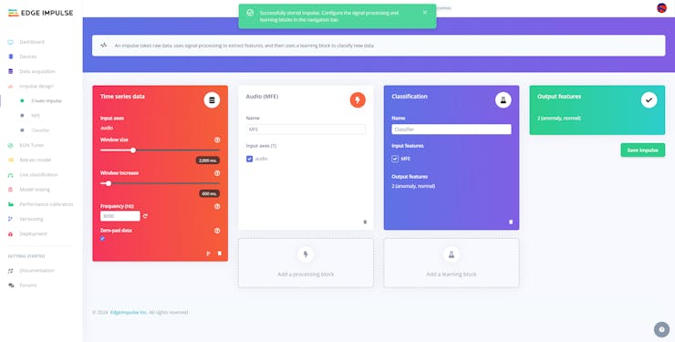
An impulse is a custom neural network model in Edge Impulse. I created my impulse by employing the Audio (MFE) processing block and the Classification learning block.
As mentioned earlier, Edge Impulse supports splitting raw audio samples into multiple windows by adjusting the parameters of the Time series data section.
- Window size — duration in milliseconds
- Window increase — offset (padding) of each subsequent window
The MFE (Mel Frequency Energy) signal processing block simplifies the generated raw audio windows, which contain a large amount of redundant information.
The Classification learning block represents a Keras neural network model. Also, it lets the user change the model settings, architecture, and layers.
#️⃣ Go to the Create impulse page and set Window size and Window increase parameters to 2000 and 600 respectively. In this regard, slice the given training and testing raw audio samples.
![]()
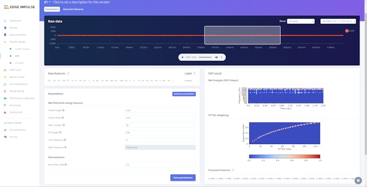
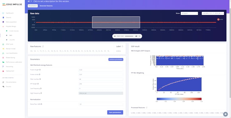
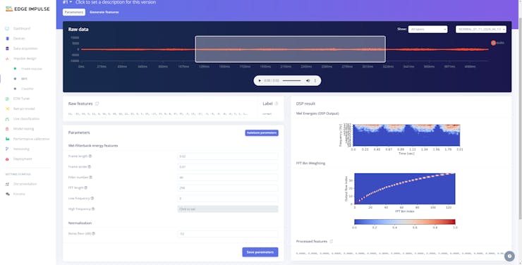
#️⃣ Before generating features for the neural network model, go to the MFE page to configure the MFE block if required.
#️⃣ Since the MFE block transforms a generated window into a table of data where each row represents a range of frequencies and each column represents a span of time, you can configure block parameters to adjust the frequency amplitude to change the MFE's output — spectrogram.
#️⃣ After inspecting each audio sample, I decided to utilize the default MFE parameters since my audio samples are simple enough not to require precise tuning.
#️⃣ Click Save parameters to save the given MFE parameters.
![]()
![]()
![]()
![]()
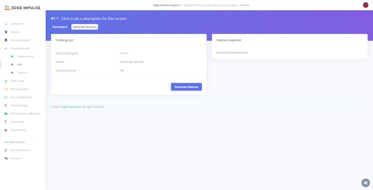
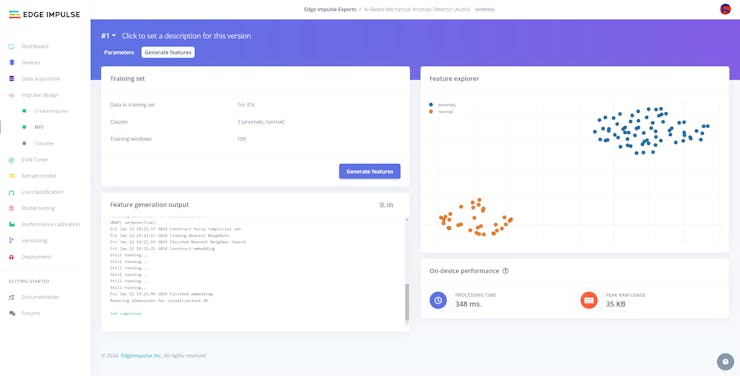
#️⃣ After saving parameters, click Generate features to apply the MFE signal processing block to training samples.
![]()
![]()
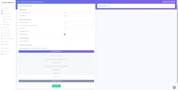
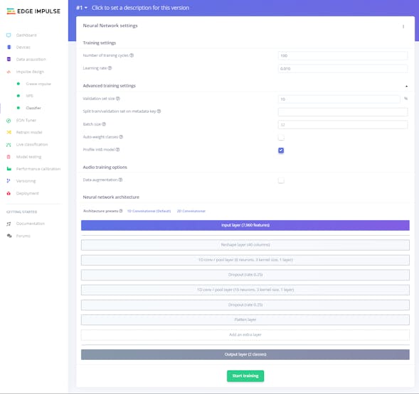
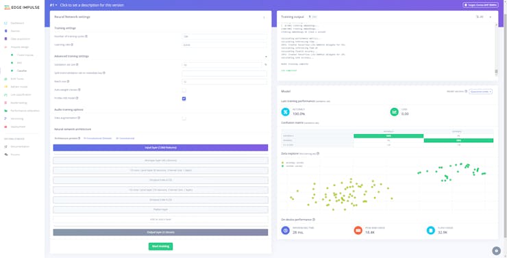
#️⃣ Finally, navigate to the Classifier page and click Start training.
![]()
![]()
According to my experiments with my neural network model, I modified the neural network settings and architecture to build a neural network model with high accuracy and validity:
📌 Neural network settings:
- Number of training cycles ➡ 100
- Learning rate ➡ 0.010
- Validation set size ➡ 10
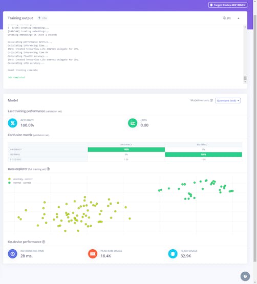
After generating features and training my model with training samples, Edge Impulse evaluated the precision score (accuracy) as 100>#/em###.
The precision score (accuracy) is approximately 100>#/em### due to the modest volume of training samples of sound-based mechanical anomalies, manifesting only timing belt malfunctions due to defective parts. Since the model can easily identify the inflicted anomaly, it performs excellently with a single-anomaly-type validation set. Therefore, I highly recommend retraining the model with specific mechanical deviation sounds before running inferences to detect complex system flaws in a production line.
![]()
![]()
-
19Step 10.4: Evaluating the model accuracy and deploying the model
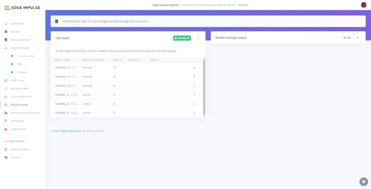
After building and training my neural network model, I tested its accuracy and validity by utilizing testing samples.
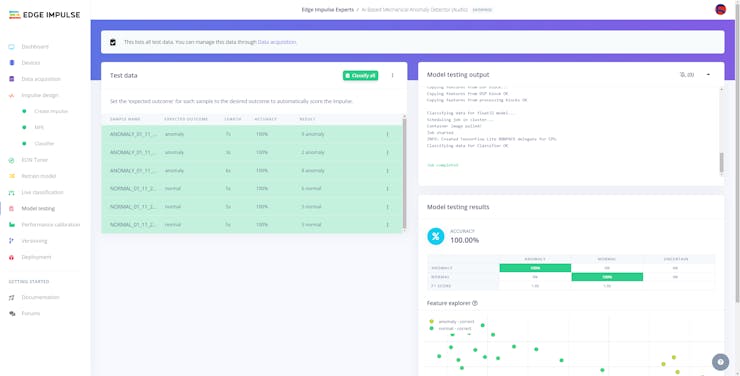
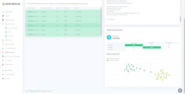
The evaluated accuracy of the model is 100>#/em###.
#️⃣ To validate the trained model, go to the Model testing page and click Classify all.
![]()
![]()
![]()
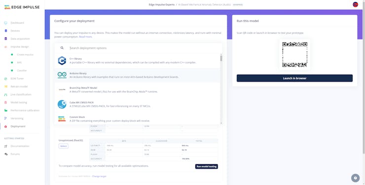
After validating my neural network model, I deployed it as a fully optimized and customizable Arduino library.
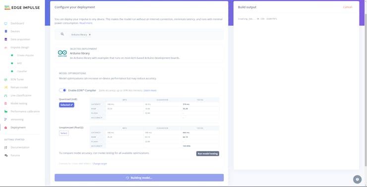
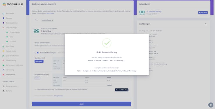
#️⃣ To deploy the validated model as an Arduino library, navigate to the Deployment page and search for Arduino library.
#️⃣ Then, choose the Quantized (int8) optimization option to get the best performance possible while running the deployed model.
#️⃣ Finally, click Build to download the model as an Arduino library.
![]()
![]()
![]()
-
20Step 11: Building an object detection (FOMO) model with Edge Impulse
When I completed capturing images of specialized components representing defective parts causing mechanical deviations in a production line and storing the captured samples on the microSD card, I started to work on my object detection (FOMO) model to diagnose the root cause of the detected mechanical anomaly as a result of audio classification.
Since Edge Impulse supports almost every microcontroller and development board due to its model deployment options, I decided to utilize Edge Impulse to build my object detection model. Also, Edge Impulse provides an elaborate machine learning algorithm (FOMO) for running more accessible and faster object detection models on edge devices such as FireBeetle 2 ESP32-S3.
Edge Impulse FOMO (Faster Objects, More Objects) is a novel machine learning algorithm that brings object detection to highly constrained devices. FOMO models can count objects, find the location of the detected objects in an image, and track multiple objects in real-time, requiring up to 30x less processing power and memory than MobileNet SSD or YOLOv5.
Even though Edge Impulse supports JPG or PNG files to upload as samples directly, each target object in a training or testing sample needs to be labeled manually. Therefore, I needed to follow the steps below to format my data set so as to train my object detection model accurately:
- Data Scaling (Resizing)
- Data Labeling
Since I added the component (part) classes and assigned sample numbers to the file names while capturing images of 3D-printed components (color-coded), I preprocessed my data set effortlessly to label each target object on an image sample on Edge Impulse by utilizing the color-coded component name:
- Red
- Green
- Blue
Plausibly, Edge Impulse allows building predictive models optimized in size and accuracy exceptionally and deploying the trained model as a supported firmware (Arduino library) for FireBeetle 2 ESP32-S3. Therefore, after scaling (resizing) and preprocessing my data set to label target objects, I was able to build an accurate object detection model to recognize specialized components (parts), which runs on FireBeetle 2 ESP32-S3 without any additional requirements.
You can inspect my object detection (FOMO) model on Edge Impulse as a public project.
Multi-Model AI-Based Mechanical Anomaly Detector
Apply sound data-based anomalous behavior detection, diagnose the root cause via object detection concurrently, and inform the user via SMS.


Discussions
Become a Hackaday.io Member
Create an account to leave a comment. Already have an account? Log In.