 kutluhan_aktar
-
21Step 11.1: Uploading images (samples) to Edge Impulse and labeling objects
After collecting training and testing image samples, I uploaded them to my project on Edge Impulse. Then, I labeled each target object on the image samples.
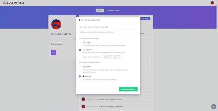
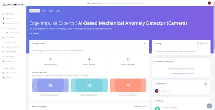
#️⃣ First of all, sign up for Edge Impulse and create a new project.
![]()
![]()
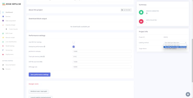
#️⃣ To be able to label image samples manually on Edge Impulse for object detection models, go to Dashboard ➡ Project info ➡ Labeling method and select Bounding boxes (object detection).
![]()
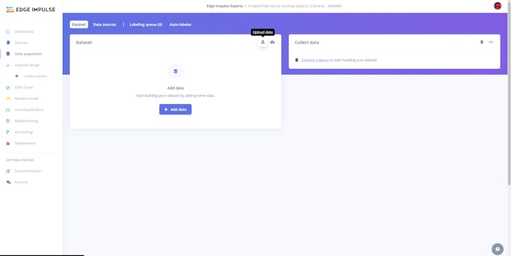
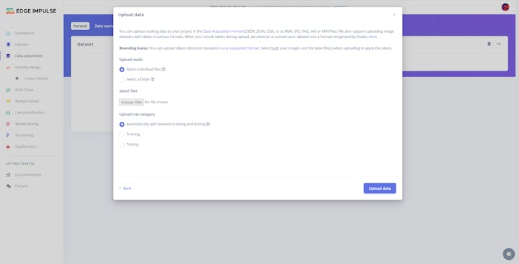
#️⃣ Navigate to the Data acquisition page and click the Upload data icon.
![]()
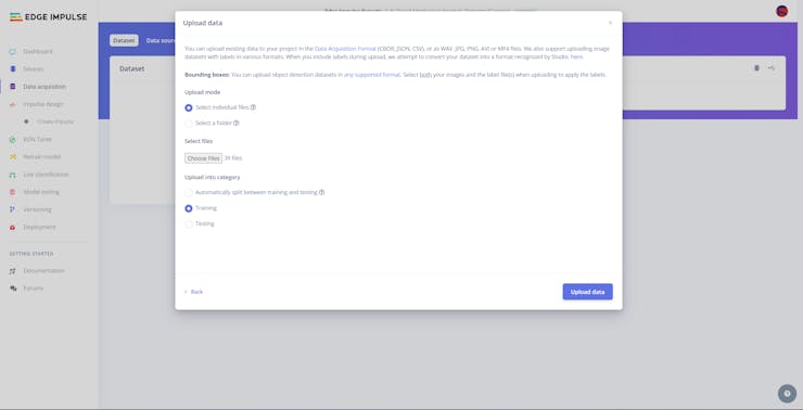
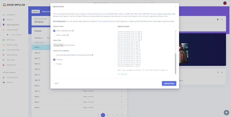
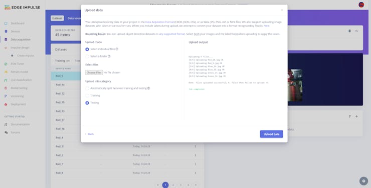
#️⃣ Then, choose the data category (training or testing), select image files, and click the Upload data button.
![]()
![]()
![]()
![]()
![]()
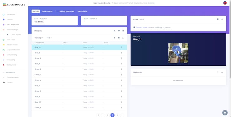
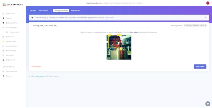
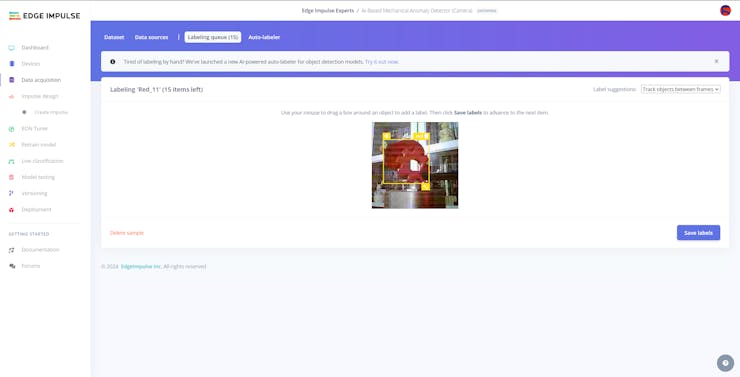
After uploading my data set successfully, I labeled each target object on the image samples by utilizing the color-coded component (part) class names. In Edge Impulse, labeling an object is as easy as dragging a box around it and entering a class. Also, Edge Impulse runs a tracking algorithm in the background while labeling objects, so it moves the bounding boxes automatically for the same target objects in different images.
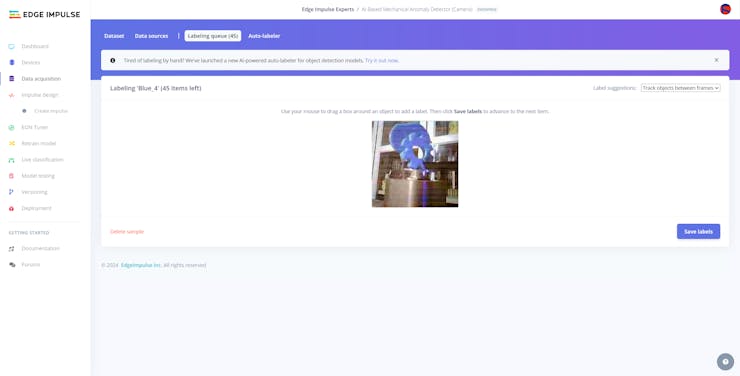
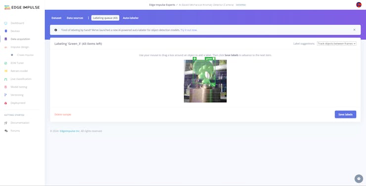
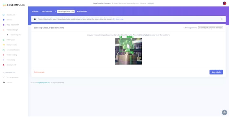
#️⃣ Go to Data acquisition ➡ Labeling queue. It shows all unlabeled items (training and testing) remaining in the given data set.
#️⃣ Finally, select an unlabeled item, drag bounding boxes around target objects, click the Save labels button, and repeat this process until all samples have at least one labeled target object.
![]()
![]()
![]()
![]()
![]()
![]()
![]()
![]()
![]()
-
22Step 11.2: Training the FOMO model on the faulty component images
After labeling target objects on my training and testing samples successfully, I designed an impulse and trained the model on detecting specialized components representing faulty parts causing mechanical anomalies in a production line.
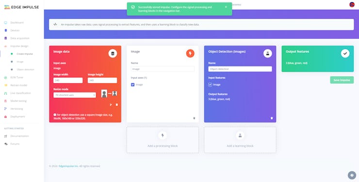
An impulse is a custom neural network model in Edge Impulse. I created my impulse by employing the Image preprocessing block and the Object Detection (Images) learning block.
The Image preprocessing block optionally turns the input image format to grayscale and generates a features array from the raw image.
The Object Detection (Images) learning block represents a machine learning algorithm that detects objects on the given image, distinguished between model labels.
In this case, I configured the input image format as RGB since the 3D-printed components (parts) are identical except for their colors.
#️⃣ Go to the Create impulse page and set image width and height parameters to 240. Then, select the resize mode parameter as Fit shortest axis so as to scale (resize) given training and testing image samples.
#️⃣ Select the Image preprocessing block and the Object Detection (Images) learning block. Finally, click Save Impulse.
![]()
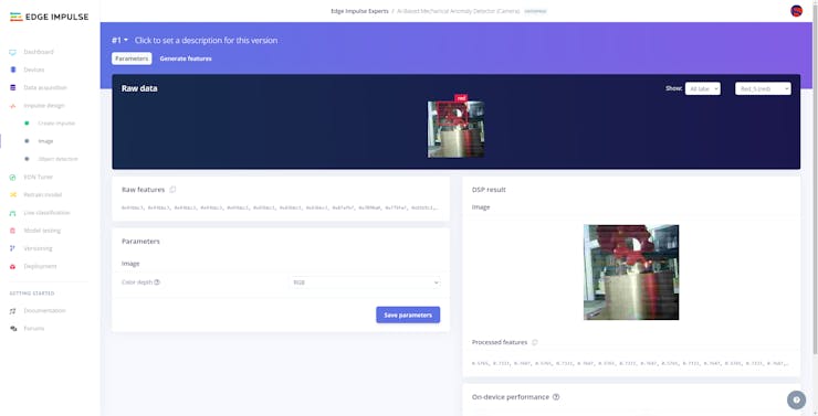
#️⃣ Before generating features for the object detection model, go to the Image page and set the Color depth parameter as RGB. Then, click Save parameters.
![]()
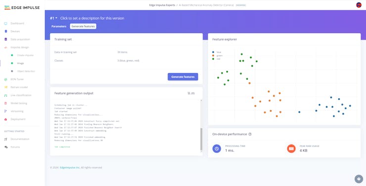
#️⃣ After saving parameters, click Generate features to apply the Image preprocessing block to training image samples.
![]()
![]()
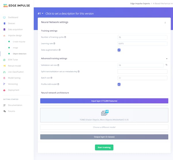
#️⃣ After generating features successfully, navigate to the Object detection page and click Start training.
![]()
![]()
According to my experiments with my object detection model, I modified the neural network settings and architecture to build an object detection model with high accuracy and validity:
📌 Neural network settings:
- Number of training cycles ➡ 70
- Learning rate ➡ 0.015
- Validation set size ➡ 10
📌 Neural network architecture:
- FOMO (Faster Objects, More Objects) MobileNetV2 0.35
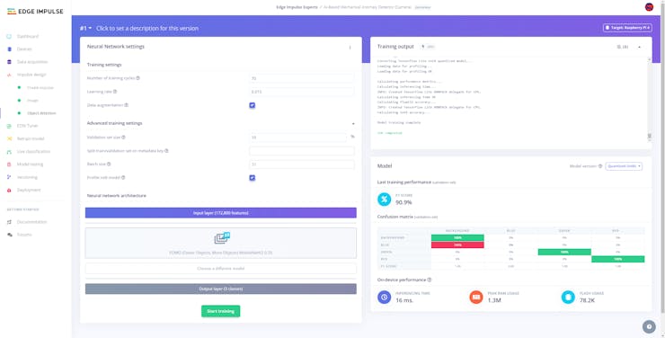
After generating features and training my FOMO model with training samples, Edge Impulse evaluated the F1 score (accuracy) as 90.9>#/em###.
The F1 score (accuracy) is approximately 90.9>#/em### due to the modest volume of training samples of diverse defective parts with distinct shapes and colors. Since the model can precisely recognize the 3D-printed components (parts) that are identical but their colors, it performs excellently with a small validation set. Therefore, I highly recommend retraining the model with the specific faulty parts for the targeted production line before running inferences.
![]()
-
23Step 11.3: Evaluating the model accuracy and deploying the model
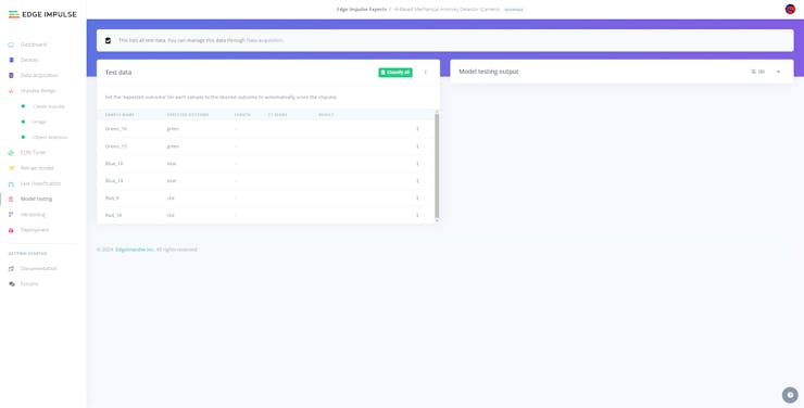
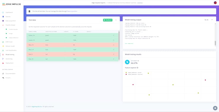
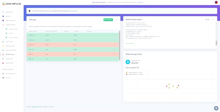
After building and training my object detection model, I tested its accuracy and validity by utilizing testing image samples.
The evaluated accuracy of the model is 66.67>#/em###.
#️⃣ To validate the trained model, go to the Model testing page and click Classify all.
![]()
![]()
![]()
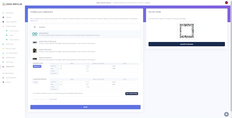
After validating my object detection model, I deployed it as a fully optimized and customizable Arduino library.
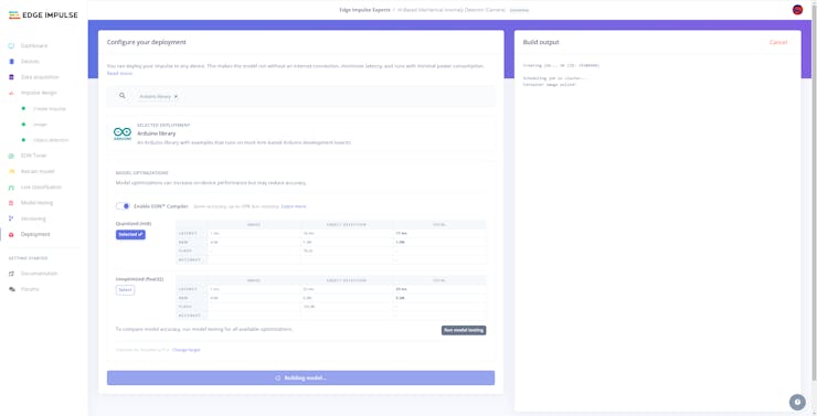
#️⃣ To deploy the validated model as an Arduino library, navigate to the Deployment page and search for Arduino library.
#️⃣ Then, choose the Quantized (int8) optimization option to get the best performance possible while running the deployed model.
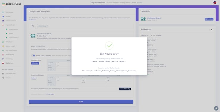
#️⃣ Finally, click Build to download the model as an Arduino library.
![]()
![]()
![]()
-
24Step 12: Setting up the neural network model on Beetle ESP32-C3
After building, training, and deploying my neural network model as an Arduino library on Edge Impulse, I needed to upload the generated Arduino library on Beetle ESP32-C3 to run the model directly so as to detect sound-based mechanical anomalies with minimal latency, memory usage, and power consumption.
Since Edge Impulse optimizes and formats signal processing, configuration, and learning blocks into a single package while deploying models as Arduino libraries, I was able to import my model effortlessly to run inferences.
#️⃣ After downloading the model as an Arduino library in the ZIP file format, go to Sketch ➡ Include Library ➡ Add.ZIP Library...
#️⃣ Then, include the AI-Based_Mechanical_Anomaly_Detector_Audio__inferencing.h file to import the Edge Impulse neural network model.
#include <AI-Based_Mechanical_Anomaly_Detector_Audio__inferencing.h>
After importing my model successfully to the Arduino IDE, I programmed Beetle ESP32-C3 to run inferences to detect sound-based mechanical anomalies.
Then, I employed Beetle ESP32-C3 to transfer the model detection results to the Android application via BLE after running an inference successfully.
As explained earlier, Beetle ESP32-C3 can communicate with the Android application over BLE to receive commands and transfer data packets to FireBeetle 2 ESP32-S3 via serial communication.
Since interconnected features for data collection and running neural network models are parts of two separate code files, you can check the overlapping functions and instructions in Step 9. Please refer to the code files to inspect all interconnected functions in detail.
📁 AIoT_Mechanical_Anomaly_Detector_Audio.ino
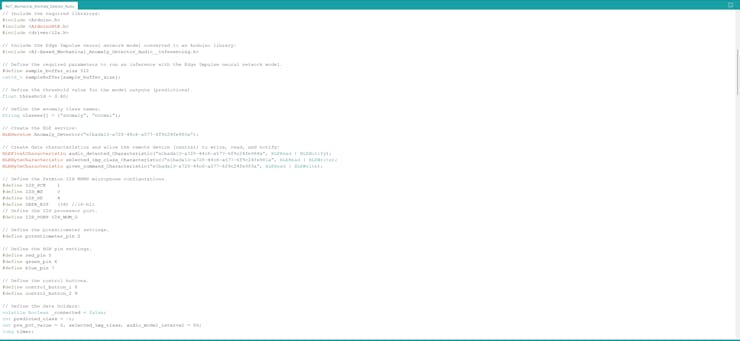
⭐ Define the required parameters to run an inference with the Edge Impulse neural network model for audio classification.
#define sample_buffer_size 512int16_t sampleBuffer[sample_buffer_size];
⭐ Define the threshold value (0.60) for the model outputs (predictions).
⭐ Define the operation status class names.
float threshold = 0.60;// Define the anomaly class names:String classes[] = {"anomaly", "normal"};⭐ Define the Fermion I2S MEMS microphone pin configurations.
#define I2S_SCK 1#define I2S_WS 0#define I2S_SD 4#define DATA_BIT (16) //16-bit// Define the I2S processor port.#define I2S_PORT I2S_NUM_0
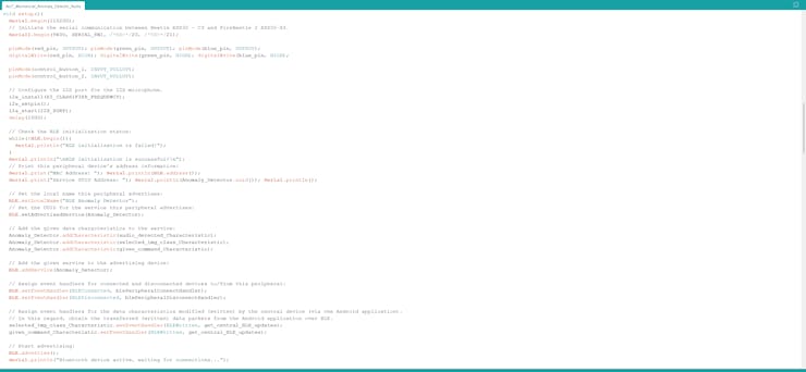
⭐ Set up the selected I2S port for the I2S microphone.
i2s_install(EI_CLASSIFIER_FREQUENCY); i2s_setpin(); i2s_start(I2S_PORT); delay(1000);
⭐ In the i2s_install function, configure the I2S processor port for the I2S microphone in the ONLY_LEFT mode.
void i2s_install(uint32_t sampling_rate){ // Configure the I2S processor port for the I2S microphone (ONLY_LEFT). const i2s_config_t i2s_config = { .mode = i2s_mode_t(I2S_MODE_MASTER | I2S_MODE_RX), .sample_rate = sampling_rate, .bits_per_sample = i2s_bits_per_sample_t(DATA_BIT), .channel_format = I2S_CHANNEL_FMT_ONLY_LEFT, .communication_format = i2s_comm_format_t(I2S_COMM_FORMAT_STAND_I2S), .intr_alloc_flags = 0, .dma_buf_count = 8, .dma_buf_len = sample_buffer_size, .use_apll = false }; i2s_driver_install(I2S_PORT, &i2s_config, 0, NULL);}⭐ In the i2s_setpin function, assign the provided I2S microphone pin configuration to the given I2S port.
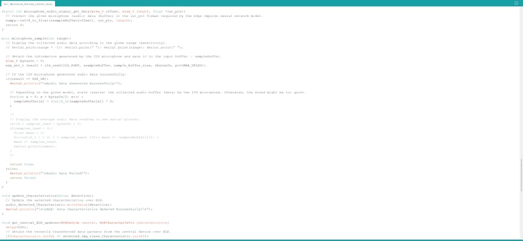
void i2s_setpin(){ // Set the I2S microphone pin configuration. const i2s_pin_config_t pin_config = { .bck_io_num = I2S_SCK, .ws_io_num = I2S_WS, .data_out_num = -1, .data_in_num = I2S_SD }; i2s_set_pin(I2S_PORT, &pin_config);}⭐ In the microphone_sample function:
⭐ Obtain the data generated by the I2S microphone and save it to the input buffer — sampleBuffer.
⭐ If the I2S microphone works accurately, scale (resize) the collected audio buffer (data) depending on the given model. Otherwise, the sound might be too quiet for audio classification.
bool microphone_sample(int range){ // Display the collected audio data according to the given range (sensitivity). // Serial.print(range * -1); Serial.print(" "); Serial.print(range); Serial.print(" "); // Obtain the information generated by the I2S microphone and save it to the input buffer — sampleBuffer. size_t bytesIn = 0; esp_err_t result = i2s_read(I2S_PORT, &sampleBuffer, sample_buffer_size, &bytesIn, portMAX_DELAY); // If the I2S microphone generates audio data successfully: if(result == ESP_OK){ Serial.println("\nAudio Data Generated Successfully!"); // Depending on the given model, scale (resize) the collected audio buffer (data) by the I2S microphone. Otherwise, the sound might be too quiet. for(int x = 0; x < bytesIn/2; x++) { sampleBuffer[x] = (int16_t)(sampleBuffer[x]) * 8; } /* // Display the average audio data reading on the serial plotter. int16_t samples_read = bytesIn / 8; if(samples_read > 0){ float mean = 0; for(int16_t i = 0; i < samples_read; ++i){ mean += (sampleBuffer[i]); } mean /= samples_read; Serial.println(mean); } */ return true; }else{ Serial.println("\nAudio Data Failed!"); return false; }}⭐ In the run_inference_to_make_predictions function:
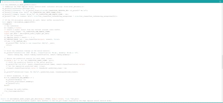
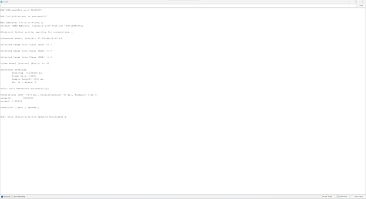
⭐ Summarize the Edge Impulse neural network model inference settings and print them on the serial monitor.
⭐ If the I2S microphone generates an audio (data) buffer successfully:
⭐ Create a signal object from the resized (scaled) audio buffer.
⭐ Run an inference.
⭐ Print the inference timings on the serial monitor.
⭐ Obtain the prediction results for each label (class).
⭐ Print the model detection results on the serial monitor.
⭐ Get the imperative predicted label (class).
⭐ Print inference anomalies on the serial monitor, if any.
void run_inference_to_make_predictions(){ // Summarize the Edge Impulse neural network model inference settings (from model_metadata.h): ei_printf("\nInference settings:\n"); ei_printf("\tInterval: "); ei_printf_float((float)EI_CLASSIFIER_INTERVAL_MS); ei_printf(" ms.\n"); ei_printf("\tFrame size: %d\n", EI_CLASSIFIER_DSP_INPUT_FRAME_SIZE); ei_printf("\tSample length: %d ms.\n", EI_CLASSIFIER_RAW_SAMPLE_COUNT / 16); ei_printf("\tNo. of classes: %d\n", sizeof(ei_classifier_inferencing_categories) / sizeof(ei_classifier_inferencing_categories[0])); // If the I2S microphone generates an audio (data) buffer successfully: bool sample = microphone_sample(2000); if(sample){ // Run inference: ei::signal_t signal; // Create a signal object from the resized (scaled) audio buffer. signal.total_length = EI_CLASSIFIER_RAW_SAMPLE_COUNT; signal.get_data = µphone_audio_signal_get_data; // Run the classifier: ei_impulse_result_t result = { 0 }; EI_IMPULSE_ERROR _err = run_classifier(&signal, &result, false); if(_err != EI_IMPULSE_OK){ ei_printf("ERR: Failed to run classifier (%d)\n", _err); return; } // Print the inference timings on the serial monitor. ei_printf("\nPredictions (DSP: %d ms., Classification: %d ms., Anomaly: %d ms.): \n", result.timing.dsp, result.timing.classification, result.timing.anomaly); // Obtain the prediction results for each label (class). for(size_t ix = 0; ix < EI_CLASSIFIER_LABEL_COUNT; ix++){ // Print the prediction results on the serial monitor. ei_printf("%s:\t%.5f\n", result.classification[ix].label, result.classification[ix].value); // Get the imperative predicted label (class). if(result.classification[ix].value >= threshold) predicted_class = ix; } ei_printf("\nPredicted Class: %d [%s]\n", predicted_class, classes[predicted_class]); // Detect anomalies, if any: #if EI_CLASSIFIER_HAS_ANOMALY == 1 ei_printf("Anomaly: "); ei_printf_float(result.anomaly); ei_printf("\n"); #endif // Release the audio buffer. //ei_free(sampleBuffer); }}⭐ In the microphone_audio_signal_get_data function, convert the passed audio data buffer from the I2S microphone to the out_ptr format required by the Edge Impulse neural network model.
static int microphone_audio_signal_get_data(size_t offset, size_t length, float *out_ptr){ // Convert the given microphone (audio) data (buffer) to the out_ptr format required by the Edge Impulse neural network model. numpy::int16_to_float(&sampleBuffer[offset], out_ptr, length); return 0;}⭐ In the update_characteristics function, update the float data characteristic to transmit (advertise) the detected sound-based mechanical anomaly.
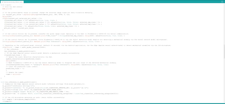
void update_characteristics(float detection){ // Update the selected characteristics over BLE. audio_detected_Characteristic.writeValue(detection); Serial.println("\n\nBLE: Data Characteristics Updated Successfully!\n");}⭐ Every 80 seconds, the default model interval which can be configured from 30 to 120 via the Android application, run an inference with the Edge Impulse neural network model.
⭐ If the model detects a sound-based mechanical anomaly successfully:
⭐ Transfer the model detection results to the Android application over BLE.
⭐ Via serial communication, make FireBeetle 2 ESP32-S3 run the object detection model to diagnose the root cause of the detected mechanical anomaly.
⭐ Clear the predicted class (label).
⭐ Finally, update the timer.
if(millis() - timer > audio_model_interval*1000){ // Run inference. run_inference_to_make_predictions(); // If the Edge Impulse neural network model detects a mechanical anomaly successfully: if(predicted_class > -1){ // Update the audio detection characteristic via BLE. update_characteristics(predicted_class); delay(2000); // Make FireBeetle 2 ESP32-S3 to run the object detection model to diagnose the root cause of the detected mechanical anomaly. if(classes[predicted_class] == "anomaly") Serial1.print("Run Inference"); delay(500); adjustColor(true, false, true); // Clear the predicted class (label). predicted_class = -1; } // Update the timer: timer = millis(); }![]()
![]()
![]()
![]()
![]()
-
25Step 13: Setting up the object detection model on FireBeetle 2 ESP32-S3
After building, training, and deploying my object detection model as an Arduino library on Edge Impulse, I needed to upload the generated Arduino library to FireBeetle 2 ESP32-S3 to run the model directly so as to recognize the specialized components (parts) with minimal latency, memory usage, and power consumption.
Since Edge Impulse optimizes and formats signal processing, configuration, and learning blocks into a single package while deploying models as Arduino libraries, I was able to import my model effortlessly to run inferences.
#️⃣ After downloading the model as an Arduino library in the ZIP file format, go to Sketch ➡ Include Library ➡ Add.ZIP Library...
#️⃣ Then, include the AI-Based_Mechanical_Anomaly_Detector_Camera__inferencing.h file to import the Edge Impulse object detection model.
#include <AI-Based_Mechanical_Anomaly_Detector_Camera__inferencing.h>
After importing my model successfully to the Arduino IDE, I programmed FireBeetle 2 ESP32-S3 to run inferences to diagnose the root cause of the inflicted mechanical anomaly.
As explained earlier, FireBeetle 2 ESP32-S3 runs an inference with the object detection model automatically if Beetle ESP32-C3 detects a sound-based mechanical anomaly. Nevertheless, the user can force FireBeetle 2 ESP32-S3 to run the object detection model manually or via the Android application for debugging.
Since interconnected features for data collection and running neural network models are parts of two separate code files, you can check the overlapping functions and instructions in Step 9. Please refer to the code files to inspect all interconnected functions in detail.
📁 AIoT_Mechanical_Anomaly_Detector_Camera.ino
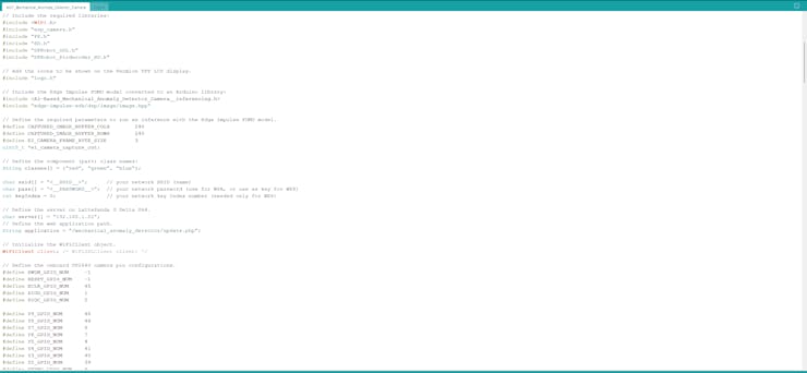
⭐ Include the built-in Edge Impulse image functions.
⭐ Define the required parameters to run an inference with the Edge Impulse FOMO model.
#include "edge-impulse-sdk/dsp/image/image.hpp"// Define the required parameters to run an inference with the Edge Impulse FOMO model.#define CAPTURED_IMAGE_BUFFER_COLS 240#define CAPTURED_IMAGE_BUFFER_ROWS 240#define EI_CAMERA_FRAME_BYTE_SIZE 3uint8_t *ei_camera_capture_out;
⭐ Define the color-coded component (part) class names.
String classes[] = {"red", "green", "blue"};⭐ Define the Wi-Fi network and the web application settings hosted by LattePanda 3 Delta 864.
⭐ Initialize the WiFiClient object.
char ssid[] = "<__SSID__>"; // your network SSID (name)char pass[] = "<__PASSWORD__>"; // your network password (use for WPA, or use as key for WEP)int keyIndex = 0; // your network key Index number (needed only for WEP)// Define the server on LattePanda 3 Delta 864.char server[] = "192.168.1.22";// Define the web application path.String application = "/mechanical_anomaly_detector/update.php";// Initialize the WiFiClient object.WiFiClient client; /* WiFiSSLClient client; */
⭐ Create a struct (_data) including all resulting bounding box parameters.
struct _data { String x; String y; String w; String h;};struct _data box;⭐ Initialize the Wi-Fi module and attempt to connect to the given Wi-Fi network.
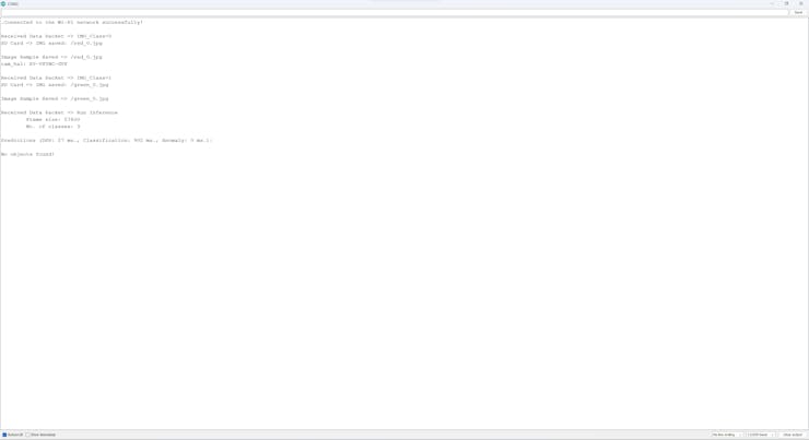
WiFi.mode(WIFI_STA); WiFi.begin(ssid, pass); // Attempt to connect to the given Wi-Fi network. while(WiFi.status() != WL_CONNECTED){ // Wait for the network connection. delay(500); Serial.print("."); } // If connected to the network successfully: Serial.println("Connected to the Wi-Fi network successfully!");⭐ In the run_inference_to_make_predictions function:
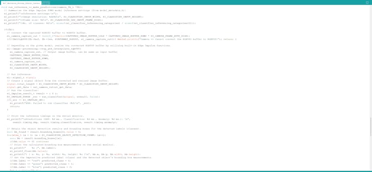
⭐ Summarize the Edge Impulse FOMO model inference settings and print them on the serial monitor.
⭐ Convert the passed RGB565 raw image buffer to an RGB888 image buffer by utilizing the built-in fmt2rgb888 function.
⭐ Depending on the given model, resize the converted RGB888 buffer by utilizing built-in Edge Impulse image functions.
⭐ Create a signal object from the converted and resized image buffer.
⭐ Run an inference.
⭐ Print the inference timings on the serial monitor.
⭐ Obtain labels (classes) and bounding box measurements for each detected target object on the given image buffer.
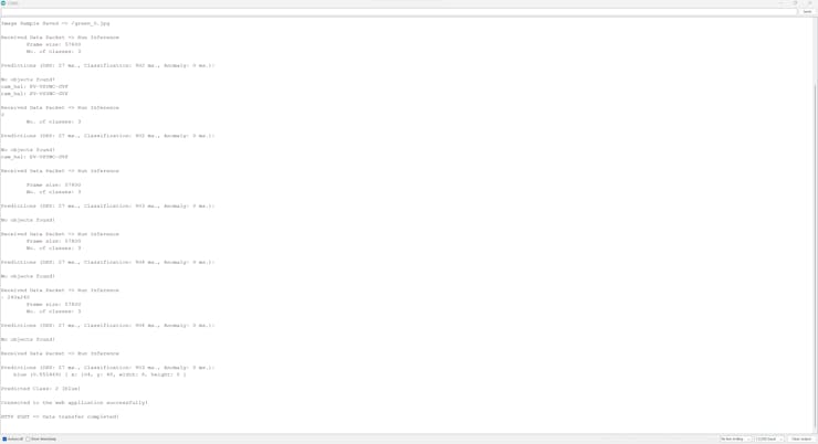
⭐ Print the model detection results and the calculated bounding box measurements on the serial monitor.
⭐ Get the imperative predicted label (class) and save its bounding box measurements as the box struct parameters.
⭐ Print inference anomalies on the serial monitor, if any.
⭐ Release the image buffer.
void run_inference_to_make_predictions(camera_fb_t *fb){ // Summarize the Edge Impulse FOMO model inference settings (from model_metadata.h): ei_printf("\nInference settings:\n"); ei_printf("\tImage resolution: %dx%d\n", EI_CLASSIFIER_INPUT_WIDTH, EI_CLASSIFIER_INPUT_HEIGHT); ei_printf("\tFrame size: %d\n", EI_CLASSIFIER_DSP_INPUT_FRAME_SIZE); ei_printf("\tNo. of classes: %d\n", sizeof(ei_classifier_inferencing_categories) / sizeof(ei_classifier_inferencing_categories[0])); if(fb){ // Convert the captured RGB565 buffer to RGB888 buffer. ei_camera_capture_out = (uint8_t*)malloc(CAPTURED_IMAGE_BUFFER_COLS * CAPTURED_IMAGE_BUFFER_ROWS * EI_CAMERA_FRAME_BYTE_SIZE); if(!fmt2rgb888(fb->buf, fb->len, PIXFORMAT_RGB565, ei_camera_capture_out)){ Serial.println("Camera => Cannot convert the RGB565 buffer to RGB888!"); return; } // Depending on the given model, resize the converted RGB888 buffer by utilizing built-in Edge Impulse functions. ei::image::processing::crop_and_interpolate_rgb888( ei_camera_capture_out, // Output image buffer, can be same as input buffer CAPTURED_IMAGE_BUFFER_COLS, CAPTURED_IMAGE_BUFFER_ROWS, ei_camera_capture_out, EI_CLASSIFIER_INPUT_WIDTH, EI_CLASSIFIER_INPUT_HEIGHT); // Run inference: ei::signal_t signal; // Create a signal object from the converted and resized image buffer. signal.total_length = EI_CLASSIFIER_INPUT_WIDTH * EI_CLASSIFIER_INPUT_HEIGHT; signal.get_data = &ei_camera_cutout_get_data; // Run the classifier: ei_impulse_result_t result = { 0 }; EI_IMPULSE_ERROR _err = run_classifier(&signal, &result, false); if(_err != EI_IMPULSE_OK){ ei_printf("ERR: Failed to run classifier (%d)\n", _err); return; } // Print the inference timings on the serial monitor. ei_printf("\nPredictions (DSP: %d ms., Classification: %d ms., Anomaly: %d ms.): \n", result.timing.dsp, result.timing.classification, result.timing.anomaly); // Obtain the object detection results and bounding boxes for the detected labels (classes). bool bb_found = result.bounding_boxes[0].value > 0; for(size_t ix = 0; ix < EI_CLASSIFIER_OBJECT_DETECTION_COUNT; ix++){ auto bb = result.bounding_boxes[ix]; if(bb.value == 0) continue; // Print the calculated bounding box measurements on the serial monitor. ei_printf(" %s (", bb.label); ei_printf_float(bb.value); ei_printf(") [ x: %u, y: %u, width: %u, height: %u ]\n", bb.x, bb.y, bb.width, bb.height); // Get the imperative predicted label (class) and the detected object's bounding box measurements. if(bb.label == "red") predicted_class = 0; if(bb.label == "green") predicted_class = 1; if(bb.label == "blue") predicted_class = 2; box.x = String(bb.x); box.y = String(bb.y); box.w = String(bb.width); box.h = String(bb.height); ei_printf("\nPredicted Class: %d [%s]\n", predicted_class, classes[predicted_class]); } if(!bb_found) ei_printf("\nNo objects found!\n"); // Detect anomalies, if any: #if EI_CLASSIFIER_HAS_ANOMALY == 1 ei_printf("Anomaly: "); ei_printf_float(result.anomaly); ei_printf("\n"); #endif // Release the image buffer. free(ei_camera_capture_out); }}⭐ In the ei_camera_cutout_get_data function,
⭐ Convert the passed image data (buffer) to the out_ptr format required by the Edge Impulse FOMO model.
⭐ Since the given image data is already converted to an RGB888 buffer and resized, directly recalculate the given offset into pixel index.
static int ei_camera_cutout_get_data(size_t offset, size_t length, float *out_ptr){ // Convert the given image data (buffer) to the out_ptr format required by the Edge Impulse FOMO model. size_t pixel_ix = offset * 3; size_t pixels_left = length; size_t out_ptr_ix = 0; // Since the image data is converted to an RGB888 buffer, directly recalculate offset into pixel index. while(pixels_left != 0){ out_ptr[out_ptr_ix] = (ei_camera_capture_out[pixel_ix] << 16) + (ei_camera_capture_out[pixel_ix + 1] << 8) + ei_camera_capture_out[pixel_ix + 2]; // Move to the next pixel. out_ptr_ix++; pixel_ix+=3; pixels_left--; } return 0;}⭐ In the make_a_post_request function:
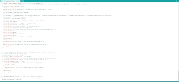
⭐ Connect to the web application named mechanical_anomaly_detector.
⭐ Create the query string by adding the given URL query (GET) parameters, including model detection results and the bounding box measurements.
⭐ Define the boundary parameter named AnomalyResult so as to send the captured raw image buffer (RGB565) as a TXT file to the web application.
⭐ Get the total content length.
⭐ Make an HTTP POST request with the created query string to the web application in order to transfer the captured raw image buffer as a TXT file and the model detection results.
⭐ Wait until transferring the image buffer.
void make_a_post_request(camera_fb_t * fb, String request){ // Connect to the web application named mechanical_anomaly_detector. Change '80' with '443' if you are using SSL connection. if (client.connect(server, 80)){ // If successful: Serial.println("\nConnected to the web application successfully!\n"); // Create the query string: String query = application + request; // Make an HTTP POST request: String head = "--AnomalyResult\r\nContent-Disposition: form-data; name=\"resulting_image\"; filename=\"new_image.txt\"\r\nContent-Type: text/plain\r\n\r\n"; String tail = "\r\n--AnomalyResult--\r\n"; // Get the total message length. uint32_t totalLen = head.length() + fb->len + tail.length(); // Start the request: client.println("POST " + query + " HTTP/1.1"); client.println("Host: 192.168.1.22"); client.println("Content-Length: " + String(totalLen)); client.println("Connection: Keep-Alive"); client.println("Content-Type: multipart/form-data; boundary=AnomalyResult"); client.println(); client.print(head); client.write(fb->buf, fb->len); client.print(tail); // Wait until transferring the image buffer. delay(2000); // If successful: Serial.println("HTTP POST => Data transfer completed!\n"); }else{ Serial.println("\nConnection failed to the web application!\n"); delay(2000); }}⭐ If Beetle ESP32-C3 transfers the Run Inference command via serial communication:
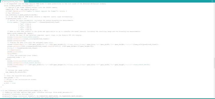
⭐ Capture a new frame (RGB565 buffer) with the onboard OV2640 camera.
⭐ Run an inference with the Edge Impulse FOMO model to make predictions on the specialized component (part) classes.
⭐ If the Edge Impulse FOMO model detects a component (part) class successfully:
⭐ Define the query (GET) parameters, including the calculated bounding box measurements.
⭐ Send the model detection results, the bounding box measurements, and the resulting image (RGB565 buffer) to the given web application via an HTTP POST request.
⭐ Then, notify the user by showing the Gear icon with the assigned class color on the Fermion TFT display.
⭐ Clear the predicted class (label).
⭐ Release the image buffer.
⭐ Finally, clear the data packet received via serial communication and return to the initialization screen.
... }else if(data_packet.indexOf("Run") > -1){ // Capture a new frame (RGB565 buffer) with the OV2640 camera. camera_fb_t *fb = esp_camera_fb_get(); if(!fb){ Serial.println("Camera => Cannot capture the frame!"); return; } // Run inference. run_inference_to_make_predictions(fb); // If the Edge Impulse FOMO model detects a component (part) class successfully: if(predicted_class > -1){ // Define the query parameters, including the passed bounding box measurements. String query = "?results=OK&class=" + classes[predicted_class] + "&x=" + box.x + "&y=" + box.y + "&w=" + box.w + "&h=" + box.h; // Make an HTTP POST request to the given web application so as to transfer the model results, including the resulting image and the bounding box measurements. make_a_post_request(fb, query); // Notify the user of the detected component (part) class on the Fermion TFT LCD display. screen.fillScreen(COLOR_RGB565_BLACK); screen.setTextColor(class_color[predicted_class]); screen.setTextSize(4); // Display the gear icon with the assigned class color. screen.drawXBitmap(/*x=*/(240-gear_width)/2,/*y=*/(320-gear_height)/2,/*bitmap gImage_Bitmap=*/gear_bits,/*w=*/gear_width,/*h=*/gear_height,/*color=*/class_color[predicted_class]); screen.setCursor((240-(classes[predicted_class].length()*20))/2, ((320-gear_height)/2)+gear_height+30); String t = classes[predicted_class]; t.toUpperCase(); screen.println(t); delay(3000); // Clear the predicted class (label). predicted_class = -1; }else{ screen.fillScreen(COLOR_RGB565_BLACK); screen.setTextColor(COLOR_RGB565_WHITE); screen.drawXBitmap(/*x=*/(240-gear_width)/2,/*y=*/(320-gear_height)/2,/*bitmap gImage_Bitmap=*/gear_bits,/*w=*/gear_width,/*h=*/gear_height,/*color=*/COLOR_RGB565_WHITE); delay(3000); } // Release the image buffer. esp_camera_fb_return(fb); } // Clear the received data packet. data_packet = ""; // Return to the initialization screen. delay(500); s_init = true; }![]()
![]()
![]()
![]()
-
26Step 14: Running neural network and object detection models simultaneously to inform the user of the root cause of the detected anomaly via SMS
My Edge Impulse neural network model predicts possibilities of labels (operation status classes) for the given audio (features) buffer as an array of 2 numbers. They represent the model's "confidence" that the given features buffer corresponds to each of the two different status classes [0 - 1], as shown in Step 10:
- 0 — anomaly
- 1 — normal
My Edge Impulse object detection (FOMO) model scans a captured image buffer and predicts possibilities of trained labels to recognize a target object on the given picture. The prediction result (score) represents the model's "confidence" that the detected object corresponds to each of the three different color-coded component (part) classes [0 - 2], as shown in Step 11:
- 0 — blue
- 1 — green
- 2 — red
You can inspect overlapping Android application features, such as BLE peripheral scanning in the previous steps.
After setting up and running both models on Beetle ESP32-C3 and FireBeetle 2 ESP32-S3:
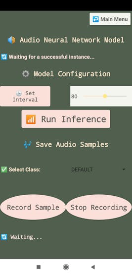
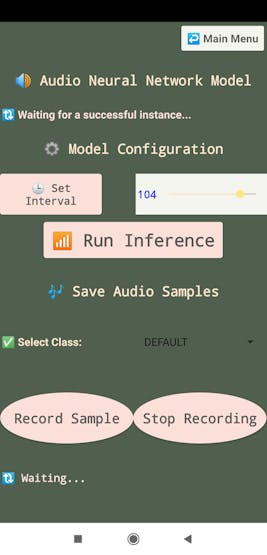
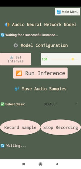
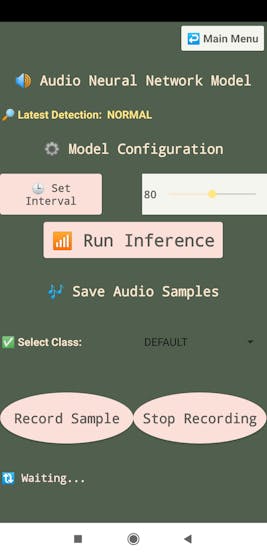
⚙️⚠️🔊📲 The Android application allows the user to configure the model interval value for running the neural network model for audio classification.
⚙️⚠️🔊📲 To change the model interval over BLE, go to the microphone configuration section and adjust the slider from 30 to 120 seconds.
⚙️⚠️🔊📲 Then, click the Set Interval button to update the default model interval — 80 seconds.
![]()
![]()
![]()
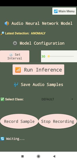
⚙️⚠️🔊📲 If the neural network model detects a sound-based mechanical anomaly successfully, Beetle ESP32-C3 transmits the model detection results to the Android application over BLE.
![]()
![]()
⚙️⚠️🔊📲 Then, Beetle ESP32-C3, via serial communication, makes FireBeetle 2 ESP32-S3 run the object detection model to diagnose the root cause of the detected sound-based mechanical anomaly.
![]()
![]()
⚙️⚠️🔊📲 In addition to consecutive model running, the user can force FireBeetle 2 ESP32-S3 to run the object detection model:
- by manually pressing the control button (B),
- or via the Android application by clicking the Run Inference button on the microphone configuration section.
![]()
![]()
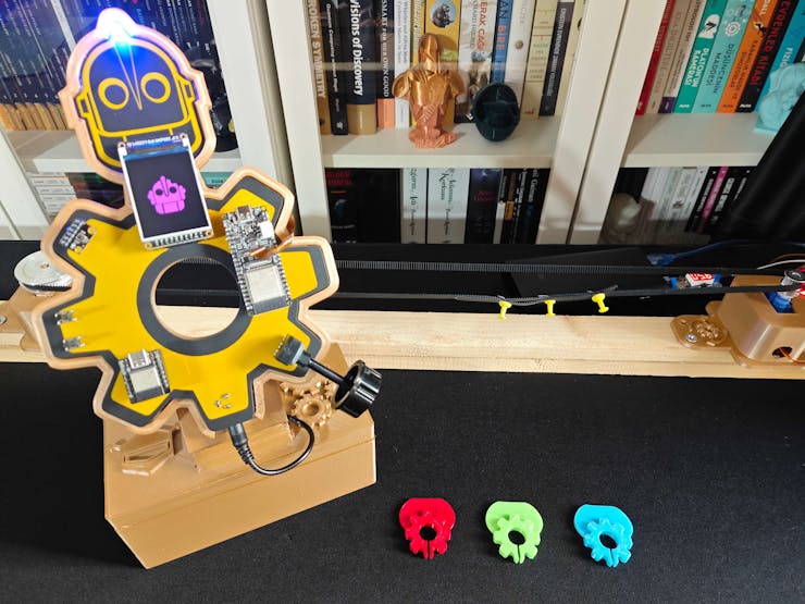
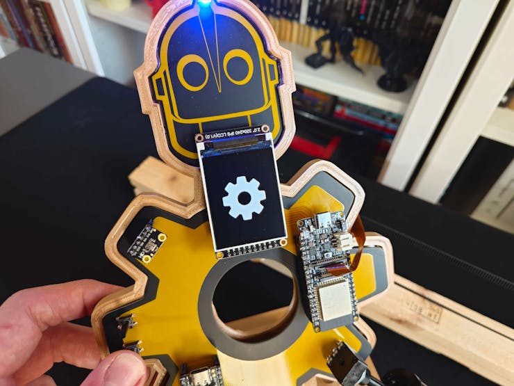
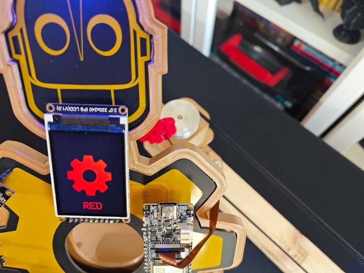
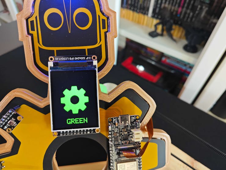
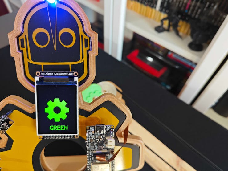
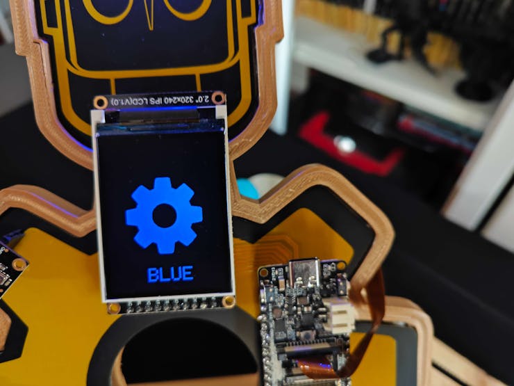
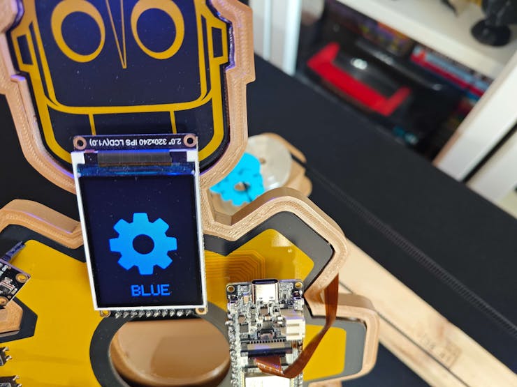
⚙️⚠️🔊📲 If the object detection model cannot detect a specialized component (part), FireBeetle 2 ESP32-S3 displays the Gear Icon as white on the Fermion TFT screen.
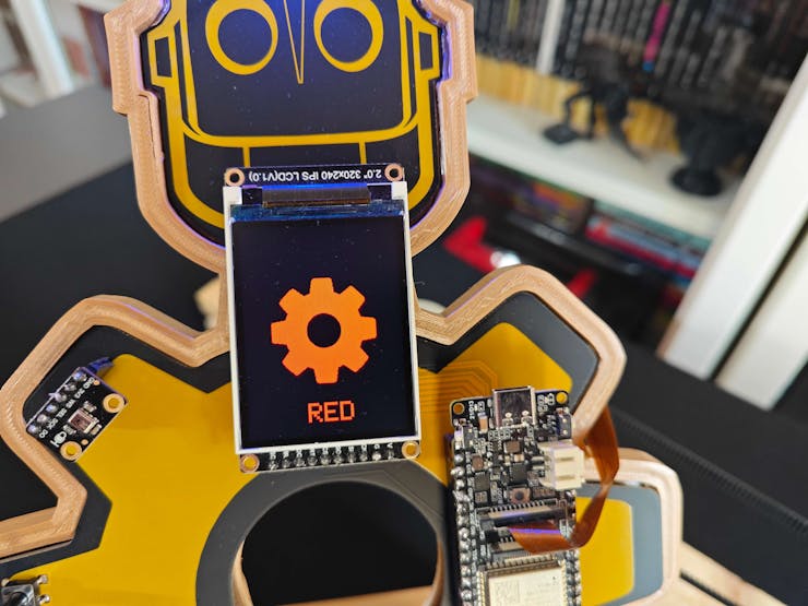
⚙️⚠️🔊📲 After detecting a specialized component representing a defective part causing mechanical deviations in a production line, FireBeetle 2 ESP32-S3 notifies the user by showing the Gear Icon with the assigned class color on the Fermion TFT display.
- Red
- Green
- Blue
![]()
![]()
![]()
![]()
![]()
![]()
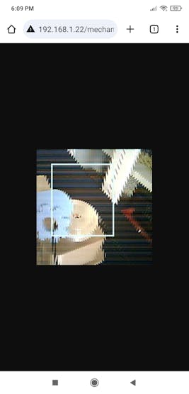
⚙️⚠️🔊📲 Then, FireBeetle 2 ESP32-S3 sends the model detection results, the bounding box measurements, and the resulting image (RGB565 buffer) to the web application via an HTTP POST request.
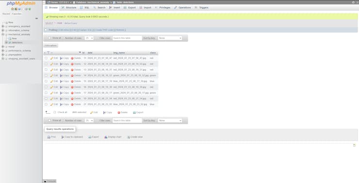
⚙️⚠️🔊📲 After obtaining the information transferred by FireBeetle 2 ESP32-S3, the web application:
- saves the results with the generated resulting image name to the detections MySQL database table,
- saves the raw image buffer (RGB565) as a TXT file,
- converts the saved RGB565 buffer to a JPG file by executing a Python script,
- passes the received bounding box measurements (via GET query parameters) as Python Arguments to the Python script to modify the converted JPG file to draw the model bounding box,
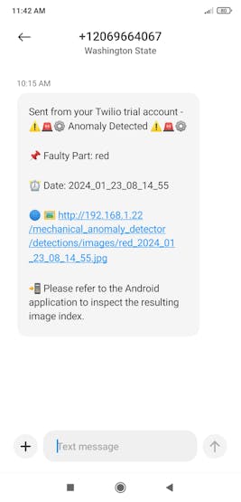
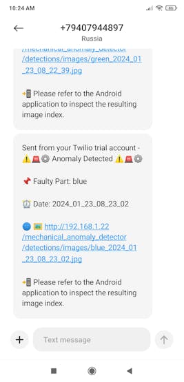
- then sends an SMS to the user's phone number via Twilio so as to inform the user of the diagnosed root cause (component), including the resulting image URL path.
![]()
![]()
![]()
![]()
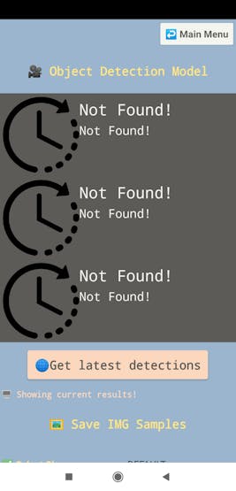
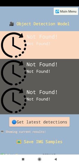
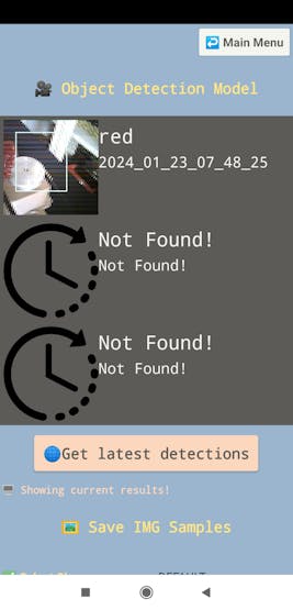
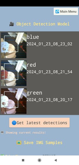
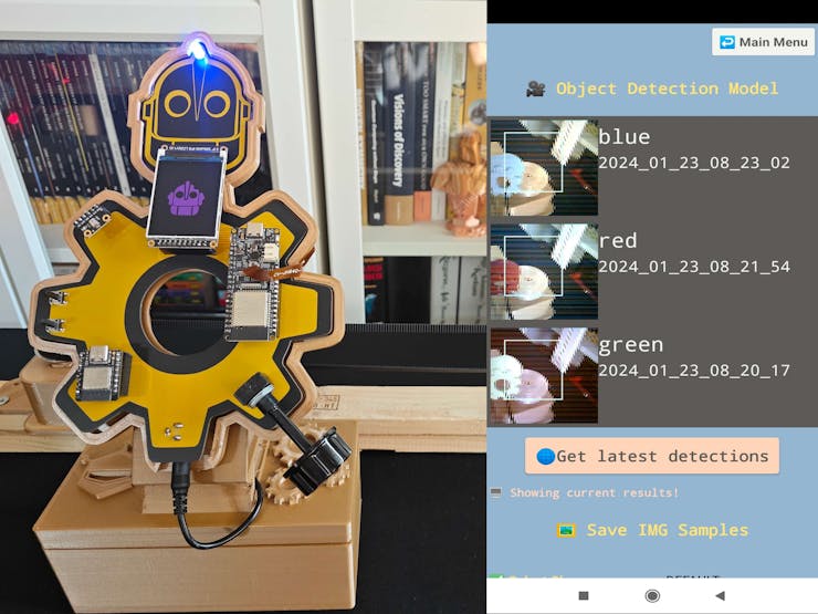
⚙️⚠️🔊📲 When requested by the Android application via an HTTP GET request, the web application yields a list of three elements from the data records in the database table, including the latest model detection results, the prediction dates, and the modified resulting images (URLs).
⚙️⚠️🔊📲 If there are not enough data records to create a list of three elements, the web application fills each missing element with default variables.
⚙️⚠️🔊📲 As the user clicks the Get latest detection button on the camera configuration section, the Android application makes an HTTP GET request to the web application in order to acquire the mentioned list.
⚙️⚠️🔊📲 Then, the Android application utilizes this list to showcase the latest diagnosed root causes of the inflicted mechanical anomalies on the camera configuration section.
![]()
![]()
![]()
![]()
⚙️⚠️🔊📲 Also, Beetle ESP32-C3 and FireBeetle 2 ESP32-S3 print progression notifications on the serial monitor for debugging.
![]()
![]()
![]()
After conducting various experiments, I obtained pretty accurate results for detecting sound-based mechanical anomalies and the specialized components representing the faulty parts causing deviations in a production line.
-
27Videos and Conclusion
-
28Further Discussions
By applying multi-model methods (audio classification and object detection) to detect sound-based mechanical anomalies and diagnose the root causes of the detected deviations, we can achieve to:
⚙️⚠️🔊📲 preclude detrimental mechanical malfunctions,
⚙️⚠️🔊📲 maintain stable and profitable production lines,
⚙️⚠️🔊📲 diagnose the crux of the system failure to expedite the overhaul process,
⚙️⚠️🔊📲 eliminate the defective parts engendering mechanical anomalies,
⚙️⚠️🔊📲 assist operators in pinpointing potential mechanical failures,
⚙️⚠️🔊📲 avoid expensive part replacements due to neglected mechanical anomalies.
![]()
-
29References
[1] Anomaly Detection in Industrial Machinery using IoT Devices and Machine Learning: a Systematic Mapping, 14 Nov 2023, https://arxiv.org/pdf/2307.15807.pdf.
[2] Martha Rodríguez, Diana P. Tobón, Danny Múnera, Anomaly classification in industrial Internet of things: A review, Intelligent Systems with Applications, Volume 18, 2023, ISSN 2667-3053, https://doi.org/10.1016/j.iswa.2023.200232.
[3] Industrial Anomaly Detection in manufacturing, Supper & Supper, https://supperundsupper.com/en/usecases/industrial-anomaly-detection-in-manufacturing.
-
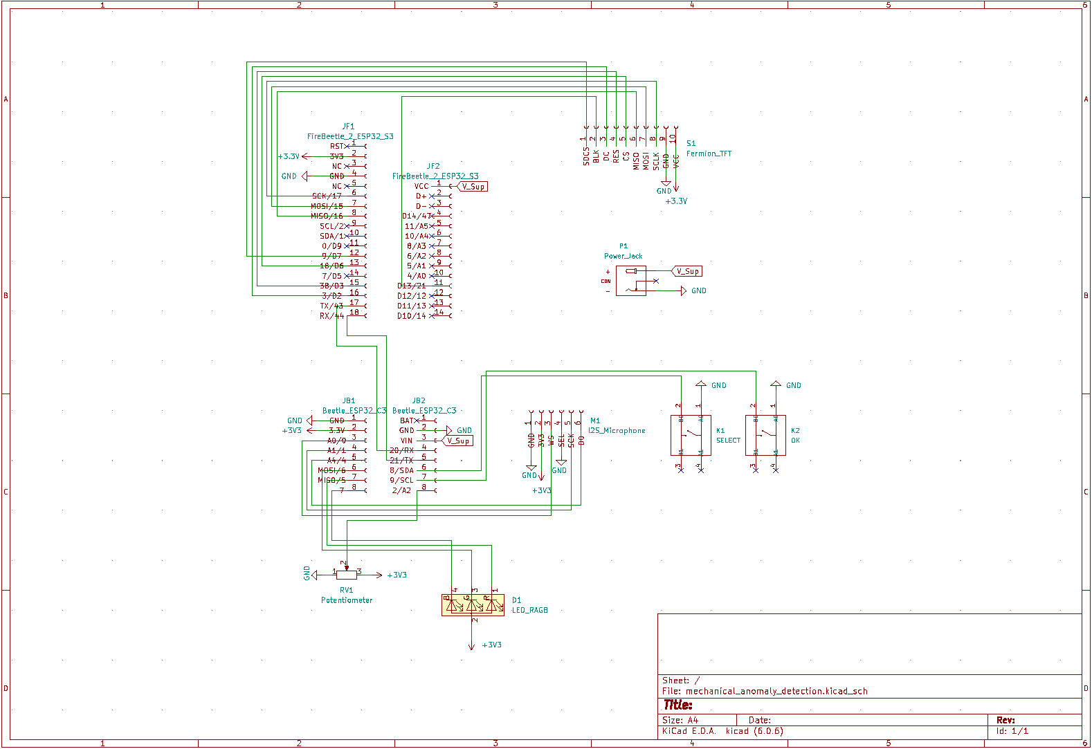
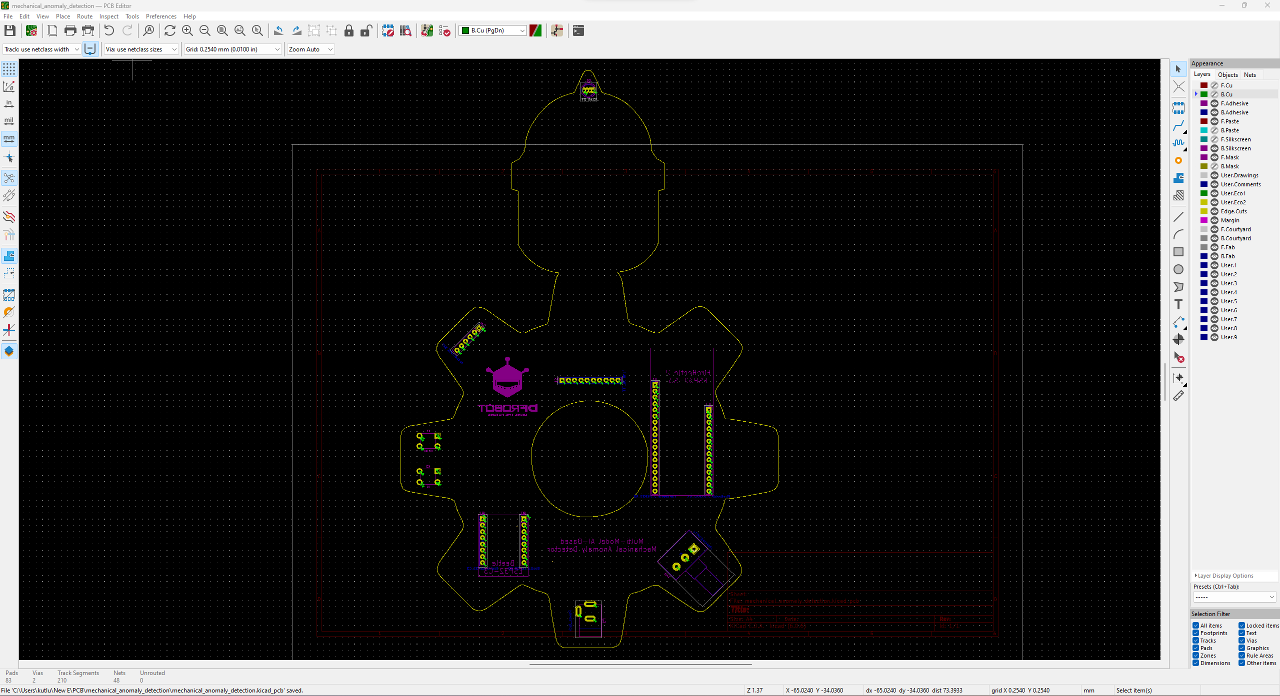
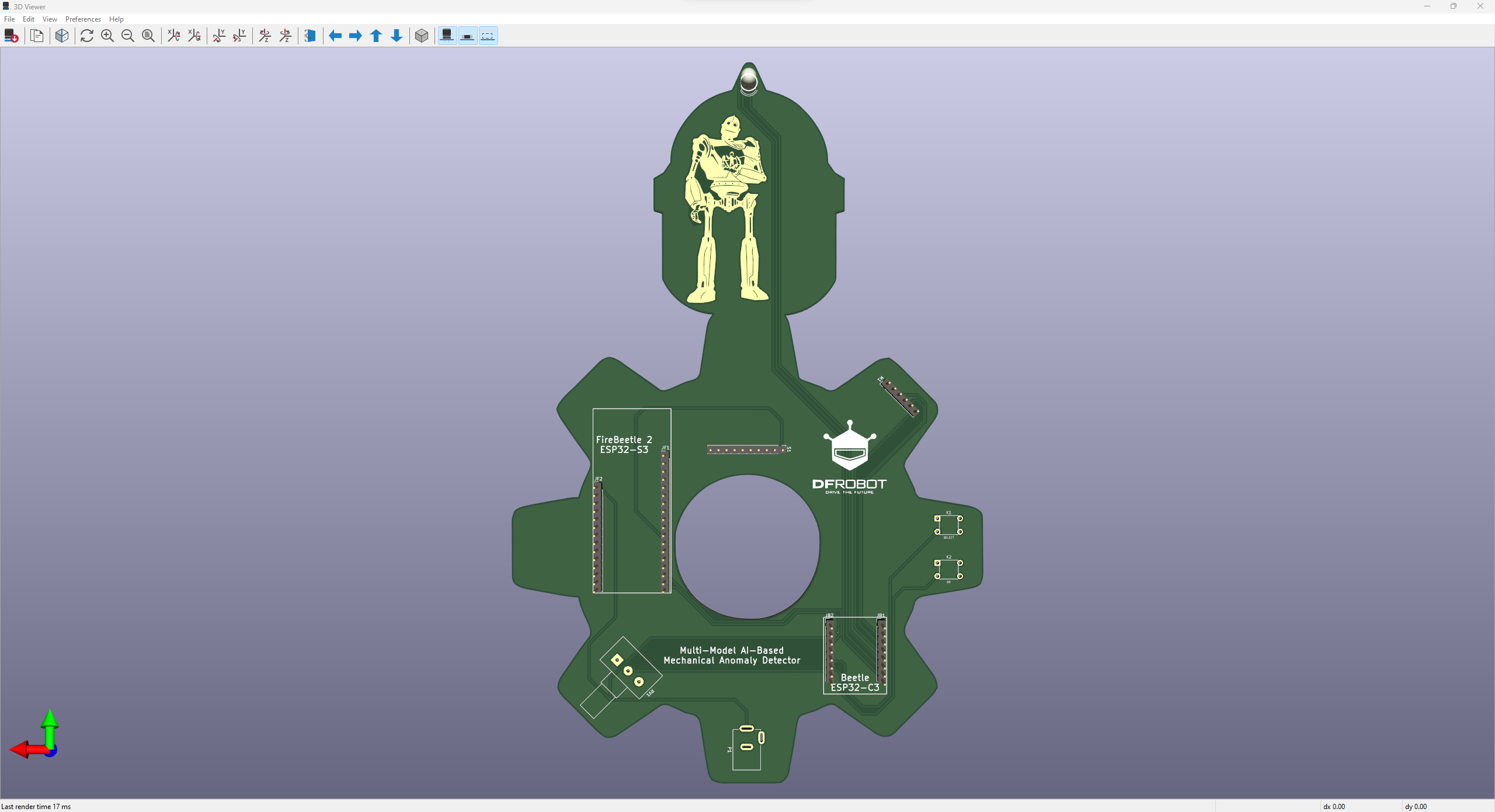
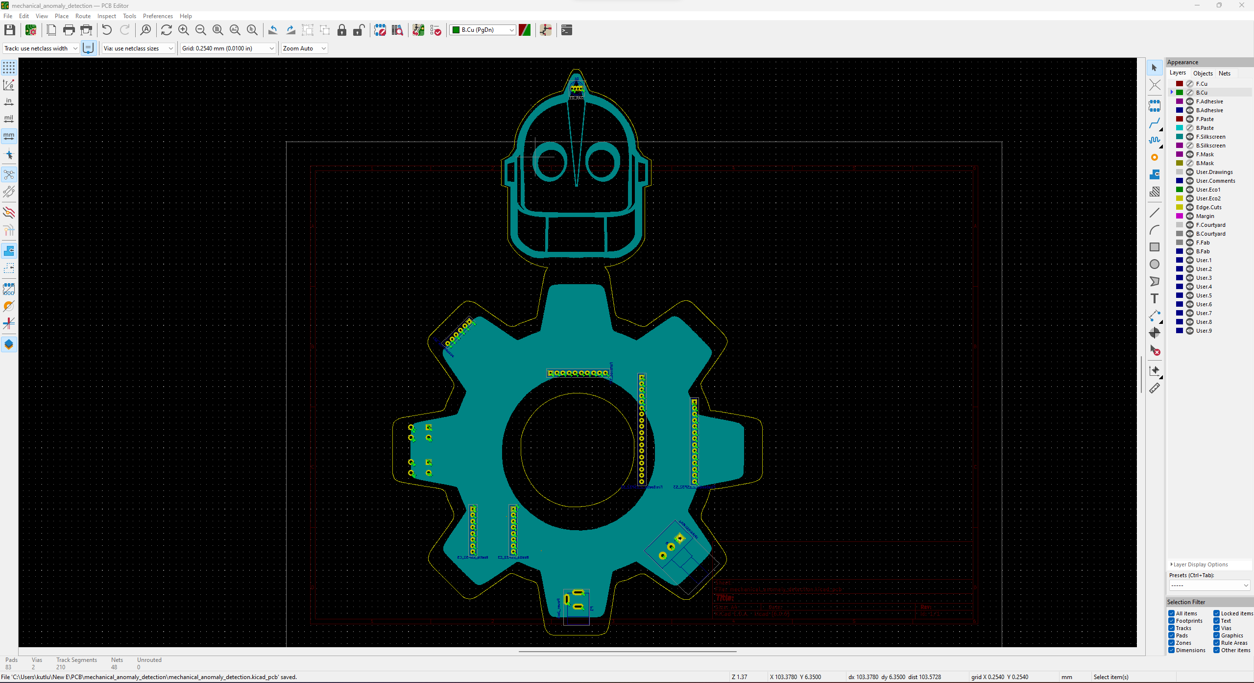
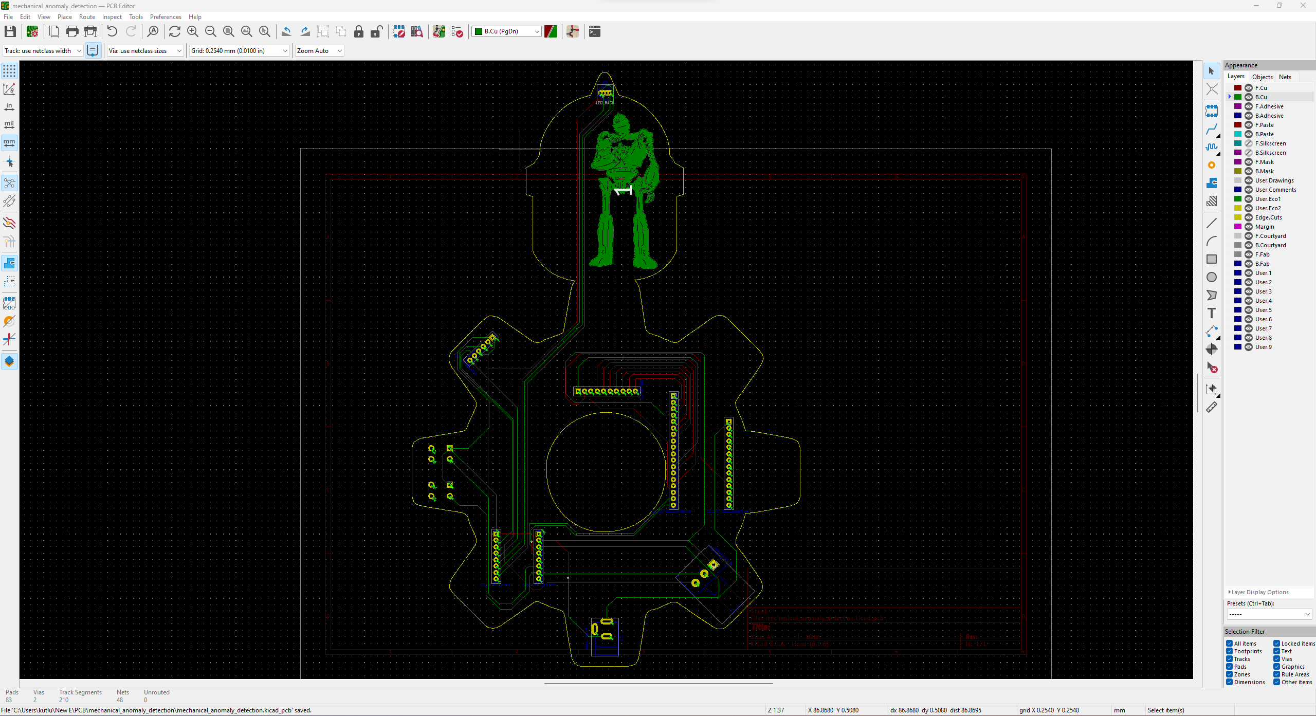
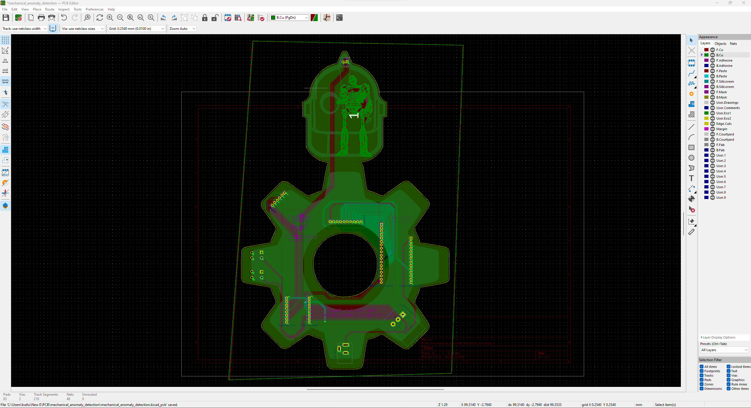
30Schematics
![]()
![]()
![]()
![]()
![]()
![]()
![]()
![]()
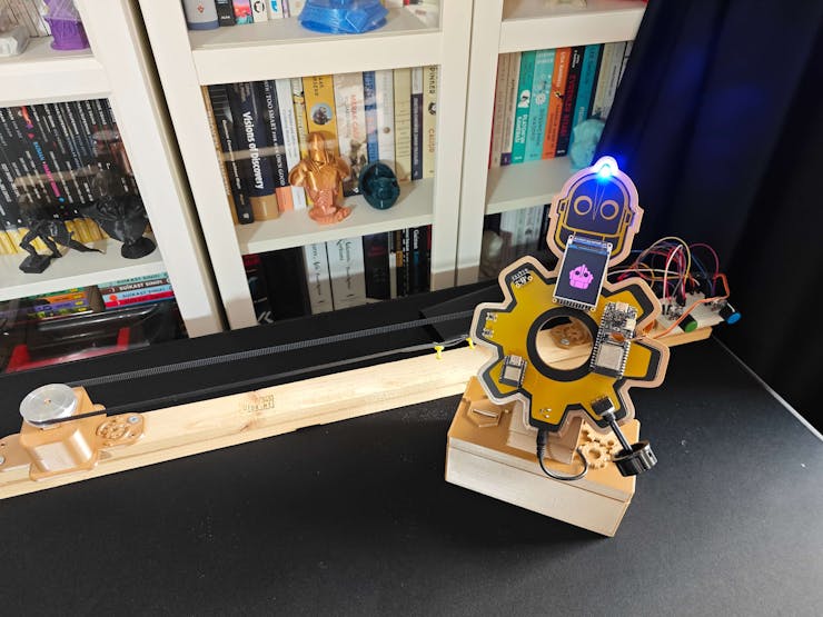
Multi-Model AI-Based Mechanical Anomaly Detector
Apply sound data-based anomalous behavior detection, diagnose the root cause via object detection concurrently, and inform the user via SMS.


Discussions
Become a Hackaday.io Member
Create an account to leave a comment. Already have an account? Log In.