Ted Yapo
-
Remaking the original
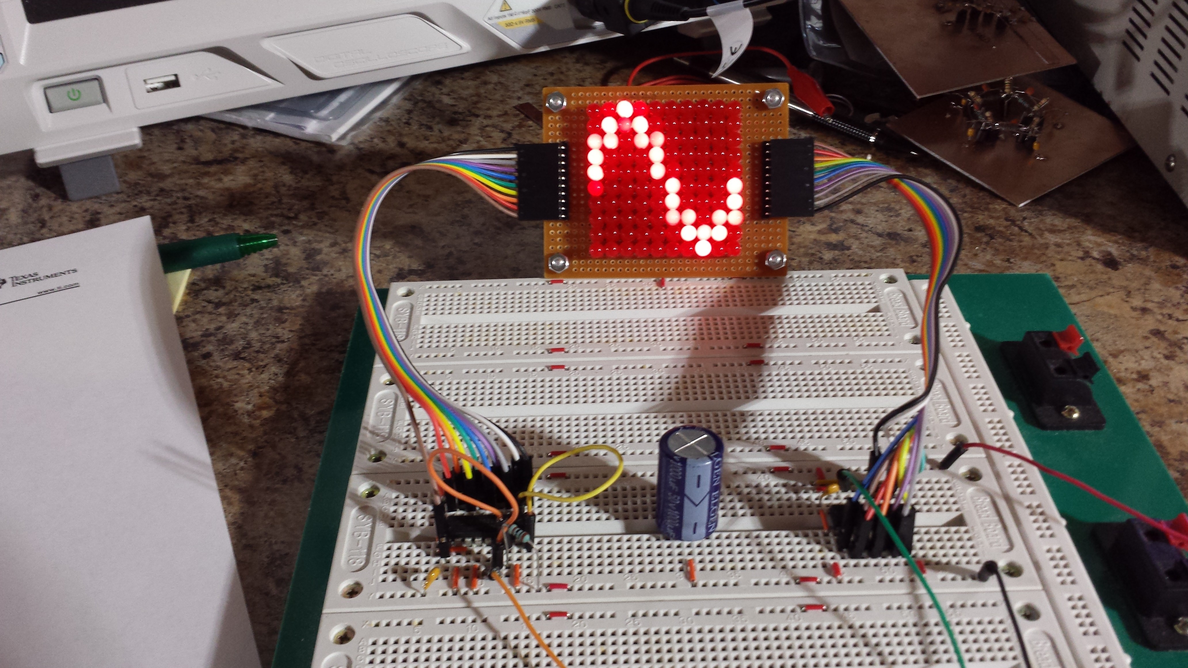
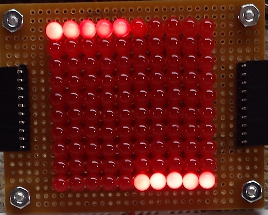
01/29/2017 at 19:54 • 12 commentsI saw an email notification that my 10x10 0603 LED PCBs are supposed to arrive Monday. This inspired me to make a 10x10 with 5mm LEDs so I didn't have to wait. Some parts were just as much of a pain as when I first did it 30+ years ago.
![]()
One of the issues was the little lip at the bottom of the LEDs - this keeps them from packing closely together. I know you can get LEDs without the lip, but I used what I had at around midnight last night. Just as I had done before, I ended up filing this lip off each LED, which took most of the time. The soldering fun more than made up for this inconvenience.
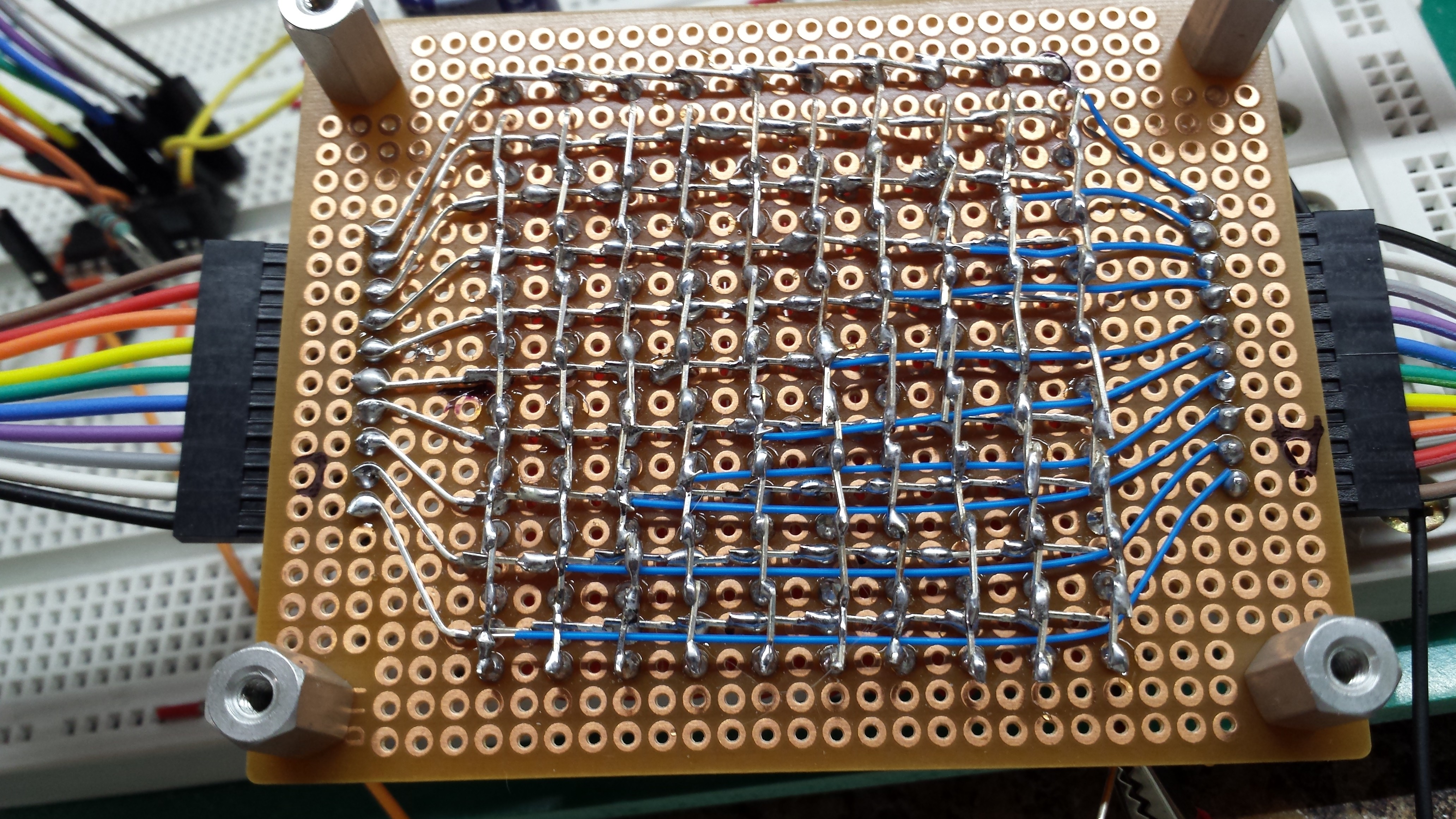
The matrix is connected underneath, with the connectors brought out to 0.1" headers, like on the PCBs:
![]()
After assembling and testing the board, I've determined that I have about a 1% error rate in inserting LEDs correctly. One of them got soldered in backwards, and I had to unsolder the neighbors to replace it. Not too bad, I guess considering it was a late-night adventure.
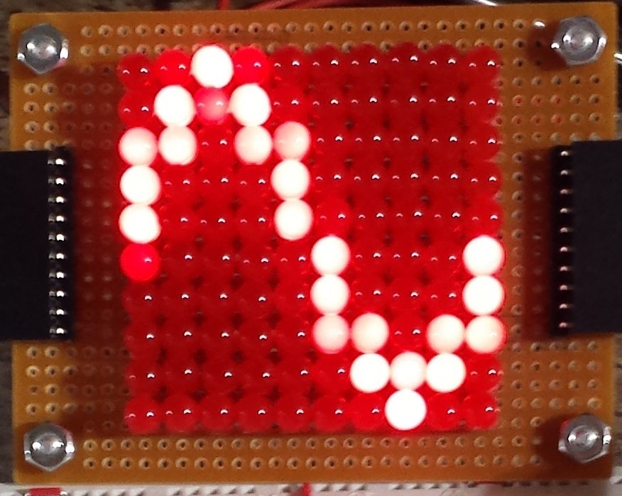
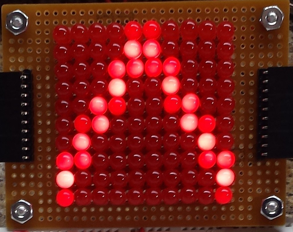
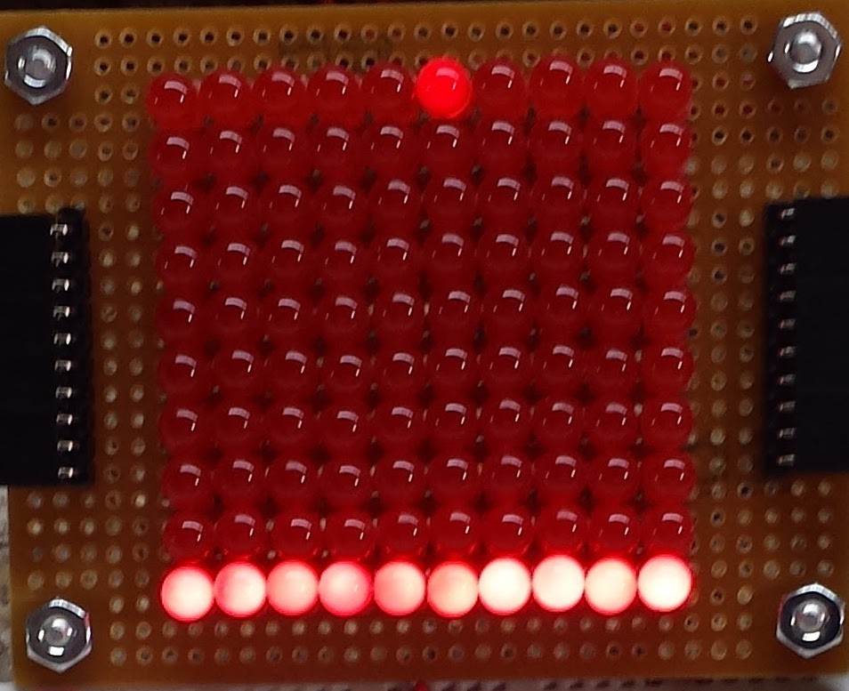
The test driver uses an LM3914 to drive the vertical and a 74HC4017 to drive the horizontal sweep. Using a dual-channel DDS to drive both makes testing a breeze. With the horizontal set to 10x the vertical frequency, the display is rock-stable, since the DDS outputs have a constant phase relationship. Here are sine, triangle, square, and pulse waveforms displayed:
![]()
![]()
![]()
![]()
I found that the LM3914 seemed to start skipping LEDs with a sine wave of about 50 kHz or above. I seem to remember them being faster before - although this one was an ebay purchase, and could be a fake, I guess. For audio frequencies, this seems like it would be fine. I'd like to go 1000 times faster :-)
The display is about how I remember it - due to the low resolution, a slowly-scrolling display seems easier to visualize than a steadily-triggered one. By setting slightly different frequencies at the DDS outputs, crawling displays can be made, too. Here are the same waveforms in motion:
Comparing this to the build from my teens, I have to admit, some of the magic is gone. I still remember the first waveform I saw on the thing - it was 60Hz power-line hum. I left the thing on overnight like a night-light with that slowly-crawling sine on it.
As with most things, the cure here may simply be MORE LEDs...
-
First test: 10x10 display
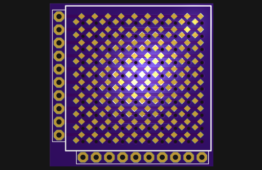
01/17/2017 at 17:31 • 0 commentsI figured I'd start small - I haven't used 0603 LEDs before, so I ordered some cheap ones off ebay and designed this board:
![]()
The LEDs are on a 100 mil grid, which makes the connectors easier. I probably should have used smaller vias, but at least I tented them, which should help avoid shorts. In the next iteration, I'll shrink the vias a little.
The display is 10x10, which will allow me to re-create the original circuit as a first step. I have some 74HC4017's which are a definite improvement over the original CD4017 and even some LM3914's kicking around. I won't bother with any of the analog front end, and will probably just drive the clock and analog inputs from a 2-channel bench DDS generator to see some waveforms on the LEDs.
I'm also realizing that larger displays might not fit in the light version of Eagle. At 0.1" pitch, a 32x32 display is 81.28 mm wide, which is more than the 80 mm Eagle light version limit. I could get away with a 24x32 display in 80x100mm, though. That's 768 LEDs - a challenge to populate by hand. Fun.
-
Basic LED scanning design
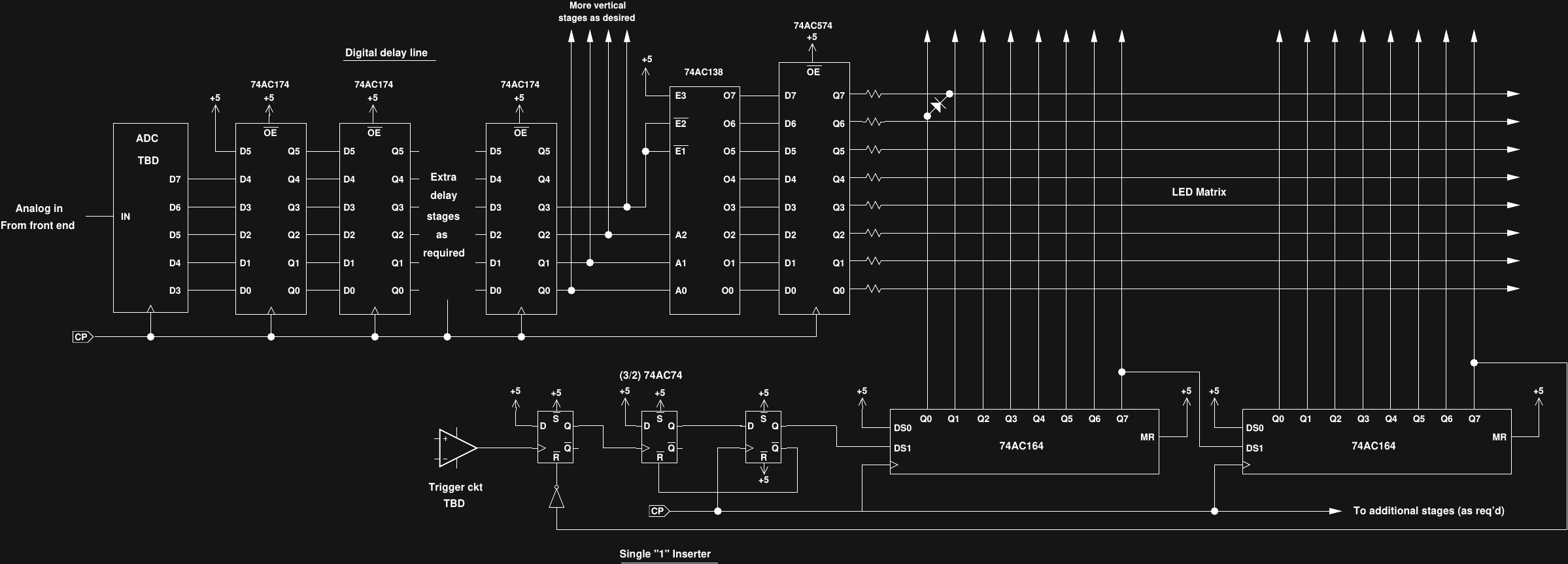
01/16/2017 at 20:47 • 5 commentsHere's a first sketch for the digital parts of the design (a pdf version can be downloaded here).
![]()
The horizontal sweep is done with a series of 74AC164 8-bit shift registers, so the horizontal resolution can be expanded in multiples of 8 columns (you can also use less than 8 columns on the last register). This method is faster and easier than a decoded counter, but requires that a single "1" bit is inserted into the shift register to start each sweep. Three 74AC74 d-flops form the inserter, which starts a single "1" bit rippling through the columns when the trigger input goes high. No retriggering is allowed until the "1" exits the shift register.
The vertical driver starts with a flash or pipelined 8-bit ADC. I haven't chosen the exact ADC yet, but the AD9057, and AD9293, and ADS831 are on the list to consider. The lowest few bits out of the ADC are discarded, and the most significant four or five bits (depending on the chosen vertical resolution, TBD) enter a delay line made from 74AC174 d-flops. This delay line keeps the trigger point on the display, as opposed to being off the left edge - in classic Tek scopes, an analog delay line served the same purpose. In this case, it centers the trigger point, but doesn't let you adjust the horizontal position - which is fine with me. Depending on the display size and the amount of pipelining inside the ADC, a different number of delay stages will be required.
The output of the delay line is decoded into a 1-of-N active-low output by a number of 74AC138 decoders (added as required for the number of display rows desired). The 74AC138 allows up to 32 outputs to be decoded (4 ICs) without additional logic. These decoders feature active low outputs, which make the row lines the LED cathodes. A number of 74AC574 d-flops register the outputs of the decoders and drive the LED matrix rows through a set of current-limiting resistors.
The 74AC logic gates will drive 24mA, which should be enough to light high-efficiency LEDs to a decent brightness. Even though the LED matrix will be large, only a single LED in each row and each column is lit in any "frame", so I'm guessing the brightness will be OK.
I'm thinking of prototyping a 1D version that just shows a digital signal on a line of LEDs to test the horizontal sweep circuit.
I'm still thinking about the timebase. DDS is easy, but getting one that goes up to 80 MHz may be expensive. A 100 MHz oscillator with a chain of divide-by-2 and divide-by-5 counters would make a decent 1-2-5 timebase, although with a lot of components.
I'm also still thinking about the analog front end and trigger circuit. I might start with a 50-ohm front end for simplicity, then add a high-impedance buffer of some sort.