 TheBrokenEngineer
I know some people love this stuff and I know that this is necessary before going to copper boards but it is really something that I do not like all that much.
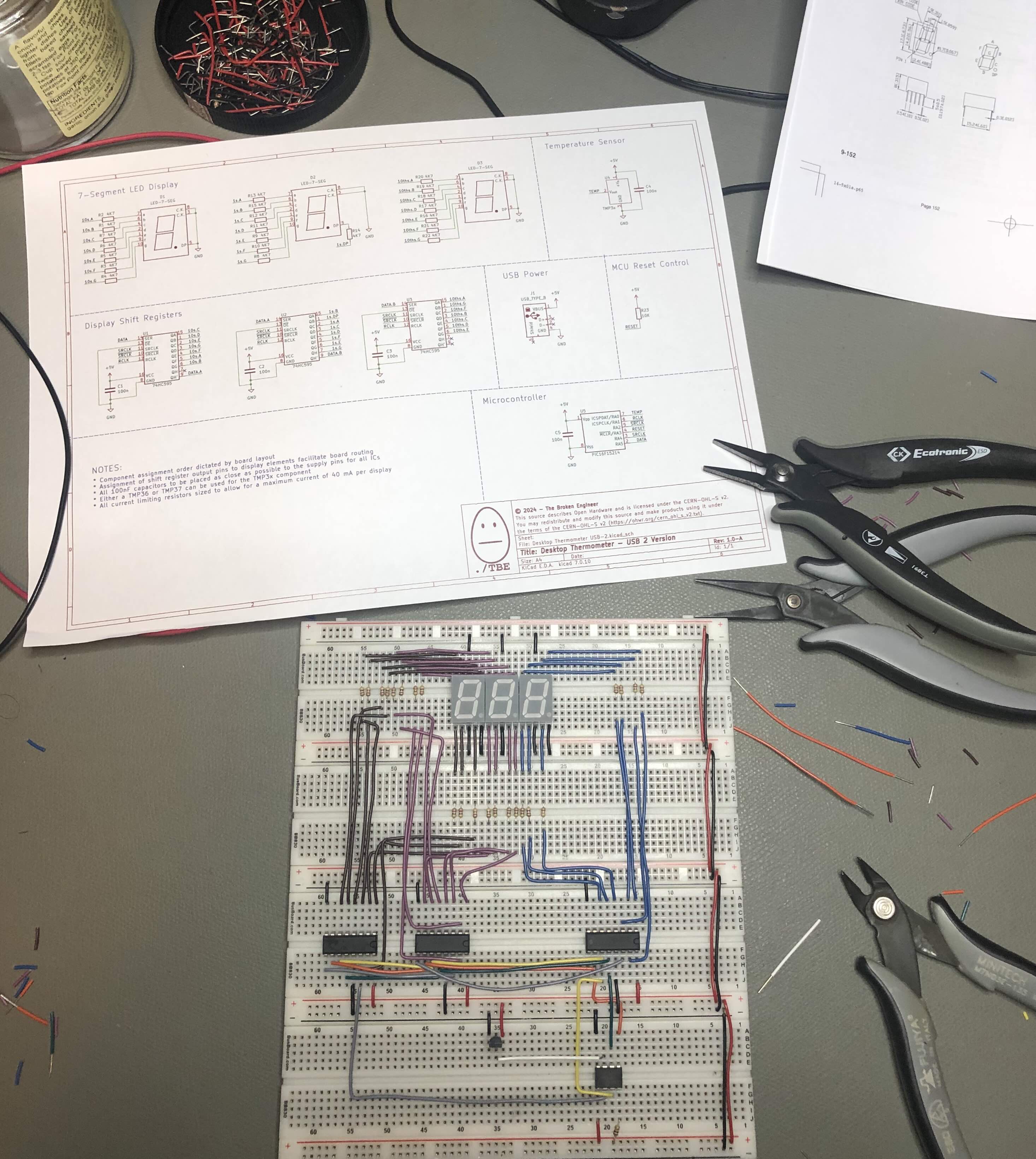
I think the thing about it is that I design the schematic in such a way that it is easy to lay out and route the traces. The down side is that when making this up on a breadboard, nothing seems to line up in a great manner.
In any event, the prototype is all wired up (hopefully correctly) and now all that is left is to connect the debugger and test the code I have written to see if the board is wired correctly, I have wired the breadboard correctly and have actually written code that works. So many places where this could go wrong, so little brain power available to fix it.
Will be interesting to see what happens....as they say in the television business....stay tuned!
Discussions
Become a Hackaday.io Member
Create an account to leave a comment. Already have an account? Log In.