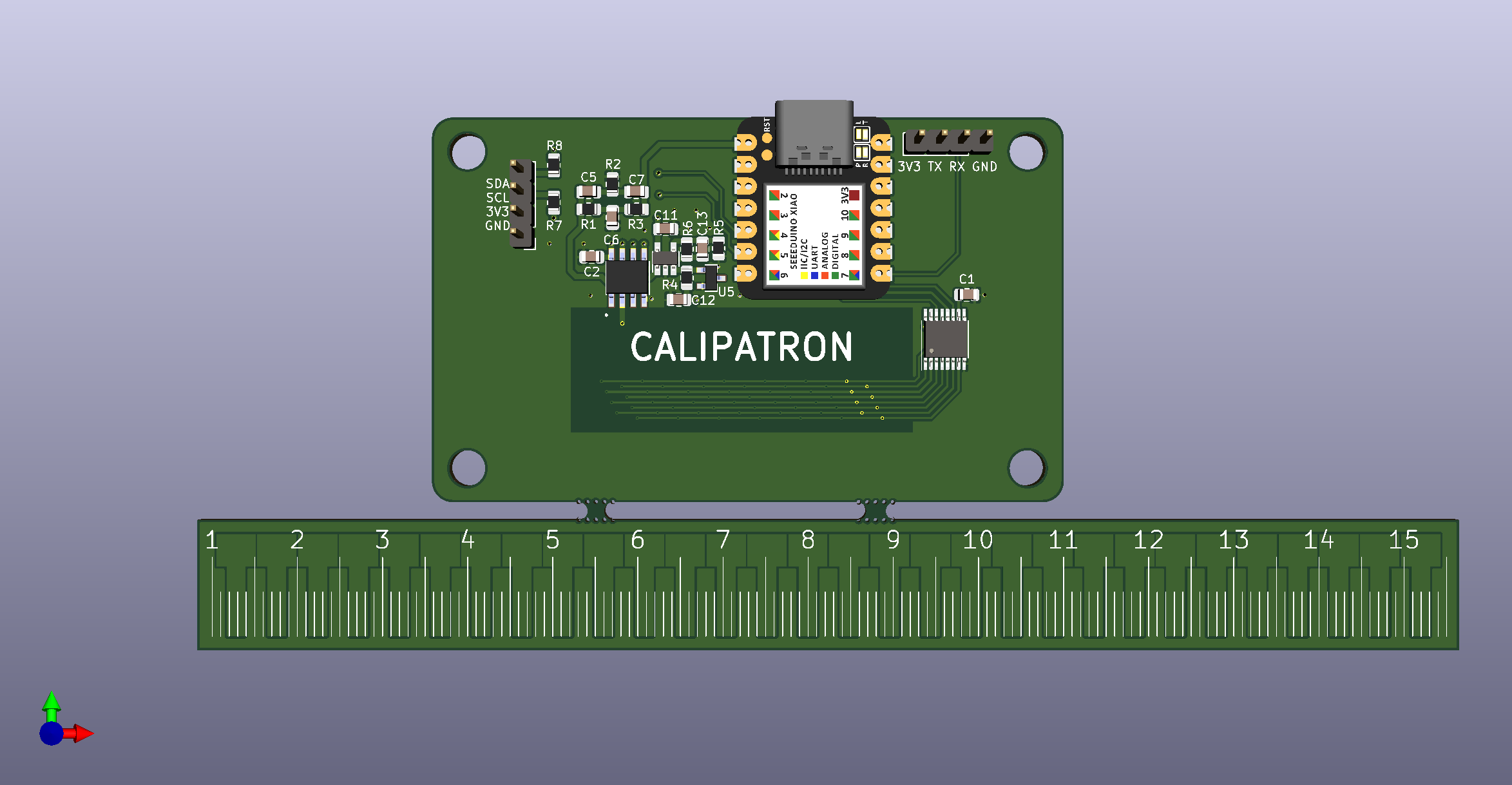
I design my own digital caliper based on STM32F103 blue pill (and more).
To make the experience fit your profile, pick a username and tell us what interests you.
We found and based on your interests.
Hi all,
Many people have asked me for the project and since my time on the project is limited it would be a shame not to share what i have done so far with the hopes that someone will pick it up and make it better.
Here is the link:
https://github.com/MitkoDyakov/Calipatron/tree/main/Hardware/V2
Hi all,
Jay remaindered me about the patents and I went to search in them for answers.
Good news / bad news type of situation.
Bad news: I still don't know the answer of any of the questions from last log.
Good news:I found the answers to a questions I did not ask.
Does the size of the pattern matter and how?
In short - yes. You can think of it this way - 0.01 mm out of 1 mm is far greater than 0.01 mm out of 2.5mm. Smaller pattern greater sensitivity.
What are those capacitors on the back for?
Hello all,
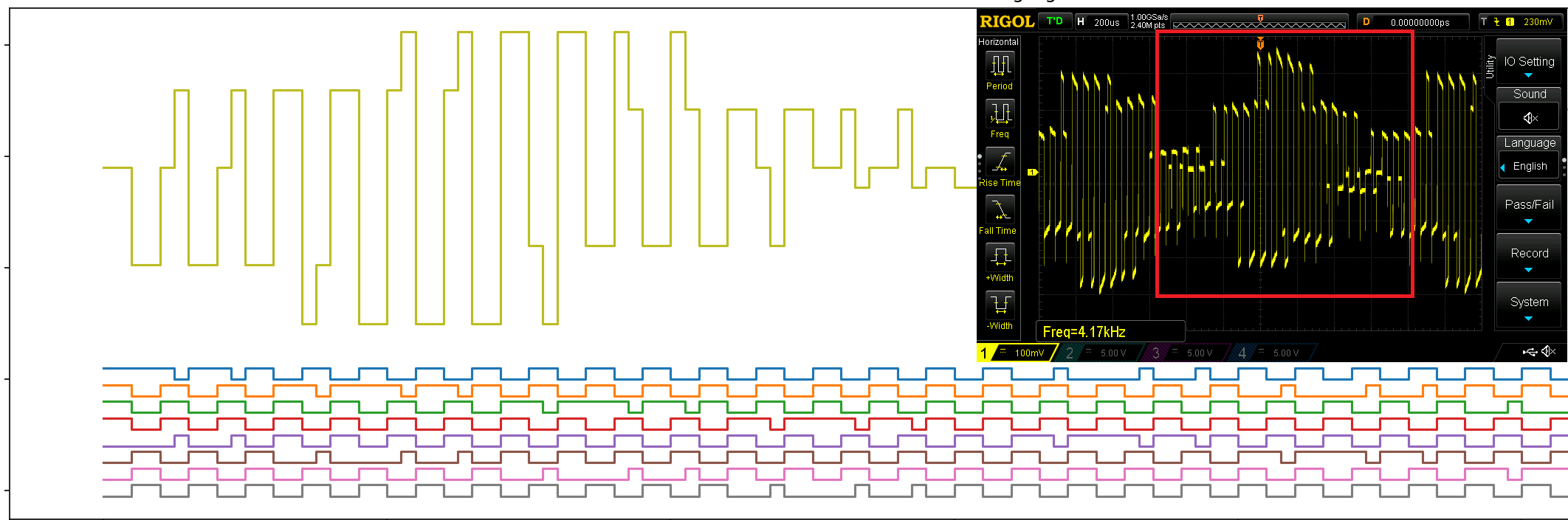
Another session with ChatGPT and some googling I made a short python script to generate the patter that we use for excitation of the sensor. The code is already uploaded for you to play with
Hello all,
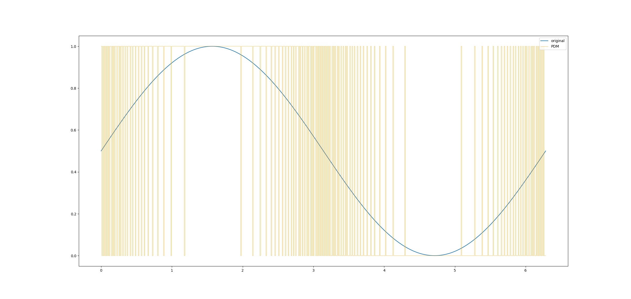
I have decided to do something that probably I should have started with. A simulation!
Here you can find a python script that uses matplotlib to graph the excitation signals and the resulting signal.
It is not very sophisticated, but it seems to match the real world to a great extend.
Hello all,
The project is still going! Lately I have been overwhelmed with some personal issues and did not have much time to tinker.
However quite a number of people have contacted me about the project and expressed interest. So this motivates me to keep going.
There are still some open questions regarding the project.
1. How is this signals generated? Why this frequency? It looks like PDM but not quite.
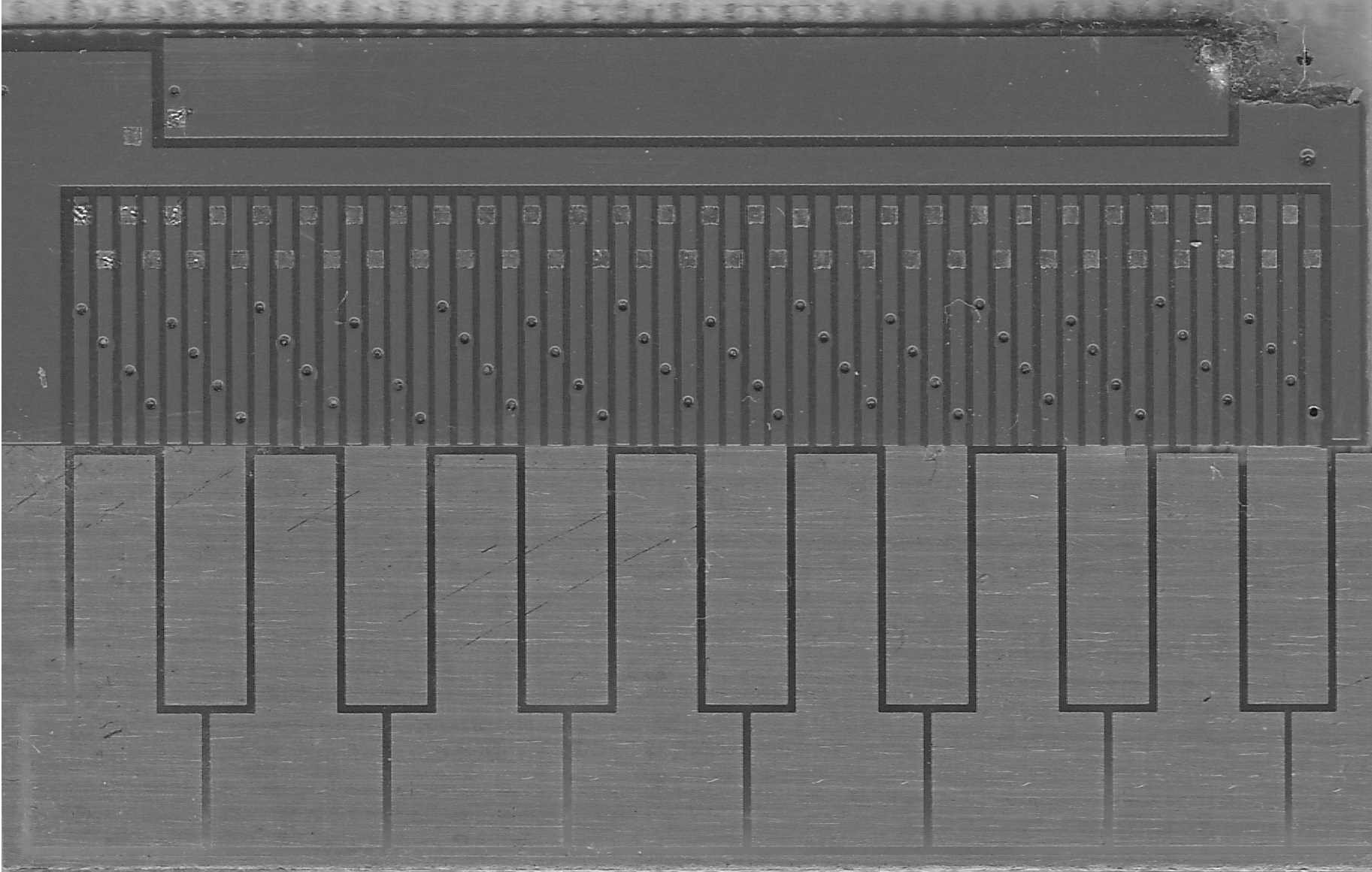
2. My footprints do not match the ones form a caliper I bought. The example pads do not align as neatly as mine. I put both scale and sensor on my scanner and this is the result. Why do they did that?
Hello all,
You may know Kevin Lynagh form "I made a cell phone" talk (and many more places), he has been interested in the project on the software side of things. He made a breakdown of his implementation of the SW.
You can take a look here: https://kevinlynagh.com/calipertron/
Happy new year to everyone!
Cheers,
M
Hello all,
There are a few people that were interested in the project. It would not be very fun if you don't have hardware to tinker with. So you got two options.
A - Is to get the files gerber files and the BOM from the repo and make yourself a board with the STM32
B - You can order a Type 2 kit from my tindie shop
There are a few differences to consider A is cheap to make. It is only 2 layer PCB and you can scavenge a blue pill to take the parts. But this comes with a cost of lower resolution.
Example B is a bit nicer you can choose what XIAO board to use and it better resolution. But it is 4 layer board and a bit more expensive.
Cheers,
M
Hello all,
This is how the fix looks like
Now it looks quite bad, but it works kind of good. This is wat we have now on the ADC pin of the XIAO
Now there are a few differences. Because the excitation pads are smaller the charge on the them is smaller and the useful signal is smaller. This makes the noise to signal ration bigger. And this is why we see a bit fuzzier signal.
The high part of the signal is sloped. My theory about that is there is a bit of overshoot on the excitation signals. This is normal since I soldered a bunch of signals.
A think when I put the shift register on the board this will be mitigated to a large extend.
Time for some KiCAD action.
Cheers,
M
Hello all,
I wrote on the previous build log that we have a different flavor of HW. For now we will call it type 2.
I was hoping that this would be just scaling the bigger footprints down and subtitling the MCU with headers, but it was not meant to be like that :)
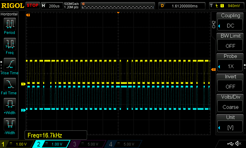
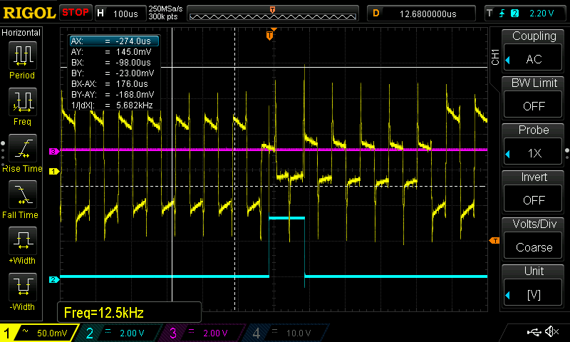
When I got the the hardware I saw this on the scope.
I was thinking at first it is noise from the switching of the PDM and I added some RC network to each pad. This only made the thing worse. Also I was thinking that the XIAO boards are noisy. Even I striped the copper surrounding the T-scale thinking that it was picking up some noise. The problem becomes obvious once we zoom in even closer.
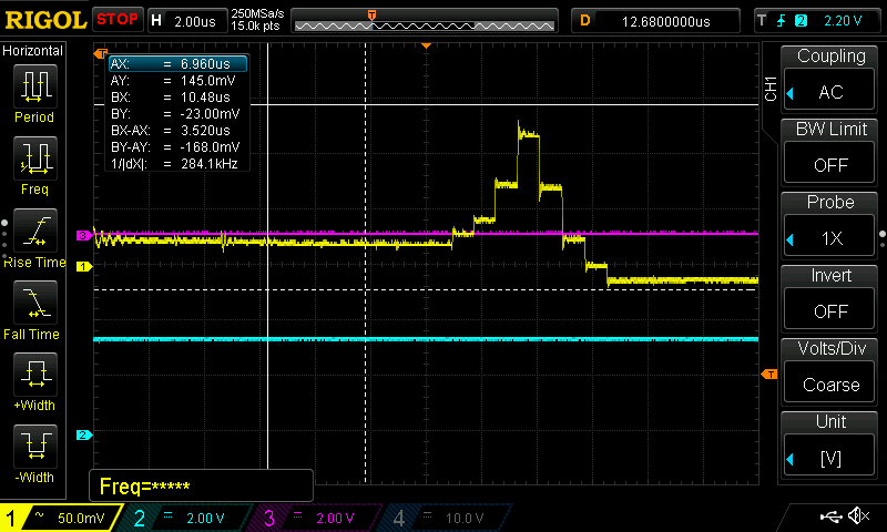
This is what one of those peaks look likes on the 2us scale. For the original hardware running the ST I was using port register to switch the state of the excitation pads all at once. But running the XIAO board I was switching them one by one and then we get this ladder effect.
Now the quick solution would be to do the same for the XIAO board, but not all the pins are on the same port. Further more what happens if we put RP2040 or other controllers. We need a way of switching everything robustly and with every MCU provided.
The solution for now would be to add a shift register like the 74HCT595D from NEXPERIA. I have some laying around and will make a test.
Also for bonus points a played around with the signal generation and I have modified the pattern a little bit so we get even nicer signals. You can get it from the repo.
Cheers,
M
Hello together,
Here you can find the necessary files to create your own boards. Since the design is two layer only it is possible to CNC the boards. You should only take care to isolate the back of the board where the scale is sliding with some tape:
Here is the link: https://github.com/MitkoDyakov/Calipatron/tree/main/Hardware/V1.2
You will find:
If you like the project and you want to join now is a good point. Still the project has a long way to go and it could be improved, but I feel the HW is in a working state and could be used in POC for your intended use.
Cheers,
M
Create an account to leave a comment. Already have an account? Log In.
You are correct, they are not a quadrature encoders. Encoders do not care about the distance between the rising edges of the A/B signal. They care just about which is first and the count. In our case we have syne waves and we care about not only which peak comes first but also when and how many crossovers there are. (Or at least this is my thinking)
I'm late to the game. Wondering what the current state of this project is, what blocking issues might remain, and how I might be able to help.
I'm actively working on a caliper project and have studied as much relevant info that I've been able to find.
Happy to contribute to this project if I can... Assuming there is still interest here.
Hi Todd, I have made everything open. You can find it on the github repo. More or less you can find the state of the project from the build logs. One big mystery is how the excitation pattern is generated. If you want I can add you as a contributor you are more than welcome. If you have your own thing going, please share a link.
Cheers!
I've been all over the logs and github but I haven't reviewed the code.I'll contribute any progress here. No need to do anything different.
I guess it's not completely clear what part of signal generation you haven't figured out. Is it how to determine the frequency/period or something else? I understand the simultaneous GPIO update method you used.
I did get confused by the log post on quadrature encoders. Vernier calipers don't use quadrature encoding. You can use two signals with 90 degree phase shift but that is a method to improve accuracy.
Could you please release the kicad files as well? I was going to try and build up a board with an STM32H7 - just to see if I could try and implement https://kevinlynagh.com/calipertron/ with better visualization using high speed USB on the H7
Hi Jay, you can find gerbers and schematics on the github repo. If you need the project files (KiCAD) you will have to wait a few days. I am on a trip, if I forget please DM me.
Thanks Dimitar, I will use the schematics posted on github - thanks for releasing all this info - this is awesome!
hi where is software?can i make this caliper by arduino?what is the code in arduino?/
tnx
We still don't have running example. Not long ago we where dealing with hardware issues. As soon as we get some viable example we will post it. Please stay tuned.
Being as obsessed with calipers as I am I'm totally going to make this one of my first projects I try with my new PCB mill. It looks like you're using capacitive touch or something very similar. I wonder if it would be possible to make the slide component double as a MIDI keyboard.
Actually it is 2 layers on the PCB, so CNC milling will be perfect. I would do digital MIDI trombone if I was you :D
DUDE that is freaking GENIUS! That is so much more badass and clever than whatever I would have thought up. I'm capable of making any changes that might make a milled PCB more reliable and will absolutely shoot them back to the documentation so they can be added if so. If there's any changes that are too complex for me I'll shoot them your way and you can decide if they're worth your time to either help me or do yourself. I don't expect anything so no worries there.
While I'm FAR from as capable on CAD as I should be by now I've been 3D printing since ~2011 (FDM and mSLA) so I'll take a crack at designing a printed enclosure to chuck back upstream as well. Once I have a useable stock board (unedited except for maybe small changes to make it more millable) I'll post and let me know if you want a couple, I'd love to be able to add to the project. The workflow I've been creating creates what I call "80% PCBs" (I actually think they're going to be better than 80% of what professional fab houses can do but it's kind of a play on the 80% AR receivers that can be completed at home legally, shut up I thought it was funny haha). They're milled, black or green (I prefer black but can do any color, black and green is what I have on hand though) solder mask applied then either laser or CNC etched (haven't decided which gives results i like better yet - oh yeah I have a laser engraver too), and the last thing I'm working on is the silk screening. Luckily that's an established, pretty easy concept I'm just trying to adapt the screen creation process to be laser cut for better results. I recently discovered that xTool offers a laser cut silk screening setup so I'm trying to figure out exactly what they use for their screen creation for the best laser cutting, although I'll probably end up buying their screen system as - though pricey - it allows multiple screens to be used with a single frame that stretches the screens out when locked in. Not having to have a seperate frame for each circuit design would be huge (especially with how relatively tiny PCBs are) as that cost adds up super fast. I'll update as I make progress, thanks for the warm welcome!
I love your enthusiasm!!! I am always down for a fun project, so send schematics, models etc. and I will review them. Note that I don't have formal educations about this, so I figure stuff as I go :)
Very interesting. I'll keep it brief... I'm one of the founders of a popular open source CNC firmware. When testing normal calipers I noticed that there's a huge time delay between the measurement and the actual position, rendering it virtually useless for motion control. It's probably because there's no need to have a fast measurement. What I'd like to see is if I can combine the timing of the diy caliper with (fast) motion of a known frequency and time delay. I'm particularly interested in a linear encoder here, ideally absolute, but response time is key here.
I am aware of glass scales and rotary encoders. They all have their advantages and perks.
If you have a design with schematics and some pcb's somewhere, I'm happy to just order a few and test it out. Also feel free to drop a message.
I'm curious exactly what kind of delay you're talking about, because my Mitutoyo calipers seem pretty instantaneous. If you're talking micro-seconds though that's entirely moot as my dumb meat eyes can't even detect that fast.
The cnc firmware i work with has a step rate of 125 kHz. Not even my mitutoyo calipers give data at that rate. I need to know the delay between motion and measurement, the delay between measurement and data (observation) and information about the consistency/delay of the timings.
I'm really excited about this project too! Would it be a good time to try reproducing it? I'd like to see if it can be made slightly smaller, and used as an encoder for a linear axis. Looking forward to future updates. :)
Thank you for the comment, we have a new version of the PCB. I am going to test it next week and if all is fine I will post the schematics and the gerbers on the git repo for everybody to play with. I do have a few extra board I could send your way if you want to join the project. Just send me a pm.
Thinking about the mechanical stiffness issue. I propose trying to bond the pcb to a piece of glass with superglue or uv cure.
I remember watching this [video](https://www.youtube.com/watch?v=c7A6QDj5Lbw) by diffraction limited showing that glass is surprisingly flat and looking it up on ebay it doesn't seem prohibitively expensive.
Love the project btw! Very interested to see how accurate the diy digital calipers can get.
The glass would defiantly work for the flatness, but there are more things to take into account such as alignment and repeatability in movement. And to be hones its remarkable how much stuff I drop on a daily basis, so the glass will take a beating. On the mechanical front Ryan made a lot of progress.
Thank you for the comment, we have a new version of the PCB so stay tuned.
If you get rid of the edges, simple U or square aluminium extrusion profiles are also remarkably straight. Looking forward for the new PCB, I have a nice application in mind where this could be very useful.
Become a member to follow this project and never miss any updates
Well...
A correction from me. I said vernier calipers don't use quadrature encoding. Actually, some do. But I don't believe that it is the common way.
Quadrature encoding has been used as a method to reduce or eliminate the accumulation of error vs distance for example.
But the various calipers in teardowns I have seen, and the majority of the papers I have read, don't.