-
1Sync the door remote to the garage door opener
Follow manufacturer instructions on sync'ing your new door remote with the garage door opener - make sure you test it out before you begin.
-
2Prep the garage door remote
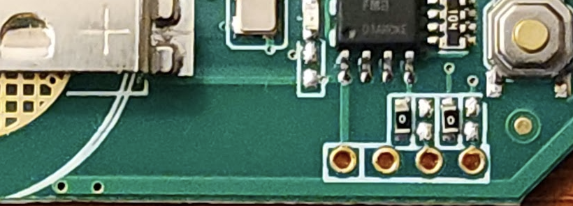
Open the outer casing of the ASONPAO IntelliCode remote, remove the board (it has no screws - it should lift out), and remove the CR2032 battery. Next to the button you should see four open pin holes: the one with the white box drawn around it and the thicker lead is the Vcc pin - we can consider that PIN0. Next to it is PIN1 - that is ground. The two farther to the right in the image are PIN2 (door button #2) and PIN3 (door button #3).
Solder pins into the open sockets for PIN0, PIN1, and PIN2. You can solder a lead for PIN3 if you like and have room on the breadboard.
![]()
-
3Wire the breadboard
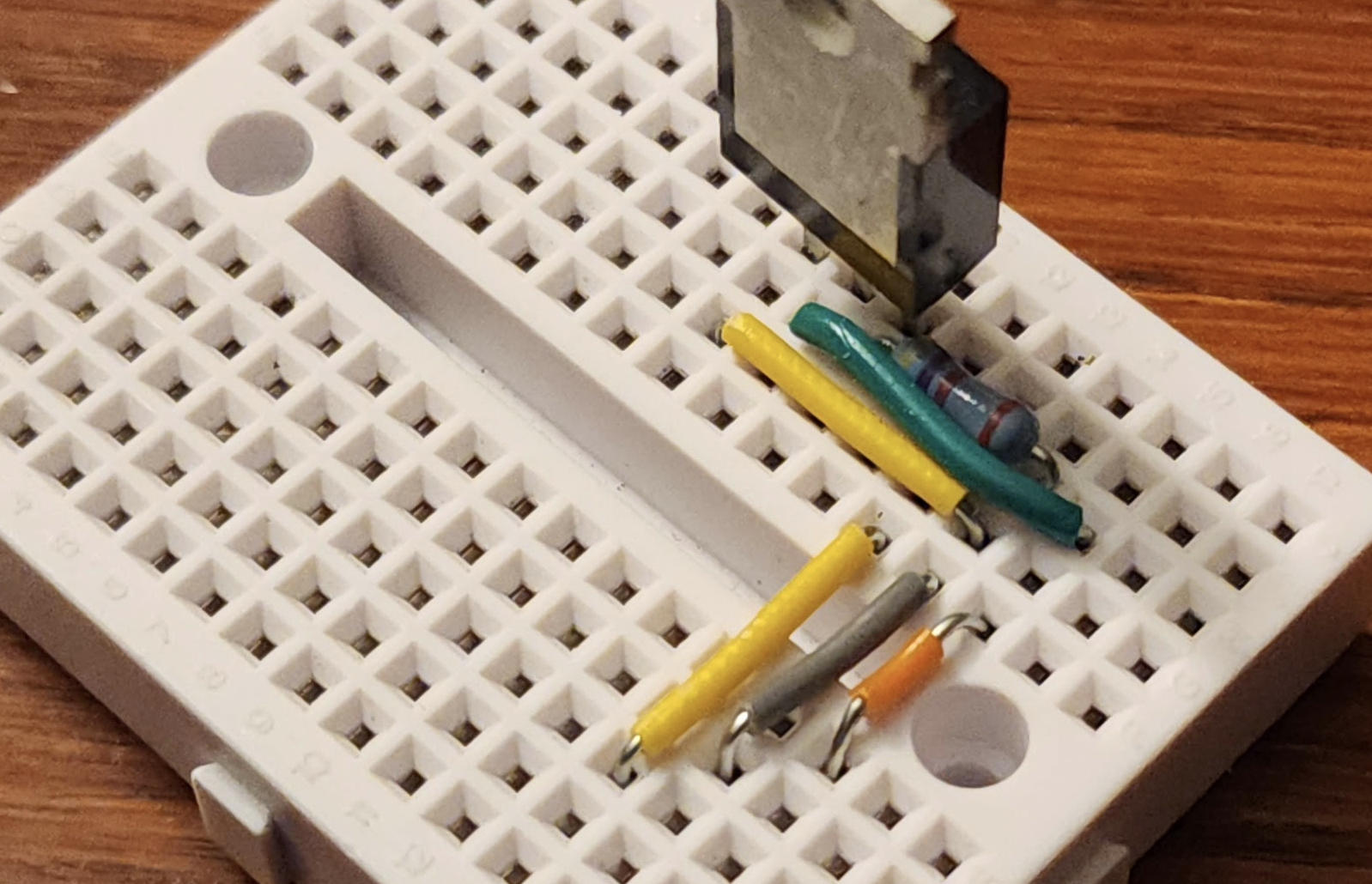
This step could go any number of ways - I chose to use a mini breadboard & jumper wires to the three pins soldered onto the remote.
PIN0 will go to a 3V wire, PIN1 to ground, and PIN2 to the drain of a MOSFET I had sitting around. The source of the MOSFET is ground (shared with PIN1), and the gate will be a wire to a GPIO pin on either a Flipper Zero or Raspberry Pi.
![]()
-
4Test GPIO remote
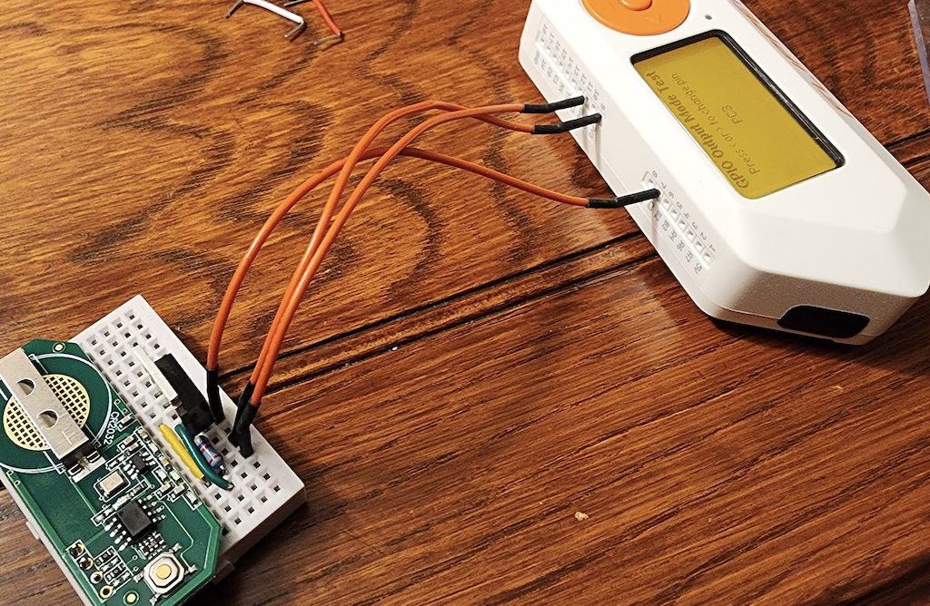
I used a Flipper Zero to test the remote, but a Raspberry Pi or Arduino would do as well. Confirm your switch and power works as expected.
![]()
-
5Provision the SQS Gateway
Create an AWS account if you haven't already, and then use the SQSGateway app to provision an API Gateway, SQS queue, and an API key in your AWS account. I think the services provisioned as part of this step should fit within the free tier, but always double-check. I don't think I've had a (personal) AWS bill over $3 in the past few years, but milage may vary.
Follow the README in the SQSGateway repository and ensure you have the API key you will need to send HTTP POST calls to the gateway.
-
6Prep your Raspberry Pi
Install your OS of choice and connect your Raspberry Pi to your network. It is highly encouraged to install UFW to add a simple firewall to your Pi, and disable swap memory since you won't really be using a whole lotta resources to run the SQS monitor script. I've written a guide to disable swap and write logging to temp files which you can use as a guide.
-
7Install the SQSQueue monitoring scripts
The SQSGateway repository has a sample polling script you can modify to take an action whenever a new message is placed on the SQS queue you created in the previous step. If you use this script as a starting point, you will need to install Node.JS, the AWS SDK's SQS client libraries, and probably the onoff GPIO library. The easiest way to do so is to run the commands on your Pi:
mkdir /opt/garagedoor
cd /opt/garagedoor
apt-get install node curl
curl https://raw.githubusercontent.com/deckerego/SQSGateway/main/scripts/monitor.js -o monitor.js
npm install '@aws-sdk/client-sqs'
npm install onoff
This will install Node.JS, fetch the monitor script, install the SQS client libraries, and (optionally) install the onoff library.
You will also need to create your ~/.aws/config and ~/.aws/credentials files so that the script can authenticate itself. See the AWS documentation for details on creating those files if you are unfamiliar.
-
8Run the SQSGateway monitor script
By default, the SQSGateway monitor script will just log inbound messages from the API Gateway - it won't act on them. Still, running this script and checking logs is the best way to test and ensure your setup is working correctly.
To test, first run your monitor script and ensure it doesn't bomb out. You will need to know the region of your AWS account and the URL of your SQS queue, both of which you can find from the AWS console. An example of a command to launch the monitor might be:
/usr/bin/node /opt/garagedoor/garagedoor.js us-west-1 https://sqs.us-west-1.amazonaws.com/1234567890/sqsgateway-dev.fifoNext, send a message to the API Gateway (using curl or the like) by following the instructions in the SQSGateway README. You should see a log message arrive within the next ten seconds indicating a message was received.
Once you have confirmed your gateway setup is correct, you can have the monitor script launch from an init script. A sample LSB init script is available as a GitHub gist but will require some customization.
-
9Customize the SQSGateway monitor script
Okay... yes... this is lazy "an exercise left to the reader" step.
Next you will need to modify the monitor.js script to actually take an action when a message is received. You may also want to add some additional validation to the inbound message to ensure it was transmitted by an authorized endpoint. In the end, however, you will need to cause a GPIO pin to go high and then low, and the onoff library is a good way to do just that.
For example, one callback function to "press" the garage door remote button via GPIO is:
function pressbutton() {
  const button = new Gpio(24, 'out');
  console.log("*** Click the garage door opener ***");
  button.writeSync(1);

  setTimeout(() => {
    button.writeSync(0);
    button.unexport();
    console.log("*** Completed GPIO call ***");
  }, 1000);
}
This will set the GPIO24 (pin #18) to high, then set it back to low after one second. This should be enough to trigger the gate of the MOSFET and bridge the button pin to ground.
-
10Wire the Raspberry Pi to the garage door remote
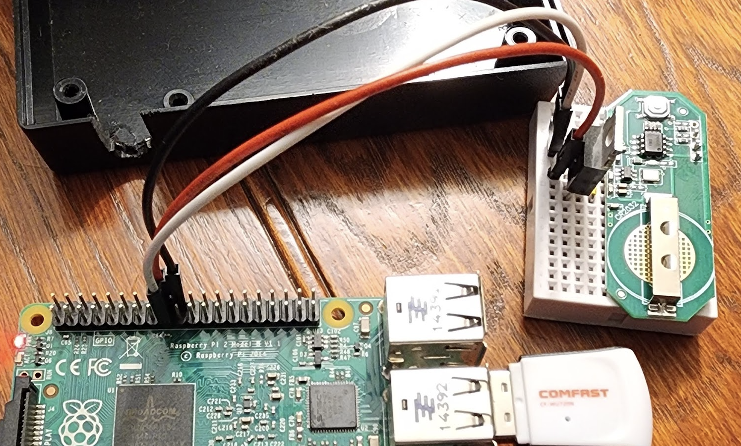
Finally, wire the breakout board you just constructed to the Raspberry Pi. Pin #17 serves a very convenient 3.3 volts, which is the perfect replacement for a CR2032 battery. There is a ground pin nearby on pin #20, as well as GPIO24 right between the two on pin #18. This makes for a nice clean patch between your breakout board and the Pi.
![]()
Internet-Enabled Garage Door Opener
Remotely open a garage door using an API call rather than a near-range 900MHz door remote
 DeckerEgo


Discussions
Become a Hackaday.io Member
Create an account to leave a comment. Already have an account? Log In.