 Arnov Sharma
-
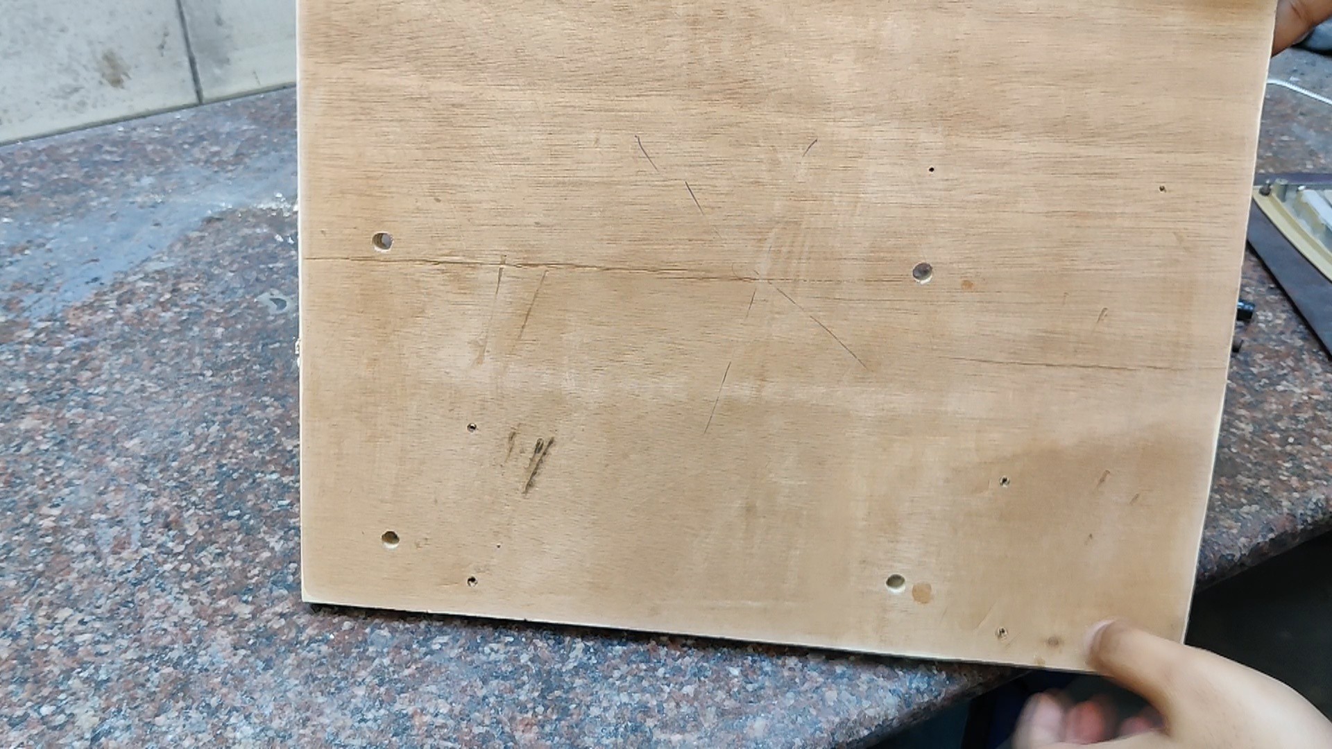
11Preparing the Wooden Base
As for the base, we use a 340x280mm plywood board.
![]()
![]()
![]()
![]()
![]()
![]()
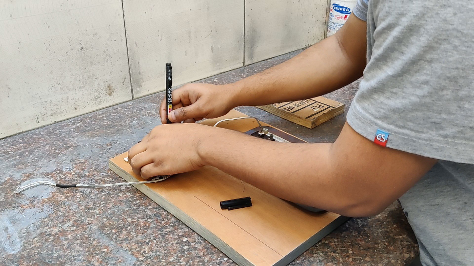
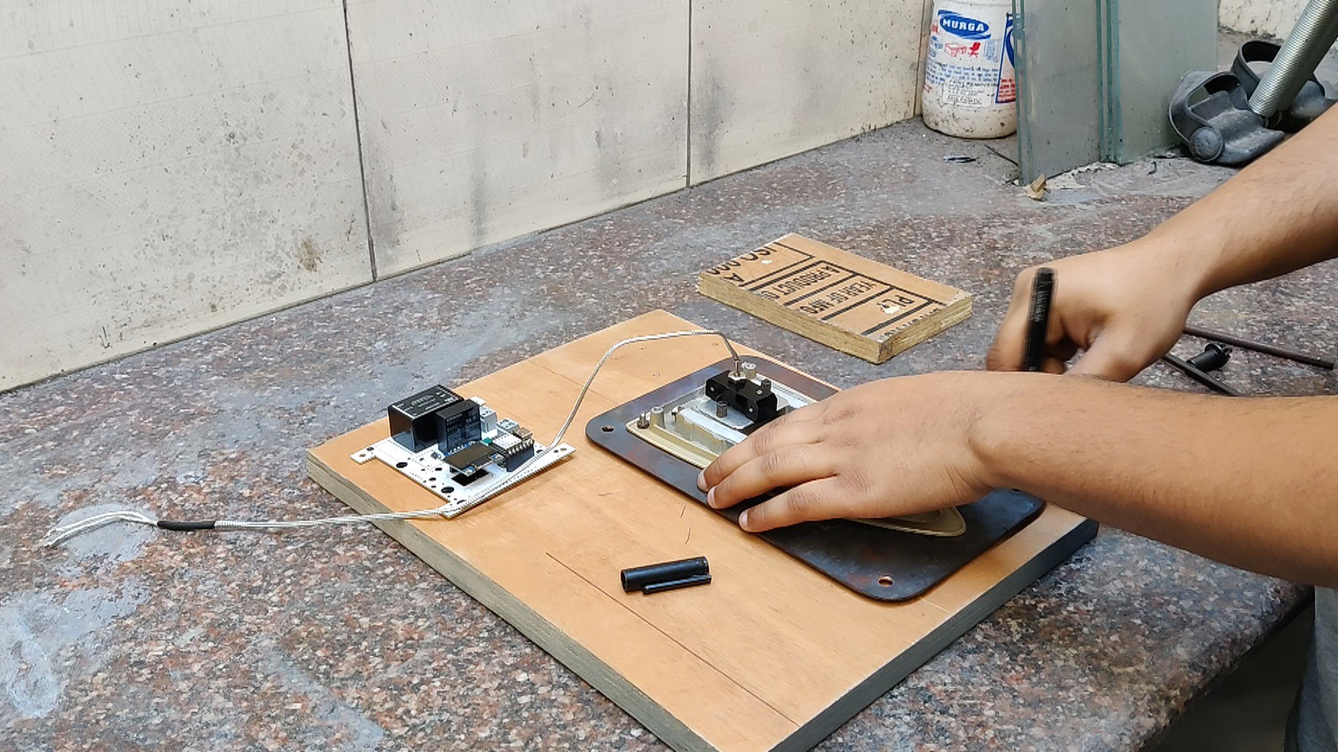
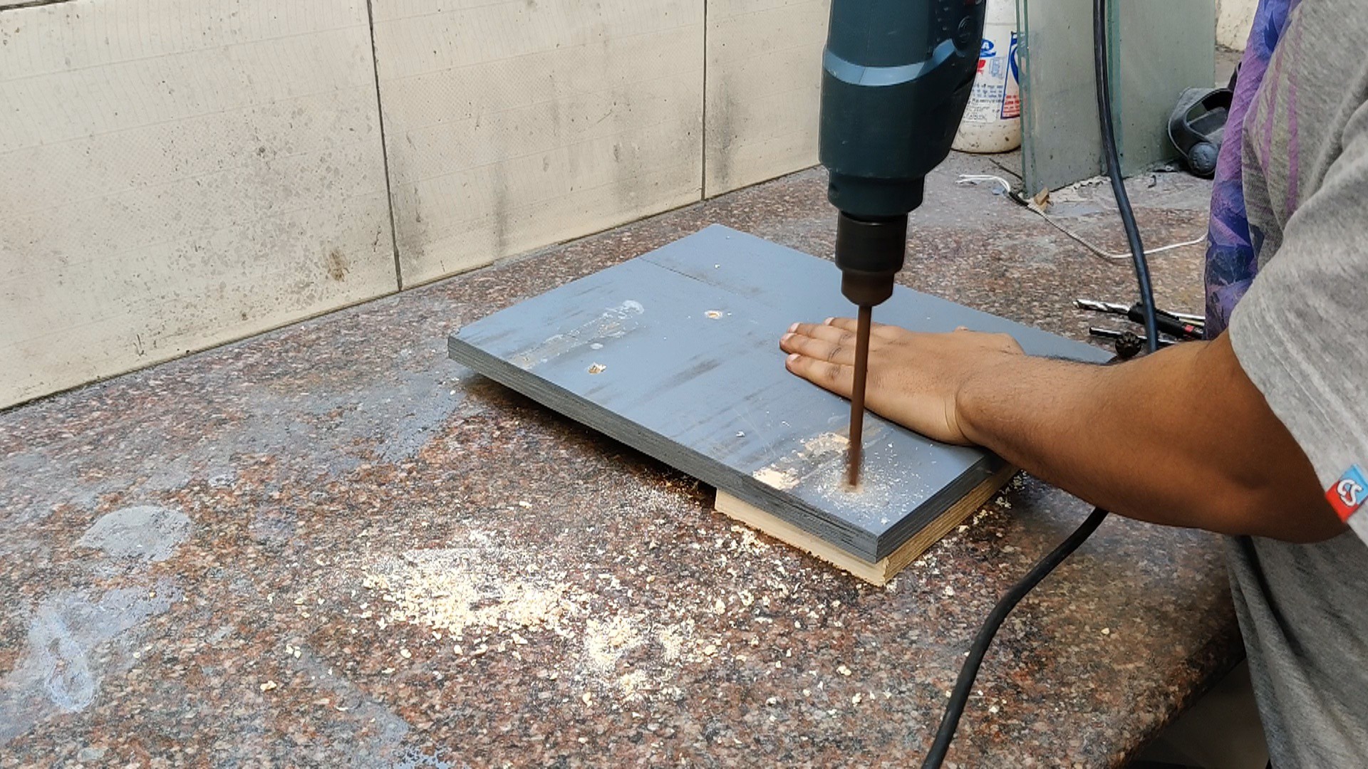
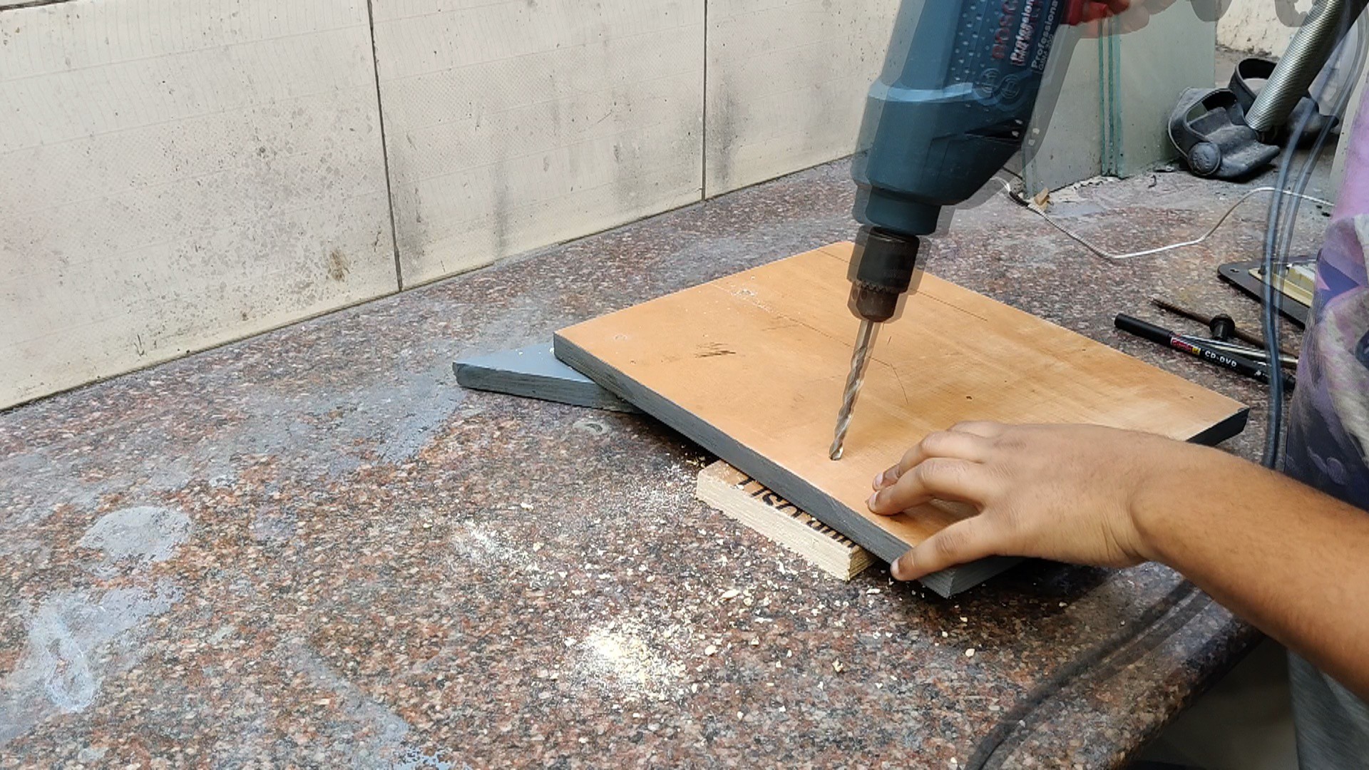
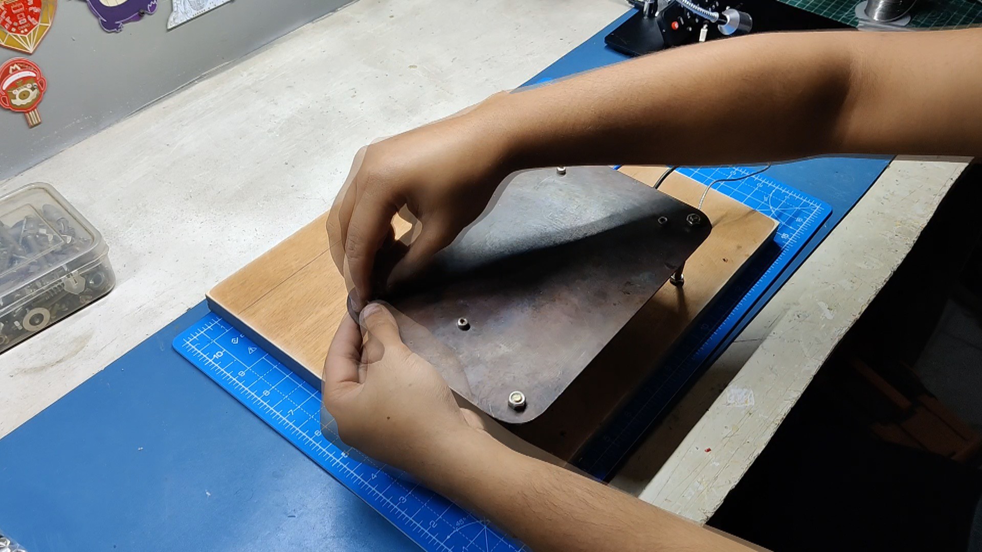
- Using a sharpie, we mark the location of the heating element plate's hole on the plywood after positioning it on one side.
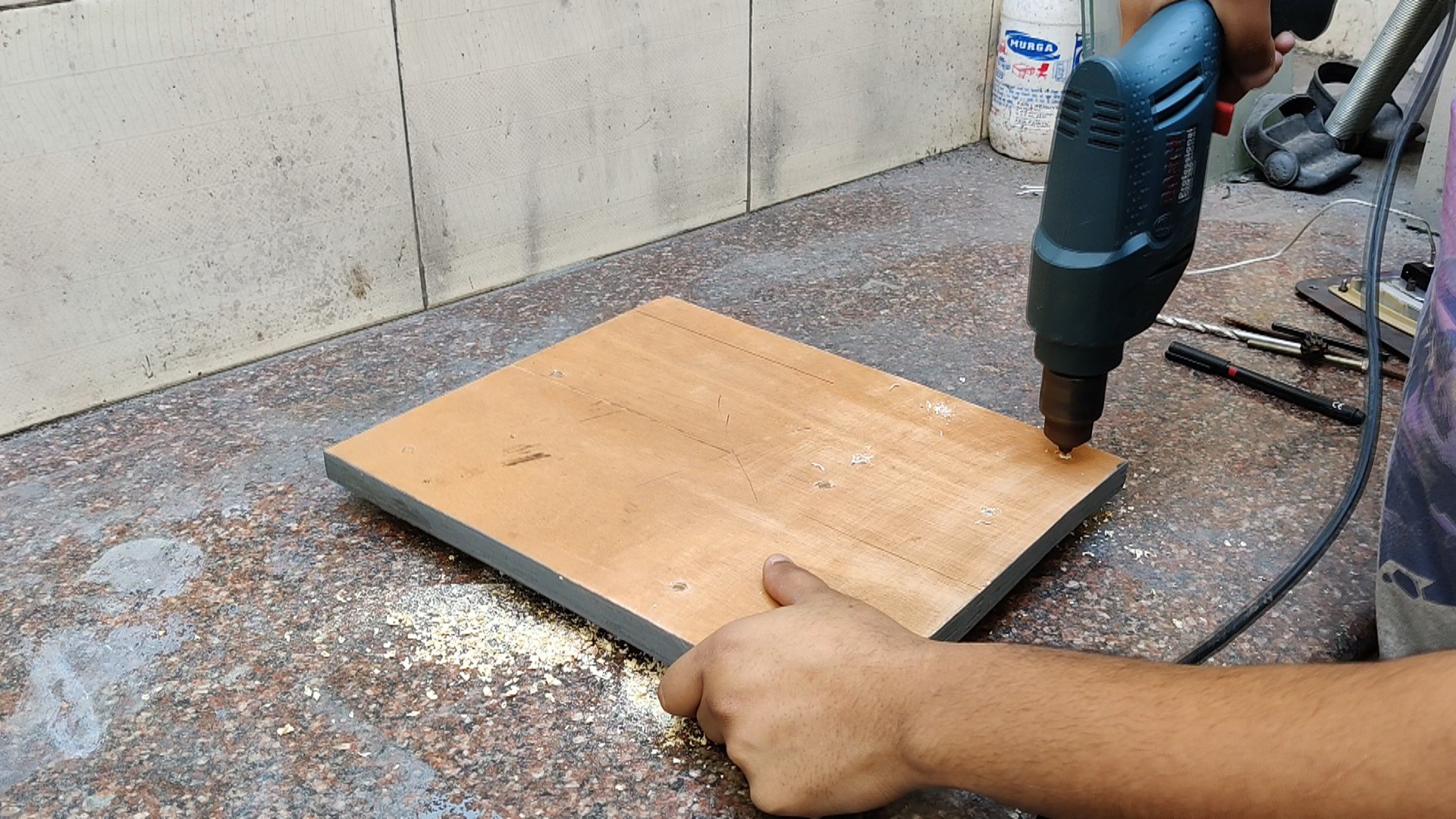
- We follow the same procedure for the circuit and then use a 6mm drill bit to drill holes for mounting the heating element plate.
- For circuits, we use a 2.5mm drill bit.
- Using a 10mm spade bit, we drill countersink holes in the 6mm hole on the bottom side of the wooden board. To install the heating element plate, we will be adding four M5 bolts from the back; the bolt head will go into the 10mm drilled hole.
-
12Wooden Base Assembly
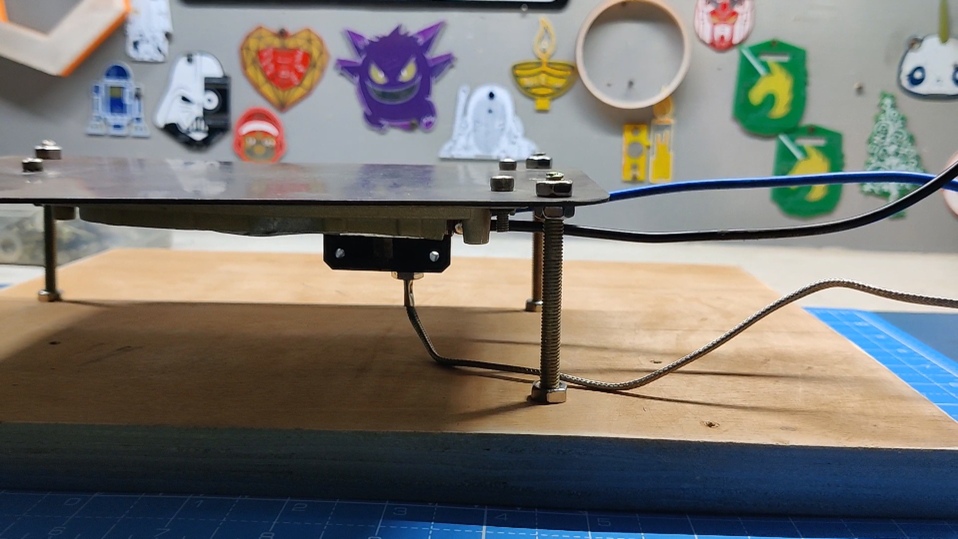
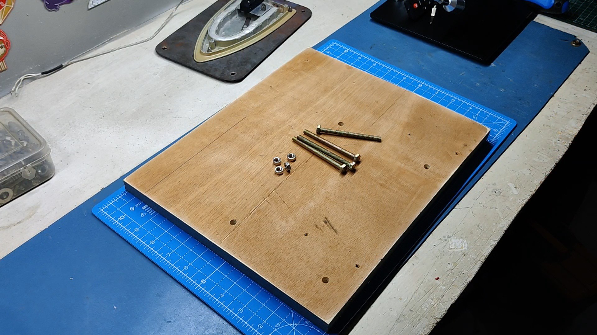
We use four M5 bolts and nuts to mount the heating element.
![]()
![]()
![]()
![]()
![]()
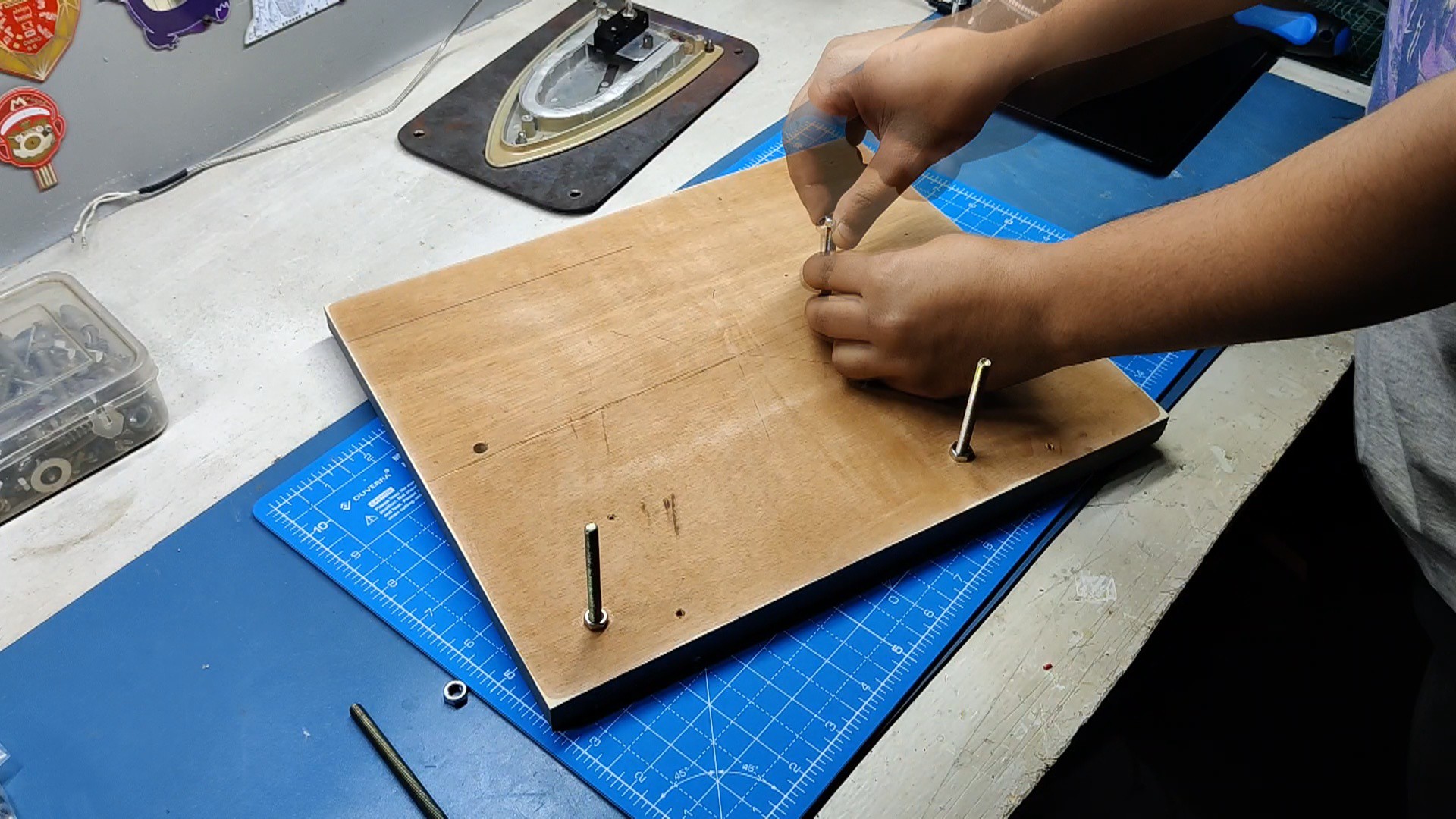
- To hold the four bolts in place, we first set them in the correct spots and tightened them with an M5 nut on each of them.
- Next, we place a nut on each bolt.
- The heating element plate was then installed on four M5 bolts; the nut that was placed earlier will keep the plate off the ground.
- We tighten the heating element plate in its position away from the wooden surface by adding four more M5 nuts, which will fully secure the assembly.
- Next, we use M3 screws to install the circuit onto the hardwood base. Four threaded inserts are used as spacers to maintain the circuit above ground.
-
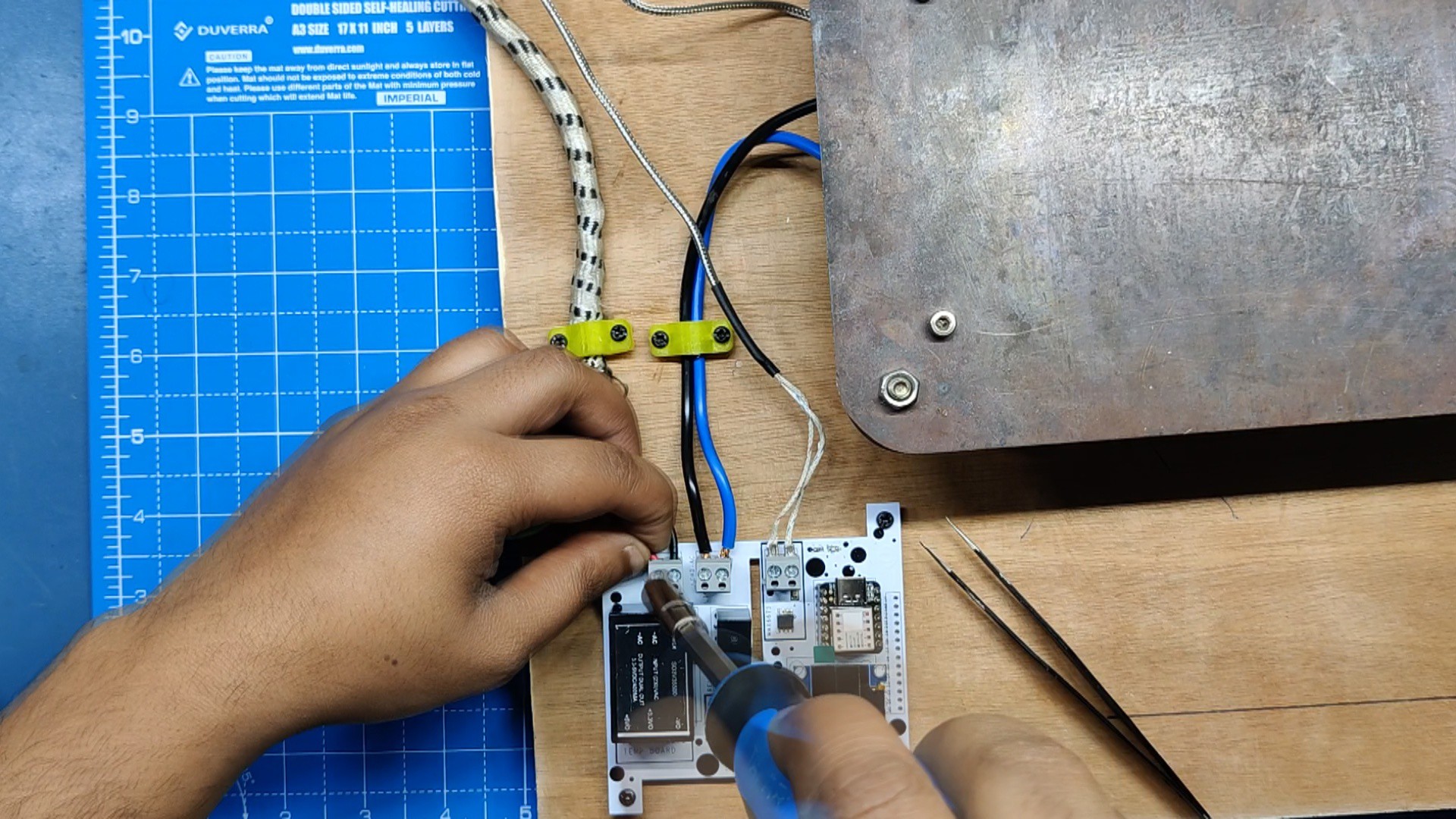
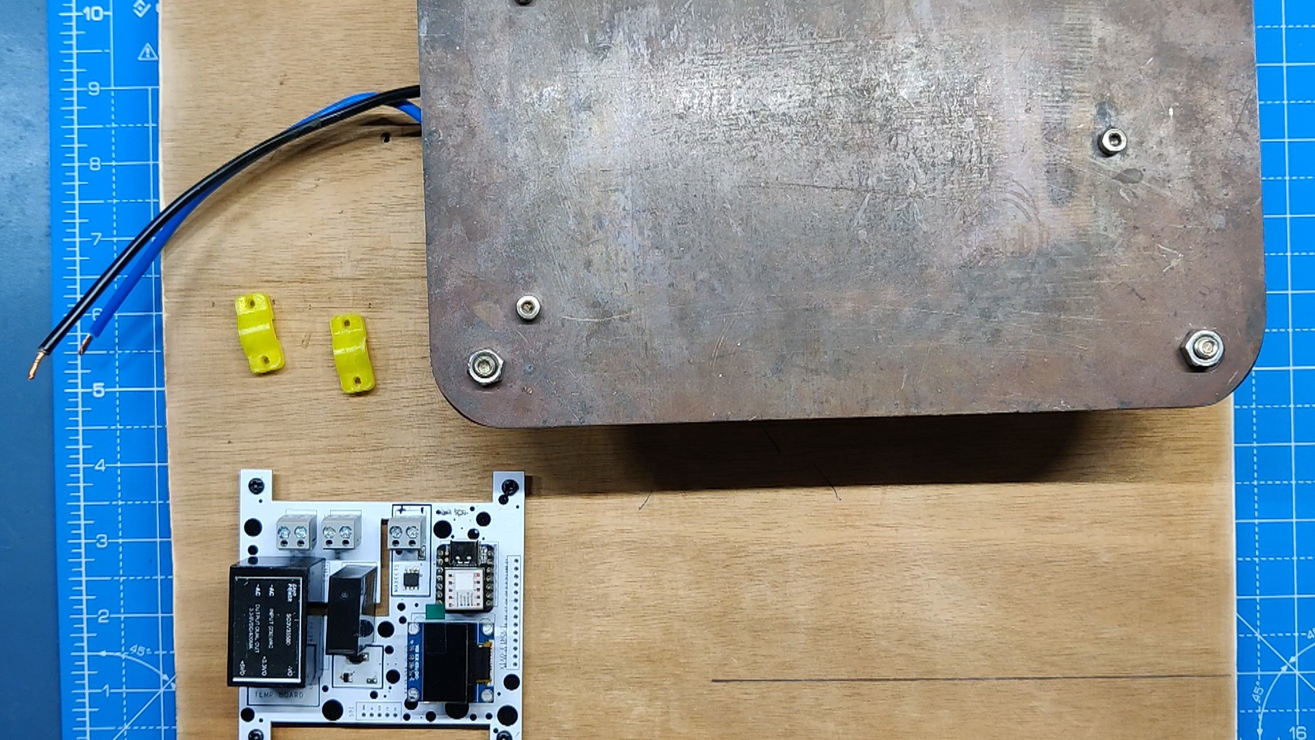
13WIRING
![]()
![]()
![]()
![]()
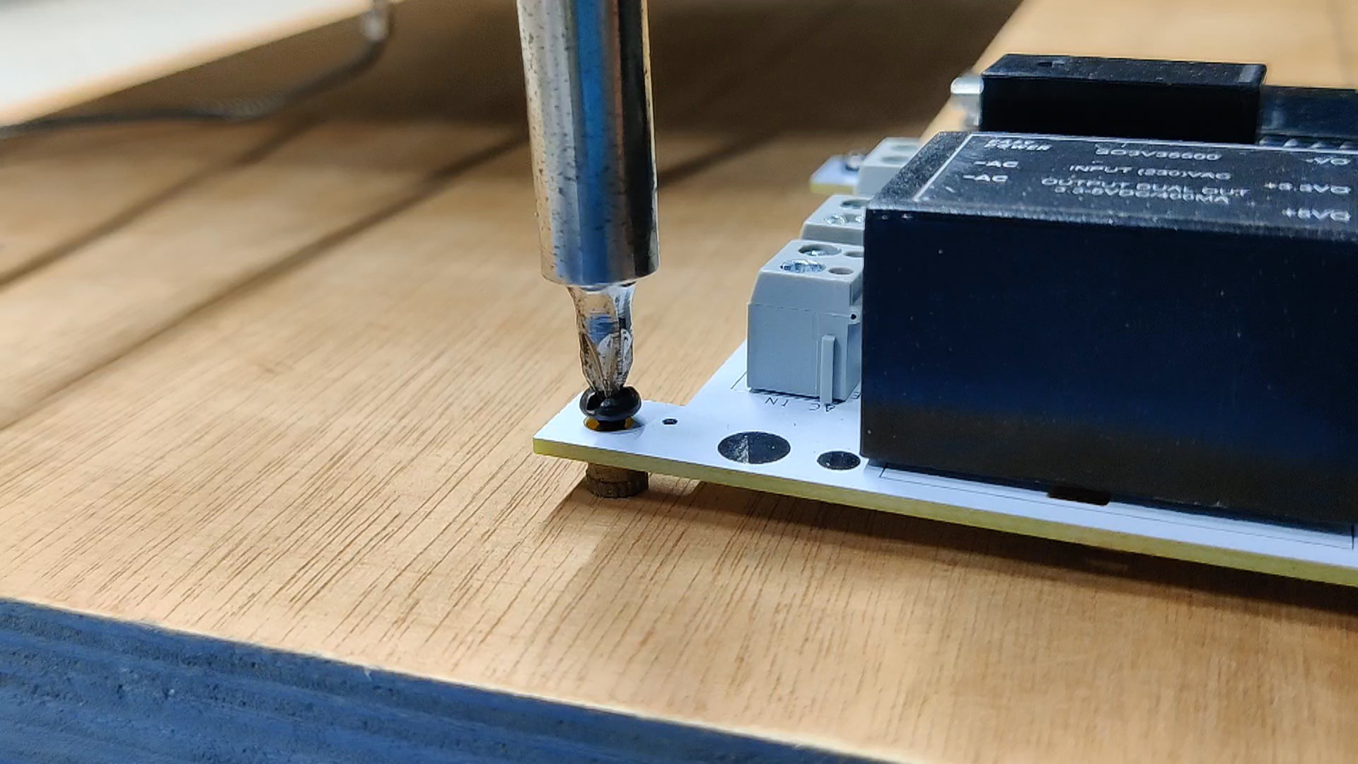
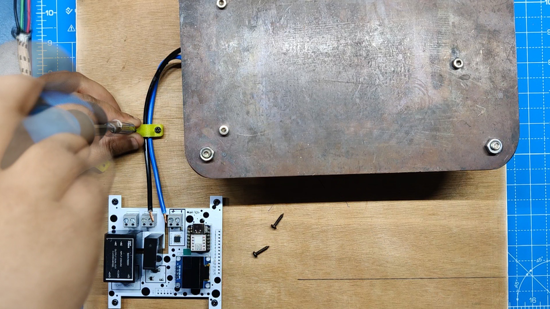
The wiring followed next, and it was really simple. We started by connecting the K-type thermistor terminals to the CON2 screw terminal port that was supplied on the circuit.
The AC Heating Element Terminals are next connected to the CON2 screw terminal, and finally, the live and neutral AC Power Cord connections are made to the CON2 screw terminal of the circuit.
Additionally, the hotplate surface is connected to the ground port of the AC power cord, preventing electrocution in the event of a short circuit.
Please note that working with AC is no joke. Remember, prioritizing safety is crucial when working with AC supply systems. Taking precautions helps create a secure working environment and reduces the risk of accidents or injuries.
After the wiring, the hotplate is now complete.
-
14Testing the Hotplate
For testing the hotplate, we have to prepare a SMD circuit for reflow.
![]()
![]()
![]()
![]()
![]()
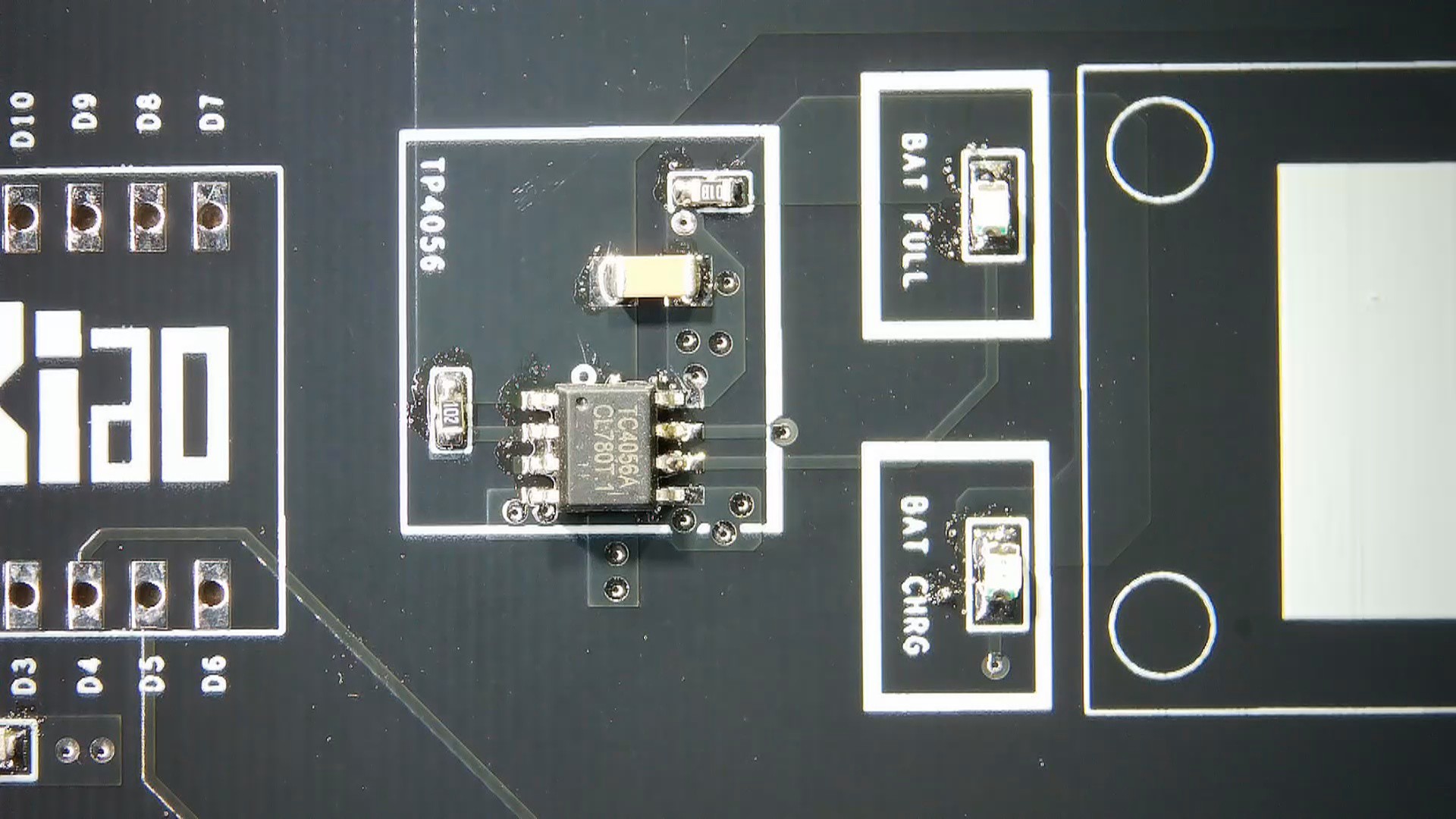
- After applying solder paste to each component pad, we arranged each SMD component in its designated spot one by one.
- Next, we place the circuit on the newly finished SMT reflow hotplate surface.
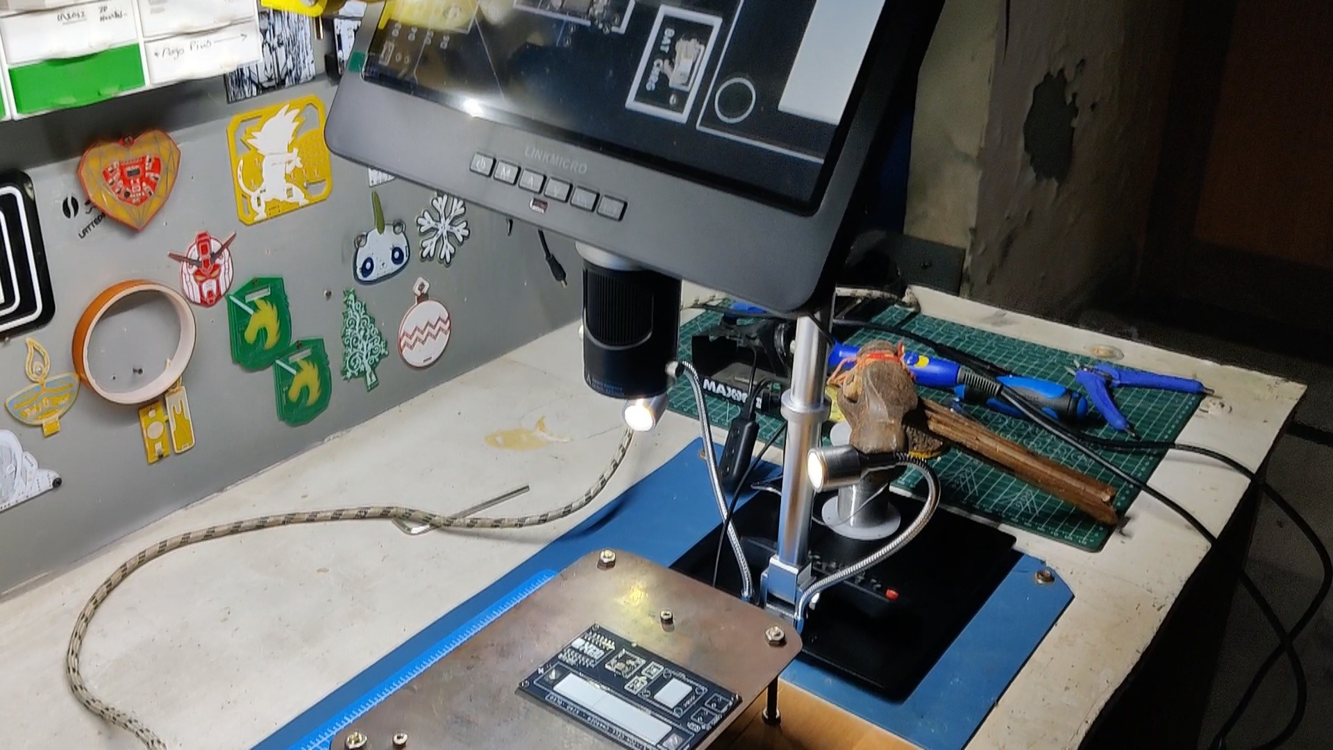
- We put up an overhead PCB microscope to watch the solder paste melting process in order to get a close-up look at the solder reflow process.
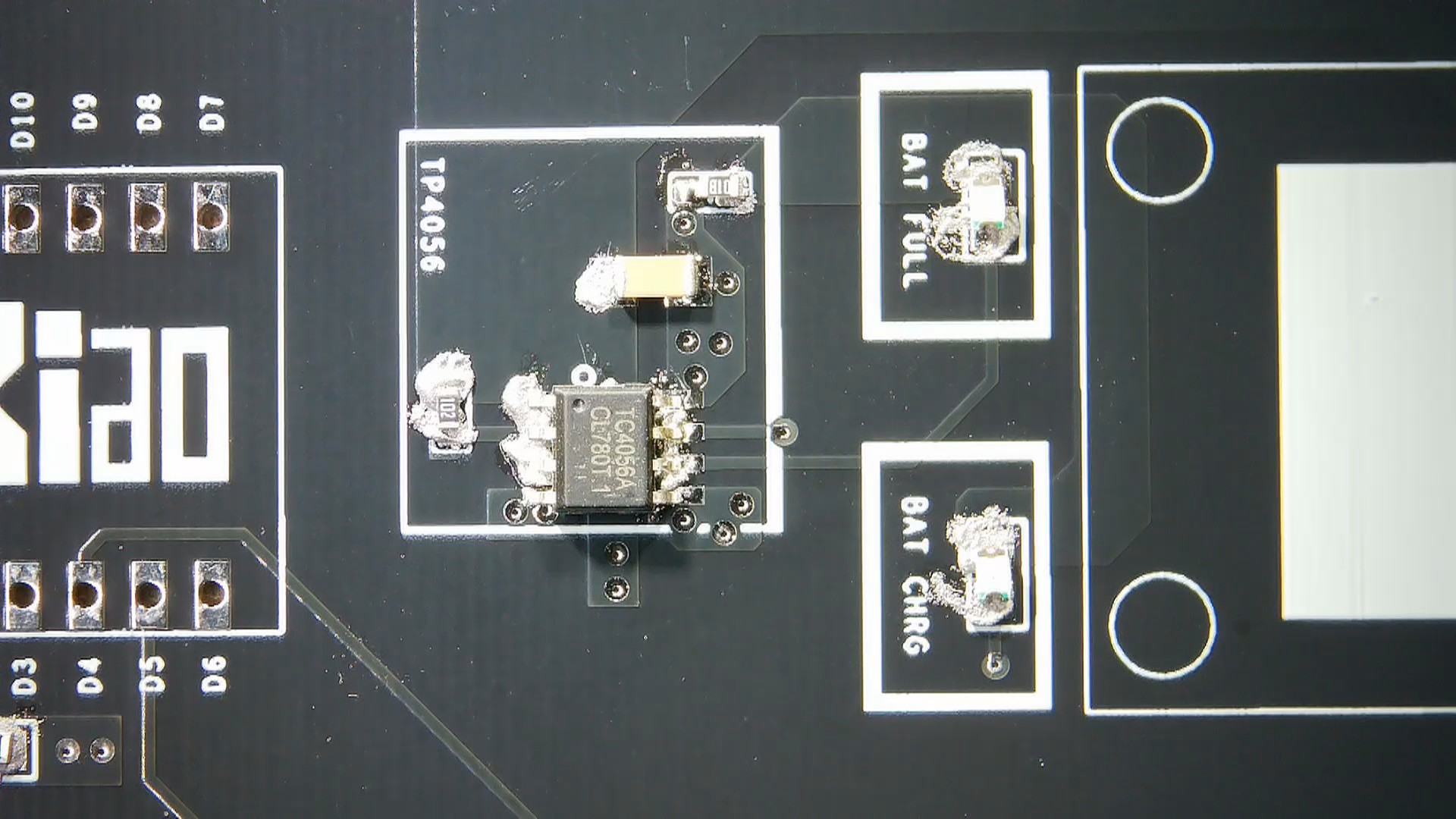
- Solder paste melts, and components are soldered onto their pads as soon as the hotplate reaches the melting temperature.
After operating for a while, the hotplate switches off when it reaches its threshold temperature. A relay then disconnects the power to the heating element, and the hotplate turns off again when the temperature falls below the threshold voltage. This process repeats in a loop.
By doing this, you may avoid the overheating and burst of the heating element that was a problem with the previous version. The reconnect feature in the new version also helps to eliminate this issue, so you can expect this hotplate to live much longer.
-
15Conclusion
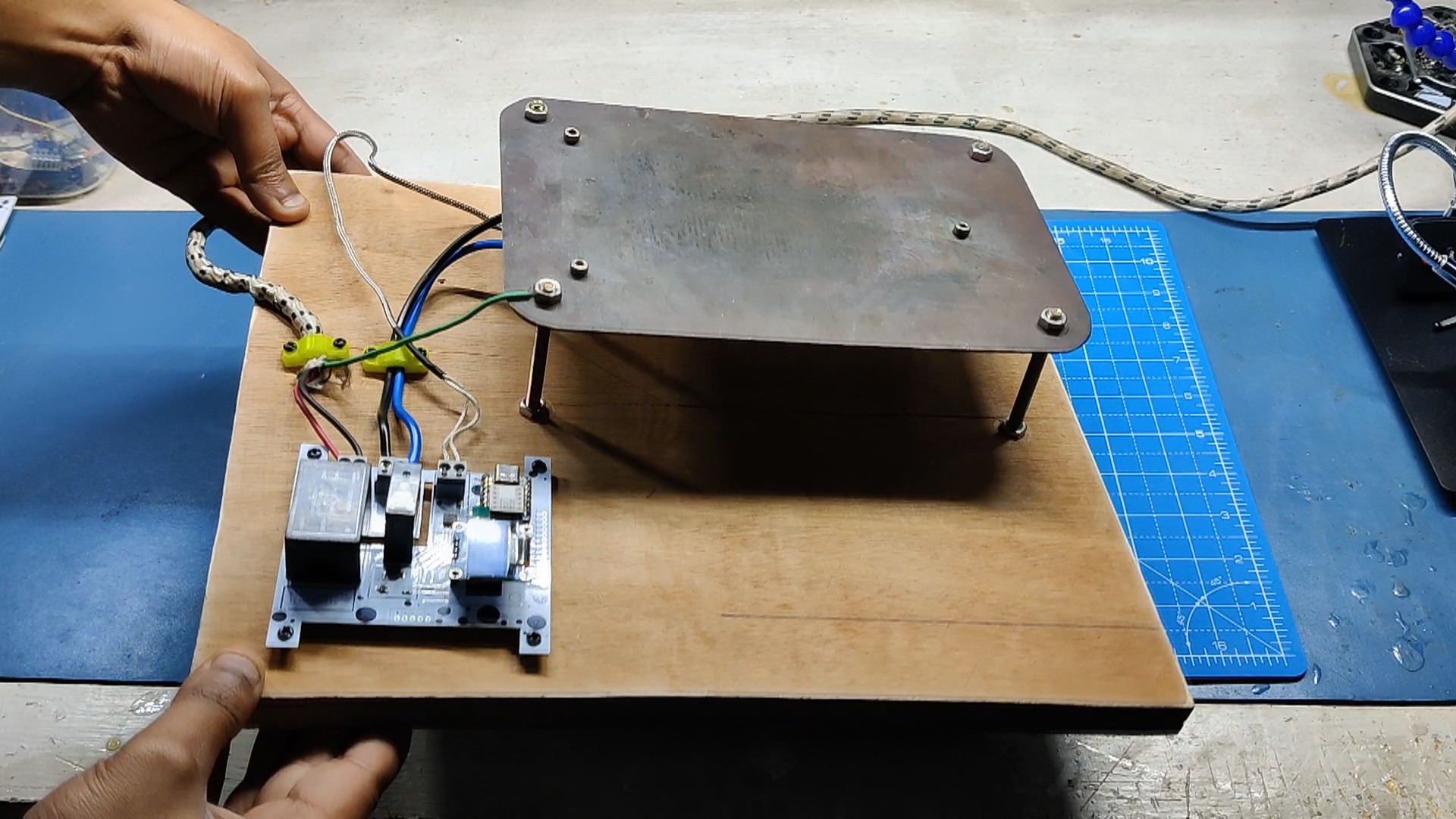
As verified in the previous step, the hotplate is functioning as expected.
![]()
![]()
The cutoff feature can be adjusted in the code because, after a few uses, it is evident that the temperature of the TOP surface and the temperature probe aluminum block differ; that is, if the aluminum block's temperature is 150, the actual temperature may be 200. This significant difference in readings can be fixed by positioning the thermometer probe as close to the top surface as possible.
It is therefore necessary for us to machine a new top surface that will be sufficiently thick to allow us to mount the element from below and attach the thermistor from one side.
Although there will soon be a new concept, the project is now functioning and will continue to do so for the next three to four years.
Leave a comment if you need any help regarding this project. This is it for today, folks.
Thanks to Seeed Studio for supporting this project.
You guys can check them out if you need great PCB and stencil service for less cost and great quality.
And I'll be back with a new project pretty soon!
Makeshift Reflow Hotplate
A clothes iron based PCB Reflow Hotplate with Temp Control, MAX6675 is being used with XIAO MCU.


Discussions
Become a Hackaday.io Member
Create an account to leave a comment. Already have an account? Log In.